Abstract Multistorey structures is one of the most used for the influence control of excessive drift, efficient and stiffness when subjected to lateral load is as the outrigger system. During the earthquake or wind load, the damage of non structural and structural form can be minimized. This paper studies “ANALYSIS OF OUTRIGGER SYSTEM FOR FRAME STRUCTURE SUBJECTED TO LATERAL LOAD” is the three dimensional model of 32 storey building have to bring into existence for analysis and design using ETABS software. To study the effect of outrigger system varying with different storey height of the building is perform as one, two, three and four outrigger level. This analysis of model is using method of Linear Static Method (Equivalent Static Method) and Linear Dynamic Method (Response Spectrum Method). The characteristics of efficiency and stiffness is to calculate the lateral displacement, base shear, story drift,andfundamental natural time period for different typesmodelwithandwithout outrigger system. So this case the reduction of displacement and drift is to minimized as compared to model of without outrigger system
1. INTRODUCTION
Analysis of Outrigger System for Frame Structure Subjected to Lateral Loads Syed Amir1, Syed Arfat2 1P.G. Student, Department of Civil Engineering K.B.N.U Kalaburagi, Karnataka, India 2Professor Department of Civil Engineering K.B.N.U Kalaburagi, Karnataka, India ***
International Research Journal of Engineering and Technology (IRJET) e-ISSN: 2395-0056 Volume: 08 Issue: 12 | Dec 2021 www.irjet.net p ISSN: 2395 0072 © 2021, IRJET | Impact Factor value: 7.529 | ISO 9001:2008 Certified Journal | Page367
Key Words: Frame Structure, Outrigger System, Seismic load,Lateraldisplacement,Storeydrift.
Tallbuildingdevelopmentisrapidlyincreasingaroundthe world, posing new challenges that must be met through engineering judgement. Lateral loads induced by wind or earthquakearefrequentlyresistedinmoderntallbuildings by a system of coupled shear walls. However, as the structureofbuildingrisesinheight,thestructure'sstiffnes becomesincreasinglysignificant,necessitatingtheadoption of a lateral load resisting system to give adequate lateral stiffnes. The dyanamic load resisting system effectively controls excess laterals load drift, lowering the risk of structural and non structural damage caused by small or medium lateral loads caused by wind or earthquake. This systemischosenasanappropriatestructureforhigh rise buildings, especially those in seismically active zones or wind load dominantareas From over course of the twentieth century, advances in concretetechnology,includingmaterials,structuralsystems, analyse,andconstructionsprocesses,madeitfeasiblecreate concretehighstructures.Theprimaryneedsofthebuilding aremetbystructuralsystems.Theinfluenceoflateralsload, suchaswind&earthquake,onthestructureofabuildings rises as it grows in height. Tall buildings are subjected to wind and seismic forces. become an essential design consideration. Tall structures' structural systems can be improvedtoregulatetheirdynamicresponse.
Buildingdeflectionisinfluencedbyearthquakesandwind loads.Aconcretecorehasbeeninstalledatthecentreofthe buildingtocounteractlateralloadscausedbyearthquakes and wind. Concrete core is an extremely efficient and practicalstructuralmethodfordecreasingbendingcaused by seismic and wind stresses. The hybrid frame concrete corewallstructurehasgrowninpopularityinrecentyears, with owners worried about its performance and cost Thesavings.allowable limit of top deflection in high buildings for wind study is 1/500 of the structure height, Part III of BureauofIndianStandards875:1987.Oneofmostessential requirements of selecting a structural system of a tall buildingislateraldriftatthetop.However,asabuilding's heightincreases,thecorewall'srigidityaloneisinsufficient towithstandwindandseismicforces.Thisissuenecessitates the development of new modern structural systems. Tall structuresarecreatedwithnumerousbracedtube,dia grid, andoutriggersystemsareexamplesofstructuralsystems, foreachcomplicatedformcategory.
Outriggersareaunitrigidhorizontalstructurei.e.trussor beamthatconnectcorewallandoutercolumnofbuildingto enhance building strength and overturning stiffness. Outriggers are employed in tall building for nearly from century,howeverinnovativestyleprinciplehasbeenupits potency.stabilizersystemisonestyleofstructuralsystem thatismade froma cantilever formed horizontal member connected to structures inner core and outer columns. Through the association, the instant arm of the core are goingtobeenlargedthatcausehigherlateralstiffnessofthe system. Central core during a building act as cantilever, outriggers area unit provided to scale back overturning momentincoreandtotransfermomentfromcoretoouter column by connecting the core and column. Wall frame stabilizertrussesisoneamongsttheforemosteconomical and economical structures in tall building, at outer finish theyconnectedtotheinspirationthroughexteriorcolumns
1.1 OUTRIGGER STRUCTURAL SYSTEM

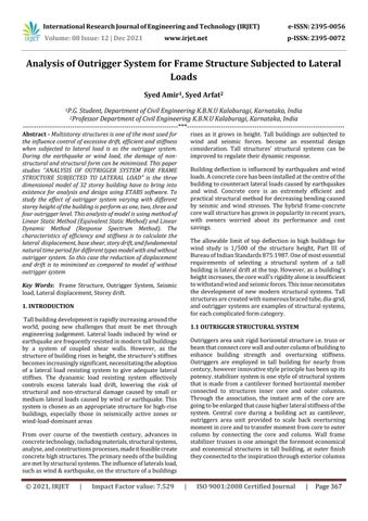
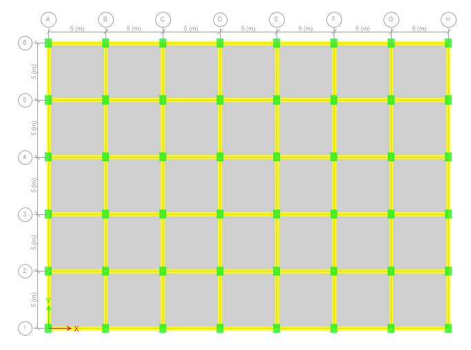
TheETABSsoftwaresystemisusedtoform3Dmodelandto hold out the analysis. The software system is ready to predict the behavior of house frames below static or dynamic loadings, taking under consideration material in snap.Thesoftwaresystemacceptsstaticmassessimilarlyas dynamicmassesandhastheflexibilitytoperformstaticand dynamicanalysis. The arrange layout of the RC SMRF building as shown in figurefive.1.Theelevationand3Dreadofvariousbuilding models also are shown on top of. during this study, the arrangeissameforallthemodels.everybuildingmodelisof thirty two constructions with storey height capable three.2m.thepeakofbottomconstructionisunbrokenasa pairof.5mforallthevariousbuildingmodels.Andseismal zoneVistakenintoaccountforthestudy.whereasscheming the seismal weight, precisely 0.5 (50%) of the ground loadingistakenintoaccount(IS1893 2002,clause7.3.1and 7.3.2).Theactknowledgegivenforallthevariousbuilding modelsisgivenbelow.
2. ANALYTICAL MODELLING
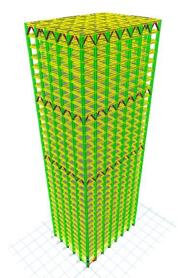
ModelDataStructure SMRF No.ofstories G+30 Storeyheight 3.2m IntensityofLiveLoad 3Kn/m2 Seismiczone 5th(0.36) Soiltype 2nd(medium) Importantfactors 1.5 Responsereductionfactors 5 Concretecolumn1 0.75x1.0m Concretecolumn2 0.6x0.8m Concretebeam 0.3x0.55m Gradeofconcrete M30 Gradeofsteel Fe500 SteelOutriggerbrace ISA200x200x12mmFe345 The outrigger system are analysis for the different model structuralformsasfollows FIG 1: PLANLAYOUT FIG 2: SectionalElevationand3DViewofBuilding withOutriggersandCoreWall
When the structure is subjected to horizontal loading, the wallandstabilizertrussescanrotate,inflictingcompression withinthedownwindcolumnandtensionincolumnonthe upwind aspect, these axial forces can resist the rotation within the wall. once the structure is subjected to lateral forces,stabilizerandcolumnsresisttherotationofthecore andthereforeconsiderablyscalebackthelateraldeflection and base moment, which might have arisen in a very free core. stabilizer structural systems not solely practiced in dominantthehighestdisplacementshoweveradditionally playsubstantialroleinreducingtheputdownleveldrifts
Theprimarygoalofseismicanalysisistomakethestructure earthquake resistant rather than earthquake proof. The structurespeciallydesignedforthispurposewillwithstand effects of shaking of ground, it donot fall during strong earthquakes.Inanothersense,theprimarygoalofseismic analysis is to assess forces that have evolved, their treatments,andtheabilityofstructuresandtheirelements to withstand these forces The seismic analysis methodologiesusedwereasfollows: I)LinearMethods a)Staticlinearanalysis(Equivalentstaticmethod) b) Analyses of linear dynamics (Response spectrum Theanalysis)Response Spectrum and Equivalent Static Method approachisusetostudy32 steelframeresistanttostorey momentsbuildinginthisstudy.Thebuilding'sperformance is measured in terms of lateral displacement, storey drift, baseshear,andtimeperiod,andoverturningmoment
International Research Journal of Engineering and Technology (IRJET) e-ISSN: 2395-0056 Volume: 08 Issue: 12 | Dec 2021 www.irjet.net p ISSN: 2395 0072 © 2021, IRJET | Impact Factor value: 7.529 | ISO 9001:2008 Certified Journal | Page368
1.2 METHODS OF SEISMIC ANALYSIS
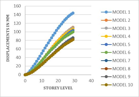
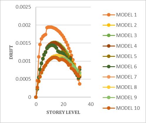
International Research Journal of Engineering and Technology (IRJET) e-ISSN: 2395-0056 Volume: 08 Issue: 12 | Dec 2021 www.irjet.net p ISSN: 2395 0072 © 2021, IRJET | Impact Factor value: 7.529 | ISO 9001:2008 Certified Journal | Page369 3. RESULTS AND DISCUSSIONS Inthistheresultsoftheselectedbuildingsarepresentedand discussed in detail. The results of base shear, lateral displacements,storeydrifts,andnaturalperiodofvibration andoverall performancefor thedifferent buildingmodels arepresentedandcompared. 3.1 LATERAL DISPLACEMENT This methods shown is for both the transverse & the longitudinaldirectionsofthatmodel.Accordingtothis,the displacement is maximum at highest top of the level structure and minimum at the base level. Thus the storey heightincreasewithlateraldisplacementalsoincreases.It observedthat,thedisplacementvaluesofmodeloutrigger systemarelessthanwithoutoutriggersystem FIG-3: LateralDisplacementforvariousModels Table 1: TopStoreyDisplacementforvariousModels 3.2 STOREY DRIFT Drift is mostly defined as comparative of lateral displacementoftwofloors.Drift isabsolutelyessentialfor controllimitdamagetointeriorsandexteriorspartsystems. According to INDIAN STANDARD 1893 (part 1) of 2002 considerthattheallowablestorydriftismeasuredas0.0004 timesofonestoryheightofstructure FIG-4: StoreyDriftforvariousModels TOP STOREY DISPLACEMENT (mm) MODEL EquivalentMethodStatic spectrumResponsemethod EQX EQY RSX RSY 1 148.821 162.333 112.797 112.797 2 116.951 128.632 80.544 84.192 3 114.95 127.071 79.028 83.032 4 112.103 124.704 77.683 82.033 5 109.851 122.847 75.984 80.754 6 104.729 118.07 72.993 77.907 7 92.159 97.14 62.858 63.884 8 91.399 96.576 62.818 63.885 9 91.933 96.941 63.515 64.35 10 87.366 93.741 63.016 64.894
MODEL
1 0.00194 0.00209 0.001655 0.00163 2 0.00152 0.00165 0.0011 0.00112 3 0.00151 0.00164 0.0011 0.00112 4 0.00151 0.00164 0.0011 0.00112 5 0.00144 0.00158 0.00107 0.00109 6 0.00144 0.00157 0.00107 0.00109 7 0.00115 0.00121 0.00081 0.00081 8 0.00115 0.00112 0.00081 0.00081 9 0.00108 0.00117 0.0008 0.0008 10 0.00105 0.00119 0.0082 0.00082
4.
MAX
3.3
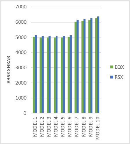
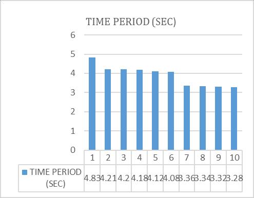
FIG 5: BaseShearforDifferentModelsbyEquivalent StaticandResponseSpectrumMethod TIME PERIOD
FIG 6: TimePeriodforDifferentModels CONCLUSIONS TheX bracedOutriggersareveryeffectivebecause theyhaveminimallateraldisplacement STOREY DRIFT Equivalent Static Method Response spectrum method EQX EQY RSX RSY
International Research Journal of Engineering and Technology (IRJET) e-ISSN: 2395-0056 Volume: 08 Issue: 12 | Dec 2021 www.irjet.net p ISSN: 2395 0072 © 2021, IRJET | Impact Factor value: 7.529 | ISO 9001:2008 Certified Journal | Page370 Table 2: MaxStoreyDriftforvariousmodels 3.3 BASE SHEAR Base shear can be defined as the maximum lateral force which will occur at base of structure because of seismic ground motion. Base shear is the deformation of base in which parallel planes of structure during an earthquake waves.Baseshearisanmaximumlateralforcesatthebase ofthebuildingwhensubjectedtoseismicloadorwindload.
All objects including buildings and the ground haveanaturalperiod,i.e.thetimeittakestoswingbackand forth,frompointAtopointBandbackagain.Seismicwaves whentravelsunderthegrounditalsomovesatitsnatural period.Itwillposeaproblemiftheperiodofbothgroundan buildingrestingongroundissame
International Research Journal of Engineering and Technology (IRJET) e-ISSN: 2395-0056 Volume: 08 Issue: 12 | Dec 2021 www.irjet.net p ISSN: 2395 0072 © 2021, IRJET | Impact Factor value: 7.529 | ISO 9001:2008 Certified Journal | Page371
International Journal of Engineering Research & Technology(IJERT),Vol.4Issue07,July 2015
The maximum lateral displacement in 32 story structures subjected to earthquake lateral load is reduced by 29.73 percent, and storey drift is reducedby25.77percent
[5] AbdulKarimMullah,SrinivasB.N,“AStudyonOutrigger System in a Tall R.C Structure with Steel Bracing”
When the outriggers system is used, the lateral deflectionordisplacementatthetoplevelismuch lowerwhentheoutriggerssystemsisnotused.
[2] AkshayKhanorkar,ShrutiSukhdeve,S.V.Denge&S.P. Raut,“OutriggerandBeltTrussSystemforTallBuilding toControlDeflection:AReview”GRDJournals Global Research and Development Journal for Engineering | Volume1|Issue6|May2016
Theoutriggerstructuresystemcansupportuptoa 50 storybuilding Wherethezoneisextremelysevere,thisoutrigger system or belt truss system of structures can be used.
REFERENCES
[1] Krunal Z. Mistry, Prof. Dhruti J. Dhyani, “Optimum outrigger location in outrigger structural system for high rise building” International Journal of Advance EngineeringandResearchDevelopmentVolume2,Issue 5,May 2015.
[3] B.S.Taranath, “Structural Analysis & Design of Tall Buildings”,NewYork,McGrawHill,1998.
[4] . Iyengar Hal, Composite and Steel High Rise Systems, Habitatand theHigh Rise, Tradition&Innovation.In Proceedings of the Fifth World Congress. 14 19 May 1995.Amsterdam,TheNetherlands,Bethlehem,Council onTallBuildingandUrbanHabitat,LehighUniversity