1.ManufacturingINTRODUCTION
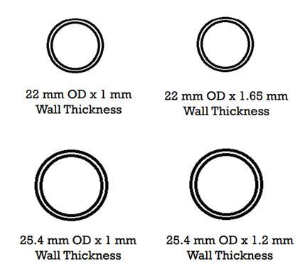
Table 1:MaterialPropertiesandspecifications Material 1018AISI 4130AISI steel2205Duplex steel2205Duplex diameterOutside cm2.540 cm2.540 cm2.540 cm2.540 thicknessWall 0.2cm 0.2cm 0.2cm 0.1cm stiffnessBending Nm2791 2 Nm2791 2 Nm2171 2 strengthBending Nm390 Nm382 Nm454 Nm260.4 Weight/meter kg/m1.6615 kg/m1.2444 kg/m1.1475 kg/m0.8790 Wehaveselected25.mmx1mmdimensionAISI4130pipe forourATV,aspertherequirementsofourvehicledesign, AISI 4130 is the most suitable material because of its lightweight nature, bending stiffness, and strength. We opted for steel which ensured better weight saving. Also, theavailabilityofAISI4130isgoodwithefficientcosting.
Key Words: Design, Analysis, Calculation, Material,
International Research Journal of Engineering and Technology (IRJET) e-ISSN: 2395-0056 Volume: 08 Issue: 12 | Dec 2021 www.irjet.net p ISSN: 2395 0072 © 2021, IRJET | Impact Factor value: 7.529 | ISO 9001:2008 Certified Journal | Page321
2.1 Selection of Material While designing a vehicle material selection is the key process in terms of safety, reliability, performance, strength, costing, and availability. On further research on several tube materials and compared them in multiple categoriesasfollows.
2. FRAME Rollcageisbasicallyachassiswiz.structuralfoundationof anATVwhichhousesallthecomponentsofthevehicle.Itis also responsible to keep the driver safe inside from any outer forces. Hence, we have to carefully develop the roll cageaccordingtotheproperprocedure.Firstly,selectionof material, then errorless designing in cad software and linear analysis and determining the force tolerance capability of roll cage. At the end check the ergonomics of the roll cage according to completion guidelines then, manufactureit.Manufacturingisalsoacrucialprocess,lots of failures can occur due to improper manufacturing techniquesandnegligence.
Design and Manufacturing of an ‘All Terrain Vehicle’
Rohan Gajbhiye1, Taru Sekhar Das2 1Captain, GHRCE Motorsports and Student Chairman, SAE India Collegiate Club GHRCE, Nagpur 2CAD/ CAE Engineer, Pune 1 Student, Dept. of Mechanical Engineering, G. H. Raisoni college of Engineering, Maharashtra, India 2 Student Alumni, Dept. of Mechanical Engineering, G. H. Raisoni college of Engineering, Maharashtra, India ***
Abstract GHRCE Motorsports team aims to build an ATV with maximum torque at wheels, maximum attainable velocity and gradeability but within the specified limitation stated by the SAE INDIA. The design part not only includes the modelling but the calculation at first hand which itself includes design of mechanical drives and elements. Ultimately achieving the practical parameters in synchronization with attained theoretical values is most important. The factor of safety should always be achieved within certain range. The vehicle handling, driver compatibility and maneuverability are major factors to be consideredforasuccessfulchampionship.
The development of ATV involves design process with simultaneous rectifications and analysis. It is after the validation of each and every component design and feasibility check that it is allowed for manufacturing. The vehicle consists of various dependent and independent parts whichneed to be separatelydesigned,analyzed and simulated along with each having its own dynamics and staticcalculations.Conceptualizationandvisualizationare majorcontributortoinitiationofdevelopmentofavehicle. Brief about this will be discussed in the paper with detaileddescriptionsandprototypepresentation.

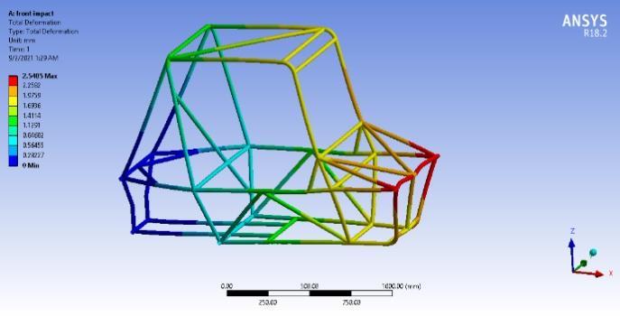
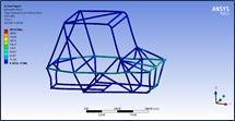
International Research Journal of Engineering and Technology (IRJET) e ISSN: 2395 0056 Volume: 08 Issue: 05 | May 2021 www.irjet.net p ISSN: 2395 0072 © 2021, IRJET | Impact Factor value: 7.529 | ISO 9001:2008 Certified Journal | Page322 *All the selections have been done according to design parametersand SPECIFICATIONScalculationsOFROLLCAGETable2Rollcagematerialspecifications Material: AISI4130 The thickness of the tube: 1.65mm Diameter of tube: 25.4mm Weight (approximate for roll cage): 30kg Total dimensions of roll cage: 1885 mm ×809 mm × 1135mm Weld joints: 51joints Weld length: 8000mm FOS: 2.07(average) Welding: For the fabrication of the final roll cage, we are going to use MIG welding and TIG welding because of effective and efficient welding. The reason behind the usage of MIG and TIG welding techniques are good weld quality, works with many metals and alloys, ease of use, longpasswelding,etc.Also,theweldabilityofAISI4130is goodenough. 2.2 FINITE ELEMENT ANALYSIS The following analysis were performed to check the feasibilityof design byFrontimpacttest,rearimpacttest, side impact test, rear wheel bump, heave, and twisting. The results are shown below in the table and figures paragraph Frontalimpactanalysis:Fig.2.1: Fig.2.2:DeformStress TEST: FRONT IMPACT TEST Forceapplied: 20,000N Stress: 281MPa Deformation: 2.5mm FOS: 1.63 Table2.1:Frontalimpactanalysis Sideimpactanalysis:Fig.2.3:Deform

Steeringsystem: Ackermann Steeringmechanism: Rackandpinion Ackermannpercentage% 110% Steeringratio 9:1 Caster 2deg. Camber 5deg. Kingpininclination 8deg. Steeringangle 36.18deg. Ackermannangle(deg.) 45°(inner),28.18°(outer) Turningradius 1422.4 mm (inner) 2743.3mm(outer)
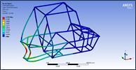
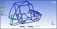
TEST: REAR IMPACT TEST Force: 20,000N Stress: 282MPa Deformation: 2.3mm FOS: 1.63 Table4.2:Sideimpactanalysis Rearimpactanalysis:Fig.2.5: Fig.2.6:DeformStress
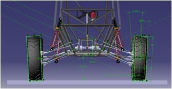
3.2 AckermannDesign:steeringmechanism: We are using Ackermann steering mechanism to increase the safety of vehicle while turning. The Ackermann steering mechanism is a geometrical arrangement of linkages in the steering of a vehicle designed to turn the inner and outer wheels at the appropriate angles. The tighter the desired vehicle turn radius, the larger the differenceinsteeranglesrequired.Steeringratioachieved is9:1meansforevery9 degreerotationofsteeringwheel rotates by 1 degree with rack and pinion mechanism. Ackermann percent value is more than 100 means the conditionofoversteerisachieved.Thecasterandcamber anglesinvehicleare2degreesand5degreesrespectively. All the setup helps vehicle to maintain proper grip with roadwhileturningandwhileclimbing whichincreasethe safety of vehicle. Maximum values for outer and inner angle for Ackermann steering is 45 degrees and 28.18 degrees respectively. Turning radius for inner wheel is 1422.4 mm and for outer wheel it is 2743.3 mm. below figuresindicatessteeringwheel assemblyandAckermann Specification:geometry.Table
3 SteeringsystemSpecifications PARAMETER VALUES
TEST: SIDEIMPACTTEST Force: 15,000N Stress: 243MPa Deformation: 1.59mm FOS: 1.89 Table2.3:Rearimpactanalysis
International Research Journal of Engineering and Technology (IRJET) e ISSN: 2395 0056 Volume: 08 Issue: 05 | May 2021 www.irjet.net p ISSN: 2395 0072 © 2021, IRJET | Impact Factor value: 7.529 | ISO 9001:2008 Certified Journal | Page323
Fig.2.4:Stress
3. STEERING 3.1 TheObjective:objective of steering system is to provide directional control of the vehicle, to withstand high stress in off terrainconditions,toreducesteeringeffortandtoprovide goodresponsefromroadtodriver.
4.2.2.RearSuspension: 4link H armsuspensionwaschoseninsteadof5inorder to replace the toe link and better capability to adjust to various parameters. Also, the loads are shared on the 4 mountings which will reduce the stress concentration. As like the front suspension, the rear upright is also a single manufactured piece which provides for the connection of theA armsandcallipers.
Table4.1 Specificationsofsuspensionsystem
4.1Objective: A BAJA suspension must be seamlessly engineered which will provide the ability to compete in every event with practical features like ground clearance and suspension travel which results in good comfort and control to the driveallowingpropernavigationinaroughterrain.
Doublewishbone: In automobiles, a double wishbone suspension is an independent suspension design using two wishbone shaped arms to locate the wheel. Each wishbone or arm hastwomountingpointstothechassisandonejointatthe knuckle.Theshock absorberand coilspringmount to the wishbonestocontrolverticalmovement.
Steeringwheelassembly Fig.3.2Ackermangeometry
SPECIFICATIONS FRONT REAR Type lowerdamperwishDoubleboneto Double wish bonedamperto upper springlength 200mm 378.2mm spring + damper length 393.7mm 546.248mm wirediameter 10mm 15mm meancoildia 80mm 120mm travelofspring 4inch 8inch springstiffness n/mm105.65 220.212n/mm
Fig.3.1
International Research Journal of Engineering and Technology (IRJET) e ISSN: 2395 0056 Volume: 08 Issue: 05 | May 2021 www.irjet.net p ISSN: 2395 0072 © 2021, IRJET | Impact Factor value: 7.529 | ISO 9001:2008 Certified Journal | Page324
4. SUSPENSION
4.2 TheDesign:designing process is done where the parameters like camber gain, motion ratio were analysed which are required for designing ATV suspension. The mounting points of the front and rear suspension were designed in SolidWorks. Then using these mounting points, the analysis was done in Lotus to verify the assumed parameters. Analysis of output is done in terms of graph between the parameters like wheel travel Vs. camber changeetc. 4.2.1.FrontSuspension: The front suspension is a short & long A arm wishbone arrangement. The roll centre is kept at the optimised height to reduce the body roll. The upright is manufacturedbyCNCandissymmetric,hasgoodstrength to absorb loads. The upright also provides a location to mountthebrakecalliper.Inordertocompensatefordive effects during aggressive cornering, the camber angle for the front suspension has been set at 0° at ride height. In additiontothat,thecamberanglehasbeensettodecrease whentheshockabsorbercompressesduringturns.
Shockabsorber: A shock absorber or damper is a mechanical or hydraulic device designed to absorb and damp shock impulses. It doesthisbyconvertingthekineticenergyoftheshockinto another form of energy which is then dissipated. Most shockabsorbersareaformofdashpot.
4.2.3.ShockAbsorbers: The rear shock absorbers were mounted on upper arm. The rear shock absorbers are stiffer than the front absorbers. Because of uneven distribution of weights, the stiffnessoftherearabsorbersiskepthigh.Therearshock absorbers were mounted on upper arm. The rear shock absorbersarestifferthanthefrontabsorbers.


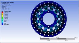
International Research Journal of Engineering and Technology (IRJET) e ISSN: 2395 0056 Volume: 08 Issue: 05 | May 2021 www.irjet.net p ISSN: 2395 0072 © 2021, IRJET | Impact Factor value: 7.529 | ISO 9001:2008 Certified Journal | Page325 pitch 25mm 37.8mm totalno.ofturns 9mm 11mm SPECIFICATIONS FRONT REAR Static scrub radius 50mm 0mm Percent anti dive/antisquat (antidive)29% (antisquat)57% Riderate N/m312.9 638.9N/m Roll center height from ground 305mm 303mm 4.2.4. SuspensionSpring:springs are the link between wheels and car body. Their primary task is to compensate uneven road surfaces and thus provide an assurance of high levels of ride comfort. Secondly, they must ensure that the wheels always have safe contact with the road regardless of its condition.SuspensionParameters Front Rear WheelRate 321.65N/m 676.48N/m SpringRate 105.65N/mm 105N/mm MotionRatio 0.41 0.41 Sprung Mass Naturalfrequency 1.2Hz 1.2Hz RideRate 312.9N/m 638.9N/m SpringStiffness 105.65N/mm 105.65N/mm Mean Coil Diameter 80mm 80mm OuterDiameter 90mm 90mm InnerDiameter 70mm 70mm Centreofgravity: WheelDiameter 22inches Weight of Front Wheel withRearelevated 130Kg RLF=Axle height above groundforFront 11inches=279.4mm RLR=Axle height above groundforRear 11inches=279.4mm H1=height of CG above 215.08mm wheelcentre CGheightaboveground 19.5inch Fig.3.1.Frontsuspensiongeometry TYRES: Tyres are designed to support the weight of the vehicle, absorb roadshocks,transmittraction,torqueandbraking forces to the road surface and maintain and change the directionoftravel.Tofulfilthesefourbasicfunctionstires are made of resilient rubber and filled with compressed Tyresair.ParameterSuspensionspecification: Front Rear TypeSuspension WishboneDouble WishboneDouble TyreSize 22inches 22inches 5.0 BRAKING 5.1TheObjective:purpose of the breaking system is to increase the safety and mobility of the vehicle by statically and dynamically all four tires on both paved and unpaved Specification:surface.Table5 Brakingsystemspecifications Specification Front&Rear Type Disc&hydraulic Brakeoftorque n359.93m 463.78n m Rotorsize 220mm M.Cdiameter 19.05mm
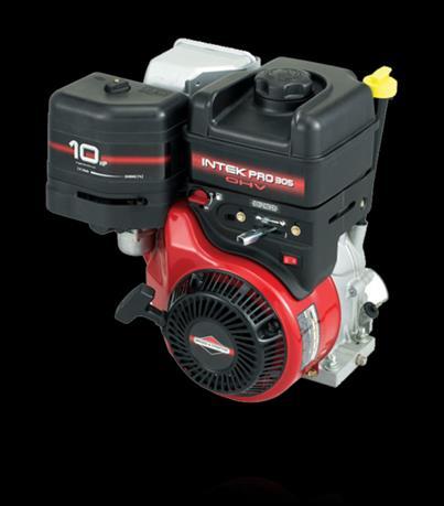
International Research Journal of Engineering and Technology (IRJET) e ISSN: 2395 0056 Volume: 08 Issue: 05 | May 2021 www.irjet.net p ISSN: 2395 0072 © 2021, IRJET | Impact Factor value: 7.529 | ISO 9001:2008 Certified Journal | Page326 Calliperpaddiameter 36mm Discthickness 4mm Pedalratio 6:1 Brakefluid DOT 4 Table5.1 Thermalpropertiesforbrakerotoranalysis. Heatflux Magnitude 23000w/m2 Convection coefficientFilm 230w/m2 temperatureAmbient 22°c Radiation Emissivity 1 temperatureAmbient 22°c Fig.4.1.Discanalysis Fig.4.2.InboardBrakingsystem 6.0 TRANSMISSION 6.1. TheObjective:mainobjectiveofthedrivetrainistovarythetorque in the most efficient way possible. This is being done throughpropergearreductionfortheneedsofthevehicle in the competition. We picked a manual transaxle over CVTbecauseofthefollowingreasons: •Widergearratiosrange •Givesbetteracceleration •Lighterandeconomical •Slippagelossesarelessinmanualgearbox •Heatgeneratedinmanualtransmissionislessduetothe timegapbetweentheshifts. 6.2. TheDesign:gearbox has been designed considering all the events oftheBaja competition,and soasto reduce the weight of the gearbox, ensure durability and outputs. And so to obtain the accurate gear ratio, and to meet all the requirements, reverse engineering method is adopted to designthe2 stagegearbox. 6.3Transmissioncalculation: Engine(aspertherulebookofBAJA2021): Engine=19L232 0054 G1(BriggsandStratton) Power=10HP=7.46kW EngineTorque(Te)=19.67Nm Speedinrpm(N)=3800rpm CVT=CVTShifter Ratio=0.9to3.9[150turningpossibilities] WheelDiameter:0.584m Radiusofwheel=0.292m WeightofVehicle:270 RollingResistanceCoefficient(µ):0.08 [Itismaximumconditionofallroads] EfficiencyofTransmission:75% [Assumedbyconsideringalllosses]

International Research Journal of Engineering and Technology (IRJET) e ISSN: 2395 0056 Volume: 08 Issue: 05 | May 2021 www.irjet.net p ISSN: 2395 0072 © 2021, IRJET | Impact Factor value: 7.529 | ISO 9001:2008 Certified Journal | Page327 Calculationsofgearratio: MaximumSpeedofvehicle=C.R*G.R*60N*C*E*3.6 N:Where,SpeedofEngine(inrpm) C:CircumferenceofVehicle(m) E: Torque=>57G.R.:C.R.:EfficiencyCVTRatioGearRatio=3800*3.14*0.584*0.75*3.60.9*G.R.*60G.R.=9.168(high)onWheel=Te*C.R.*G.R.*E(Considered)500=19.67*3.89*G.R.*0.75 G.R.=8.69(low) So,wetake9.168ratioforhightorque. STAGE1 STAGE2 No. of teeth PINION GEAR1 PINION GEAR2 16 48 16 54 Stage1G.R.=>48/16=3 Stage2G.R.=>54/16=3.375 Stage1G.R 3 Stage2G.R 3.375 GearRatio 9.168 BytakinglowerratioofCVT0.9andGearratioof9.168 Weget=> =8.250.9*9.168 N=3800/8.25 =460.6 ώ=2ΠN/60 =52.083 V=r*ω =0.292*52.083 =15.266m/s V=54.75 MaximumspeedofVehicle=54.75 TractiveEffort(T.E.)=Te*G.R*C.R*η/0.292 Acceleration=19.67*3.9*9.168*0.750.292T.E.=1806.43NR.R.=w*µ=270*9.81*0.08R.R=211.896N=F net/m=T.E R.R/m =1594.54/270 =5.9m/s2 Gradeability=100*(T.E. R.R.Coefficient)/W =100*(1806.43 0.08)/270*9.81 =60.20% Torqueonwheel=19.67*3.9*9.168*0.75 =527.47Nm MaximumSpeedofVehicle=54.75km/hr TractiveEffort[T.E.]=1809.43N RollingResistance=211.896N Acceleration=5.9m/s2 Gradeability=60.20% Torqueonwheel=527.47Nm GearRatio=9.168[thisissuitableforhightorque] Table6.1 SpecificationofTransmissionsystem Specifications Front&rear Maximumspeedofvehicles 54.75km/hr Tractiveeffort 1806.43N
[2] Milliken,DouglasL.,and WilliamF.Milliken. RaceCar Vehicle Dynamics: Problems, Answers, and Experiments. Warrendale, PA: SAE International, 2003. [3] SAEINDIABAJA2021Rulebook [4] Taghavifar,Hamid&Mardani,Aref&HajiHosseinloo, Ashkan. (2016). Off road vehicle dynamics: Stability, ride comfort, vehicle performance and modeling Advances 97.MechanicalEngineering.8.10.1177/16878140166618in
TheelectricalcomponentsinourATVareinstalledforour safetymajors.Weareinstallingtwokillswitcheswitheasy accessibility, to isolate the current from engine easily. By using SAEBAJA standards we are installing brake lights, reverse light and reverse alarm which will activate in emergency situation. To co ordinates the drive we are mounting GPS system in cockpit area displays the directionsandspeedofvehicles. We are using X2Mx type transponder in STV to for laps completing b to a timing device on the track. All the components we are mounted are safely securely by 9v batteries.WiringisdonebyabidingrulebookofSAEBAJA.
REFERENCES [1] Gillespie, Thomas D.Fundamentals of Vehicle Dynamics.SAEInternational,1992.
Thedesignandanalysisofeverycomponentisverycrucial for development of a safe and reliable vehicle. All the important aspects contribute to the overall performance andbuildqualityofthevehicle.
BIOGRAPHIES
ACKNOWLEDGEMENT We would like to thank our teachers and faculty advisers for providing with best of advices and knowledge to supportourwork.
“Rohan Gajbhiye is a highly knowledgeable and skilled student who has decent experience in motorsports. He is immensely passionateaboutautomobiles.“ “Taru Sekhar Das is an Alumni of the respective university. Lead the design teaminallmotorsport’sevents.Highly skilled in mechanical and automobile design, currently working as a CAD engineerinareputedMNC.“
CONCLUSIONS
International Research Journal of Engineering and Technology (IRJET) e ISSN: 2395 0056 Volume: 08 Issue: 05 | May 2021 www.irjet.net p ISSN: 2395 0072 © 2021, IRJET | Impact Factor value: 7.529 | ISO 9001:2008 Certified Journal | Page328 Rollingresistance 211.896N Acceleration 5.9m/s2 Gradeability(in%) 60.20% Gradeangle 31.047º Torqueonwheel 527.47Nm. Fig.5.1.BajaATVengine 7.0 ELECTRIC SYSTEM