Abstract: In this thesis, “THE BEHAVIOR OF R.C.C HIGH RISE BUILDING UNDER EARTHQUAKE LOAD BY ADOPTING LINEAR DYNAMIC ANALYSIS” is being done and the behaviour of building with and without infilled wall under seismic loadactionsisexplored.Infillbehaveslikecompressionstrutbetweencolumnandbeamandcompressionforcestransfers from one node to another. As the infill act as a compression strut member between column and beam and transfers compression forces from one node to another. The influence of masonry infill wall on the high rise building is studied under Dynamicanalysisi.e.,responsespectrumanalysisonhighrisebuildingwithandwithoutinfillwallsisperformfor theanalysisG+25 StoryRCC framedis modelled andanalysedEarthquakelateralloadingisappliedtothemodels.Many cases of analysis in zone II is taken. Base shear, storey displacement and storey drift for the both the case of infill and without fill wallsareanalysed bysoftwareETABSandcomparewiththe models.After observingthe valuesobtainedfor the models, it is shows that the decrease of displacements drifts and time period and increase base shear. Hence, it is necessarytoobservetheeffectofmasonryinfillwallfortheseismiccalculationofRCCframe
International Research Journal of Engineering and Technology (IRJET) e ISSN: 2395 0056 Volume: 08 Issue: 12 | Dec 2021 www.irjet.net p ISSN: 2395 0072 © 2021, IRJET | Impact Factor value: 7.529 | ISO 9001:2008 Certified Journal | Page261 THE BEHAVIOR OF R.C.C HIGH-RISE BUILDING UNDER EARTHQUAKE LOAD BY ADOPTING LINEAR DYNAMIC ANALYSIS PONNAPOLA SASIKUMAR1 , V.SIVA NAGENDRA BABU2
Thoughtheinfillisanon structuralmember,asitisseen in the past damages due to the seismic action or earthquakes leads to the concern of infill wall frames withtheongoingbareframemethod.
As the population is increasing day by day, it is the requirement of the people to build the structure in verticallyaslong aspossiblesuchas High Rise Building. InmosturbanizedareasoftheIndia,theirmuchneedof accommodation,soitisneedtohaveHighRiseBuilding. InmanydevelopingcountriesandIndiathedevelopment of moment resisting with infilled brick masonry walls are commonly constructed. Around the world, the basic construction material is the masonry, due to its availability, its usage and their cost. The basic use of masonry structure or reinforced concrete is to protect the structures from the environment effect or to partitionofspacesinsidethebuilding. While constructing any building structures, engineers usually neglect the importance of infill walls and it is treated as non structural elements or members. As it is difficulttoanalysistheinteractionofinfillwallswiththe structural frames and it creates problem for analgising the structure in the addition of infill walls. So it is removed in the analysis of building structures. As the lateral loading system of the building structure will be more if masonry infills walls are connected with the other structural frames such as beams, columns and slabs. The use of such consideration creates an inappropriate or incorrect behaviour of the structures when the structure is loaded for the lateral loading Thesystems.researchers are establishing the importance of moment resisting frames and their function in the transfer of load to the structures. As the incident of building collapseunderseismicor lateral loadingshows the importance of this aspects of masonry infills. The usage of infilled walls creates more stiffness and strength to the structure under the action of lateral loadings. It is not appropriate or incorrect to say the results of the design procedure without considering the effect of masonry infill or infill walls as lateral loading.
1M. Tech Scholar1 , Department of Civil Engineering, ST. Mary’s Group of Institutions Guntur, Andhra Pradesh, India
Keyword’s: Hise rise Building, Dynamic, displacement 1. INTRODUCTION
2Asst Professor2, Department of Civil Engineering, ST. Mary’s Group of Institutions Guntur, Andhra Pradesh, India ***
Theaimofthisworkistostudyorfindthestrengthand stiffness of the building with and without infill walls under lateral loading conditions. A 3 D model is created by using computer programming software such as ETABS,acomparisonstudyshouldbemadebetweenthe structures with infill and without infill walls. Their tensile capacities, which were negligible, were disregarded. In order to compare and understand the effect of masonry infill walls, analyses were also carried outforbareframes,i.e.withoutanyinfillwall.
1.1 Objective Objective of this project is to demonstrate or study the response of masonry infill panels on the earthquake effectofRCCHighRiseBuildingbyconsideringthelinear dynamic method i.e. equivalent or spectrum analysis. The observation obtained by comparison of G+20 High Rise Building for infilled frame and without infilled frames. The observation should be study in terms of i) JointDisplacementii)Storeydriftiii)Baseshear.

International Research Journal of Engineering and Technology (IRJET) e ISSN: 2395 0056 Volume: 08 Issue: 12 | Dec 2021 www.irjet.net p ISSN: 2395 0072 © 2021, IRJET | Impact Factor value: 7.529 | ISO 9001:2008 Certified Journal | Page262
ARCinfilledframeisthemostconcernstructuralframes for many budding researchers. However, most of these studies have been carried out in order to increase the lateral load capacity of pre 70s buildings. In the early and on pre 70’s buildings the main cause to reduce the damage of structural frame is the use of infill walls as lateral support to the structures and increases the strengthofthestructuresto some extents. Onlysome of theresearchersconcernorfocussedonthepreventionof damagetoinfillwalls.
Therefore, considering the effects of infill walls in the structural behaviour, several state of the art technological solutions and design methods have been investigated in order to both However to reduce the effect of infill walls in the frames structure response many developing innovation technologies to develop variousmethodstobeinvestigated,soasto 1.3 USAGE OF MASONRY INFILLS
Many under developed or developing countries is normally using the masonry infill walls which may be unreinforced clay bricks or hollow masonry blocks is available around the world at a very cheaper cost becauseoftheavailabilityofthematerialswithlowcost labour availability make this material the preferred choice.
In many parts of the world, the people are worried about increasing labour expenditure, non availabilityoftrainedlabourandmoretime consuming construction method they preferred precastbrickwork.
Solid walls are mostly constructed around the world because of their culture. Outer walls are constructedwithsolidwalls.
Inrecentstudies,theresearcherhasfoundtheeconomic loss due to the failure of a non structural component suchasinfillwalls,increasesthecostofstructuresdueto non innovation of new techniques to overcome losses. However it is necessary to innovate research work to reducethedamageofthestructureswithinfillwalls The scientific or concept wise ideas to be implemented to tackle the behaviour of infill walls due to lateral load or seismic actions. Moreover the loss due to infill walls at normal seismic influence will be reduced/eliminate and thelossofenergywithseismicactioncanbereducingby Aothermeans.graphrepresentsthebaseshearversesthelateraldrift forinfilledandbareframeshowninfigure1.1
As by using limiting design method the reductionofthedamageofthestructurescanbe minimizedforthestructuralresponse.
The cavities on the masonry brick skins can be effectively use as protection under weather condition, if it is properly constructed. The face brick outer skin of cavity walls provides a hardwearing maintenance free façade finish provided proper articulation is adopted and cracking of brick walls is avoided. The construction of cavity brick is costly and expensive for many under develop and poor countries. As the single masonry brick is constructed with the mixture of ordinary cement/ gypsum content and water retarding paintsontheinfillmasonrywall.
1.2 Infill Walls
Toreducethedamageeffectofinfillwallsand
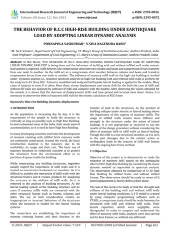
Figure 2.Frames with infills.
Infilled panelsarethewall betweenthe beams,columns or between floors which can be position and construction are subjected to induce applied loadings. Increaseinthehorizontalstrength,stiffnessandseismic energy loss by the use of infill walls with RCC frame structuresitisknownmostly. Whenever any lateral load acts on the building structures, the infill walls are the most effected element anditsbehavioureffectslateraldeflectionduetoseismic action. The basic four types of failures generally occurs intheinfill wallsarebreaking atcentreandcornerends ofwalls,shearfailanddiagonalstrutdamage.
Figure 1. The above graph shows the base shear vs lateral drift curves

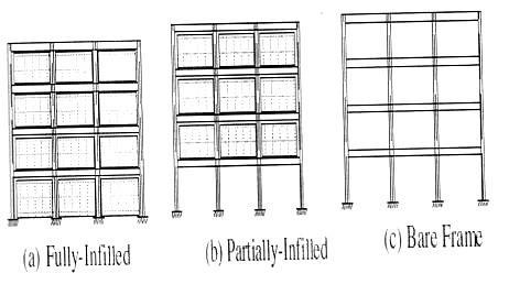
Figure 3. Movement of seismic or earthquake waves from the origin to the earth surfaces
Figure 2.4 Influence of seismic propagation under the surface of the building
Figure 4. Indian seismic zone map as per I.S: 1893(PART 1) 2002
Typical considered to be those which act parallel to the ground plane may occur at many angles other than perfectlyhorizontalgenerallyutilizedastheverticalload tothenormalbuildingsystems
International Research Journal of Engineering and Technology (IRJET) e ISSN: 2395 0056 Volume: 08 Issue: 12 | Dec 2021 www.irjet.net p ISSN: 2395 0072 © 2021, IRJET | Impact Factor value: 7.529 | ISO 9001:2008 Certified Journal | Page263 TYPES OF INFILL WALLING Masonryinfillwalls Concreteinfillwalls Timberframedinfillwalls Lightsteelframedinfillwalls Stonewalls 2. LATERAL FORCES ON INFILLED WALLS
2.1 Earthquake Loads Anearthquakeoccursduetothesuddenreleaseoflarge amount of energy from the earth crust along the faulty planeofearthcrustthatwoulddevelopoveralongtime. Seismicwavesaregeneratedduesuddenshakingduring earthquake. These earthquake waves are formed when therockslipsundertheearthcrustleadtolargeamount of energy. The release energy moves in the form of radiate waves or ripples formed like when a stone thrown in a lake. The plates near the tectonic region of the earth crust tend to bend, slides and expand due to the inside forces develop under the earth leads to earthquakes. Due to movement of tectonic plates, most of the physical changes on the earth surface such as faults, volcanoes and earthquakes Displacement and separation of planes along the fractures on the earth crust leads to the geologic fault. As the rock is a brittle material it breaks under the action of large stresses on the earth surfaces. Deep under the surface of the earth, the rock flows as ductile material. The change in the volumeofrocktotheoriginalvolumeisknownasstrain. Becauserockscan“flow”whentheyaredeepwithinthe earth, they considered ductile. When the rock shows brittle properties it leads to the ductility over the surface. The rocks when moves from ductile state to brittlestate,itmaycausebreakingofstructuresleadsto the instant release of more amount of energy causes earthquakes. As when the dry brake of the tree, is applied by some amount of load over it, it bend up to permissiblelimitoritselasticitylimitafterthatitbreaks asthebrittlematerials.
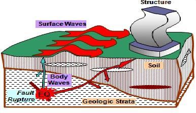

2.3 Effects of Earthquakes on High Rise Buildings When a building experiences earthquake vibrations, its foundation will move back and forth with the ground. These waves or shaking can be great intense, making stress and deflection along the structures moving the upper edges of the buildings deflect from few mm to many cm depends on heights, size and mass of structures. Earthquake zones are uniform whether the building is single storey or multi storey in the regions.
Paulay & priestley propose a theory about the seismic behaviour of masonry infilled frame and a design
Table 1.
The building should be design in such a way that it will allowcertainamountoflateralmovementofthebuilding components to withstand earthquakes shakings. It has been showed that different building at sizes and height arevibrateswithvaryingfrequencies. Wheretheseweremadenexttoeachother,theycreated stresses in both the structures, thus weakened each other, and in many cases caused the failure of both the structures. Bureau of Indian Standards makes clear instruction, in its code IS 4326 that a separation section is to be provided between building. The space left between the adjacent parts of the building or different parts is defined as the separation Permit movement to prevent the shaking or movement during earthquakes”. Further it declares that the height of the building exceeding the 40m shouldcarrydynamicanalysisof the structures to calculate the drift at story and the separationbetweenthedifferentpartsofstructures. However it has to provided sufficient space between adjoining of the building higher than the summation of assumedflexuralofboththebuildingsattheirtop,itmay have sufficient space to shake. When the neighbouring slabcomesintocontactwiththemiddleofthewallsand the column of the adjacent building, as the building elementssuchaswallsand columnsare notdesigned to take additional lateral force caused by the lateral forces comingfromtheadjacentbuildingslabs.
Sucuoglu & erberik studied seismic performance of a three storey unreinforced masonry building which survived in 1992 erzincan earthquake without damage. A certain number of experiments have been performed to know the material or mechanical properties of the masonry walls. A computer program used for the developmentofmodelofmasonryinfillstructureforthe analysisofthestructures.Resultsofperformeddynamic analysis showed that if it satisfies the requirement of seismic code have considerable lateral load resistance bothinelasticandultimatelimitstate. However the performance of dynamic analysis of masonry building shown a satisfactory result by the use of standard codes such as elastic limit states. Masonry wall due to the internal friction shows the closing of energy. However, these entire conclusions were based on the mechanical properties that were obtained by laboratory tests. In other words, validity of these conclusions is dependent on achievement of the same materialproperties.
in
I 33 II 39 III 44 IV 47 V 50 VI 55 3.
Theapplicationofwindforcestoaclosedbuildinginthe formofpressureappliednormaltotheexteriorsurfaces of the building. As the building is covered by cladding when lateral wind force act on the building structures. Wall surface element on the windward side or assumed to take the total wind pressure and are typically designed to span vertically between the roof and floor structures. Roof and floor slabs, considered as rigid planes (called diaphragms), receive the edge loading from the windward wall and distribute the load to the vertical bracing system. Vertical frames or shear walls, acting as vertical cantilevers, receive the loads from the horizontaldiaphragmsandtransferthemtothebuilding foundations.Thefootingmustbeprovidingwithvertical connecting elements for transferring the loads on the ground. Zone wise basic wind speeds m/s Zone Basic wind speed (m/sec) LITERATURE REVIEW
International Research Journal of Engineering and Technology (IRJET) e ISSN: 2395 0056 Volume: 08 Issue: 12 | Dec 2021 www.irjet.net p ISSN: 2395 0072 © 2021, IRJET | Impact Factor value: 7.529 | ISO 9001:2008 Certified Journal | Page264
2.4 Wind Forces
International Research Journal of Engineering and Technology (IRJET) e ISSN: 2395 0056 Volume: 08 Issue: 12 | Dec 2021 www.irjet.net p ISSN: 2395 0072 © 2021, IRJET | Impact Factor value: 7.529 | ISO 9001:2008 Certified Journal | Page265
Smith&carterexaminedmulti storeyinfilledframesfor the case of lateral loading. In the light of experimental results, authors proposed design graphs and design methodbasedonanequivalentstrutconcept.Theirprior necessity is to know behaviour of composite infilled framesunderdamagemodes.Compressionstrut’swidth is greatly effect and it is determined. After determining thedesigncurvesandcrushingstrengththebehaviourof the masonry structures is known. For the rehabilitation and retrofitting of the masonry infill walls can be analysed by using the guide lines of the federal management guideline. Since this is not a code but by using this we can effective built the structures and it is documentanalysisprocedures. Material properties and design criteria for concrete, steel, masonry and lightweight materials are given in separate chapters. As the concrete provision shall be design for the infilled concrete frames. As per this instructionsthatconcreteframeswithinfillwallswillbe constructed in such a manner that the infill and frame should be connected when load is acting. Young’s modulus of elasticity of material and stiffness should be knownpriortoconstruct.
method for infilled frames. Although the masonry infill walls increases the over all lateral stability of the structures under the lateral loading such seismic and wind forces for various parts of the building. Infilled frames behaviour is different with respect to seismic loadandmasonryinfillshowsstructuralfailures.
5. MODELING OF STRUCTURAL
If a structure act by lateral loading system such as earthquake due to their influences, the structure starts vibrating. Whenever the earthquake force act on the structure, it is divided into three forces and is perpendicularto eachotherdirections.Thefirstandthe second are the horizontal forces in direction (x and y) andthethirdverticalforceinthedirection(z).duetothe forces the particle or parts vibrates in all the three directions, the most important force for our consideration is the horizontal forces. Initially the gravity loads are force by the product of mass and time gravity in the vertical direction. Because of the inherent factor of safety used in the design specifications, most structures tend to be adequately protected against vertical shaking. For the structure with the larger span overallstabilityofthestructuresiseffectedwithvertical acceleration. 4.1 Dynamic Analysis Dynamic analysis can be used to determine the design seismic forces and their behaviour at different levels of high rise buildings and subjected with different lateral loading systems for the structural elements to the building As the normal building constructed in the seismicregionofzonesIVandV,ismorethanwhenseen withnormalbuildingheightinzonesIIandIII.Asperthe code for the analysis of the structures for the dynamic analysis from IS CODE can be figure out the type of irregularitiesinthebuilding.
4. METHODOLOGY
The modelling of the building structures for a multi storeybuildingsmakingthefloorplanandrepeatingthe sameplanintheverticaldirection. Modelling features is the stream line analysis model generation, and advanced stimulate seismic systems are listedasbelow: Globalsystemandlocalsystemstemplates Arrangementofshellandframeobjects Geometric section and behaviour is customized andconstitutive Manualoptionsandautomaticmeshingsystem 3D views , plan and elevation assignment and editingfeatures Advance seismic systems for model isolators anddampersforlinkassignment Specificationfornon linearhinges
Smith & coull presented a design method for infilled framebasedondiagonallybracedframecriteria. Asthey shows 3 ways of failure of infill walls, one is the shear, second is the diagonal breaking and the third is the breaking of corner infill. Effective width of diagonal compression is equal to the 1/10 of structural diagonal length. Initially the design should be based on gravity loadings Sucuogluitself.&mcniven studied seismic response of reinforced masonry piers that reveal a shear mode of failure. They have presented two parts after conducting the number of experiment under simultaneous lateral loads. Based on the experimental result certain have been used for the seismic design of masonry and specified codes. They focused on the seismic shear responseofreinforcedmasonrypiers.Asthegravityload and aspect ratios increases the structural piers fails due to the shear. Their more concern about shear design property of masonry piers based on analytical and inventionofmasonrybehaviouratultimatefailure.Their design method was based on diagonal cracking strength of masonry piers. In addition, web reinforcement was usedindesignmethodtoprovidepost crackingcapacity. They concluded that vertical loads have strong effect on bothcrackingandultimate strengthlevel.Moreover,the results of the proposed method, which determined the design shear and the amount of web reinforcement essential for ductile resistance, matched with the experimentalresults.
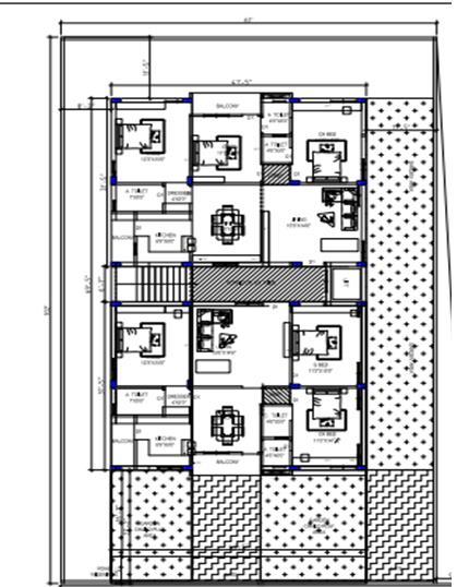
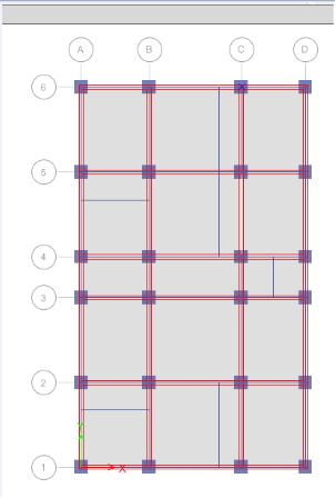
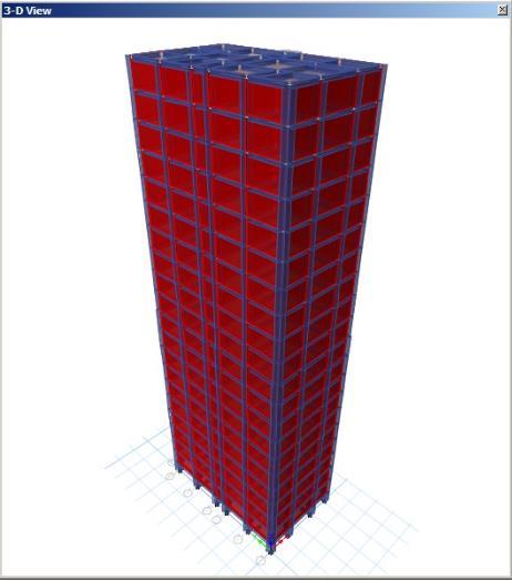
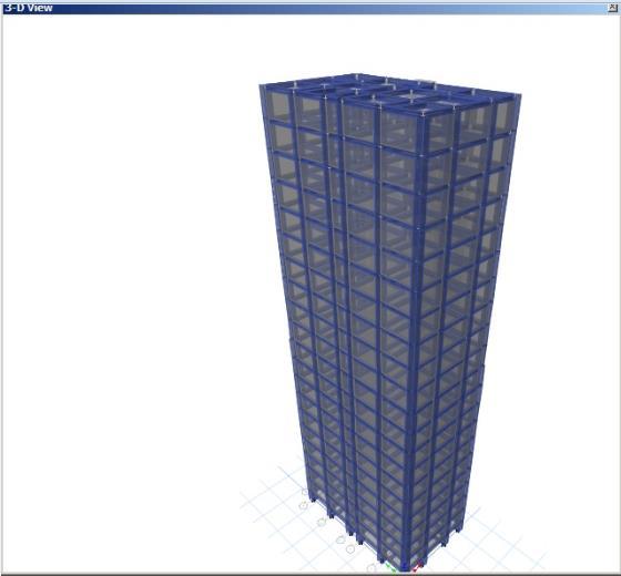
International Research Journal of Engineering and Technology (IRJET) e ISSN: 2395 0056 Volume: 08 Issue: 12 | Dec 2021 www.irjet.net p ISSN: 2395 0072 © 2021, IRJET | Impact Factor value: 7.529 | ISO 9001:2008 Certified Journal | Page266 Figure 5. Typical Floor Plan Figure 6. Showing the grid diagram and 3d model of infill wall structures Figure 7. 3D Model View of Infill Wall Structures Figure 8. 3D Model View of Structures 5.1 DESCRIPTION OF BUILDING DeadloadsconsideredasperIS875(part1) 1987. Structure: G+20 storey building rectangular in plan Plandimensions:12.39mx20.94m. Column size: C750X750mm of M35 grade of concrete from 11th story and above, C900X900mmofM40 gradeofconcretefrom10th storyandbelow. Beam size: B300X450mm of M35 grade of concrete from 11th story and above, B300X600mm of M40 grade of concrete from 10th storyandbelow. Slab thickness: S200mm of M35 grade concrete forallstoreys Stair case: S125mm of M35 grade concrete for allstoreys. Wall: W230mm up to 20th story, parapet wall W115mm Typicalfloorheight:3m Plinthlevelheight:1.5m Floor:G+20story Support:fixed Typeofsoil:Mediumtype(IS:1893) Zone:II
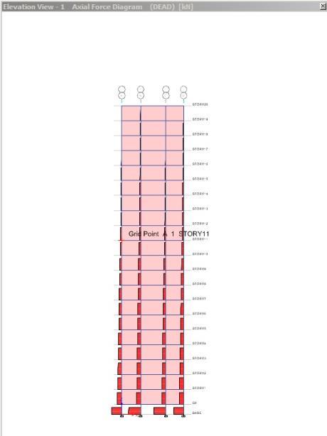
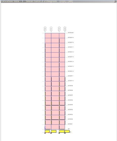
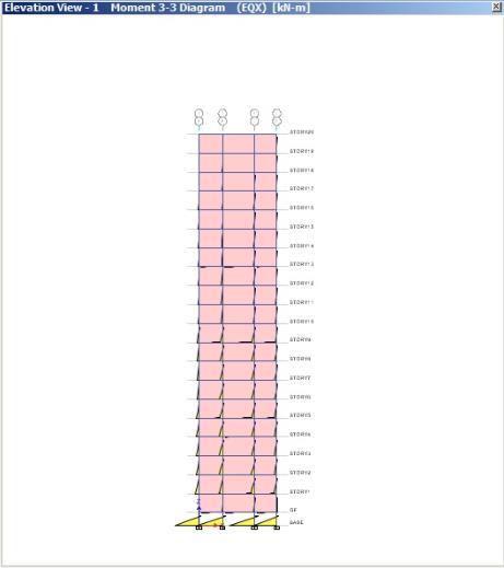
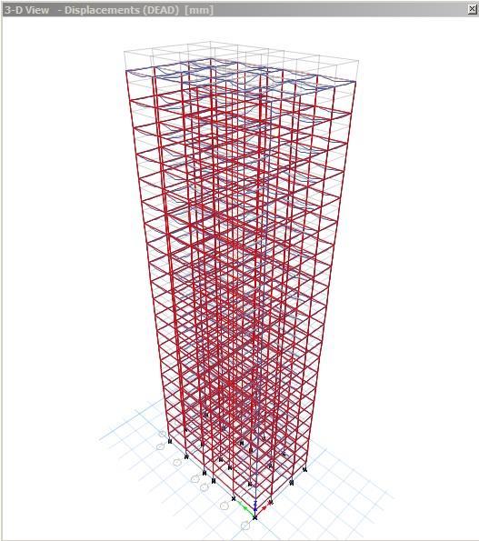
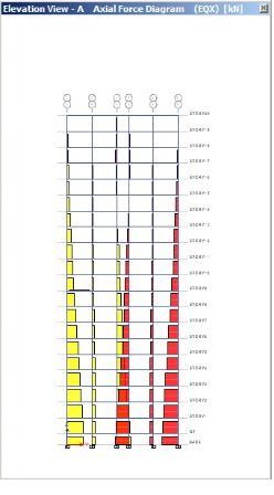
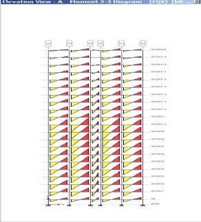
International Research Journal of Engineering and Technology (IRJET) e ISSN: 2395 0056 Volume: 08 Issue: 12 | Dec 2021 www.irjet.net p ISSN: 2395 0072 © 2021, IRJET | Impact Factor value: 7.529 | ISO 9001:2008 Certified Journal | Page267 6. RESULTS AND DISCUSSIONS 6.1 INFILL WALL Axial Force Diagram of Infill Wall with Elevation View 1 and Elevation View A Figure 9. Axial Diagram of Infill Wall with Elevation View 1 and Elevation View A Figure 10. Shear Force Diagram of Infill Wall with Elevation View 1 And Elevation View A Figure 11. Bending Moment Diagram of Infill Wall With Elevation View 1 And Elevation View A Figure 12. Displacement Diagram of Infill Wall with 3D View
International Research Journal of Engineering and Technology (IRJET) e ISSN: 2395 0056 Volume: 08 Issue: 12 | Dec 2021 www.irjet.net p ISSN: 2395 0072 © 2021, IRJET | Impact Factor value: 7.529 | ISO 9001:2008 Certified Journal | Page268 6.2 WITHOUT INFILL WALL Figure 13. axial Diagram of Without Infill Wall with Elevation View A Figure 14. Bending Moment Diagram of without Infill Wall with Elevation View A 7. DISCUSSION OF RESULTS After analysing the high rise building structure with the effect of infill shows the agreeable response on the structural performance, subjected to lateral loading systems. The use of infill walls has an influence on the structural behaviour of the structures. Knowing the valuesofthedisplacement,driftandbaseshearvalues. 1. DISPLACEMENT: The displacements at top story of the building with infill’s wall in zone II reduces by 29.88%alongX directionand24.98%alongY direction. Percentage of displacement in zone II No.Story WallsWithoutInDisplacement%XDirectionInfill % Displacement In WallsWithoutY-DirectionInfill 20th 29.88 24.98 10th 20.11 18.37 2th 6.13 7.85 2. STORY DRIFT: Storey drift for infilled wall model is within permissible limit as per the code provisions. The drift at top story of the building with infill walls in zone II reduces by 30.02% along X direction and 25.63% alongY direction. Percentage of drift in zone II NO.STORY % DRIFT IN X WALLSWITHOUTDIRECTIONINFILL % DRIFT IN Y INFILLWITHOUTDIRECTIONWALLS 20th 30.02 25.63 10th 27.38 41.84 2th 39.36 66.66 3. Base shear: From the results, it is shown that due to infill walls in building the base shear is increased to 25.10% ascomparedtothemodelwithoutinfills Table7.9: Comparison of Hand Calculation Values of Base Shear with Etabs Load Manually Etabs Variation In Percentage % EQX 841.67 888 5.21 EQY 1099.07 1144 3.92 8. CONCLUSIONS The displacements at top story of the building with infill’s wall in zone II reduces by 29.88% alongX directionand24.98%alongY direction. The percentage displacements in X direction without infill walls at stories 20th, 10th and 2th are29.88%,20.11%and6.13%respectively.
computations (Second Edition), CBS Publishers
Afterobservingthedrift,displacementandtime period there is decrease in their values. We can alsonoticethatthebaseshearisincreasingwith theinfillwalls. Therefore, the inclusion of the effect of infill walls in the structural analysis of the buildings reducesthelateralloaddeflectionanddrift.
2.
3.
Storey drift for infilled wall model is within permissiblelimitasperthecodeprovisions.The driftattopstoryofthe buildingwithinfill walls in zone II reduces by 30.02% along X direction and25.63%alongY direction.
Analysis
Imposed
Distributors New Delhi,2004 7. Chug,
IS 456 2000 Code Of Practice For Plain AndReinforcedConcrete. IS 1893(Part1) 2002 Criteria For Earthquake Resistant Design Of Structures IS 875(Part1) 1987 Code Of Practice For Design Loads(Other Than Earthquake) For Buildings And Structures DeadLoads IS 875(Part2)-1987- Code Of Practice For Design Loads(Other Than Earthquake) For Buildings And Structures Loads & Structures, Inc., “ETABS Building & & & R. (2004) RC D.S. PRAKASH RAO the
analysis of structures.
TheFundamentalnaturaltimeperiodforzoneII inX directionandY directionare1.580secand 1.210secrespectively
Studieson
The percentage drifts in X direction without infill walls at stories 20th, 10th and 2th are 30.02%,27.38%and39.36%respectively.
4.
Building top storey displacement, time period and drift is decreases due to the presence of infill walls in the high rise buildings. And the base shear is increased. The behaviour of high risebuildingischangetogreatextentbecauseof theuseofmasonryinfillwalls.
Design UserInterfaceManual,”January2002. 6. Mariopaz Structural Dynamics: Theory
REFERENCES1.
The percentage displacements in Y direction without infill walls at stories 20th, 10th and 2th are24.98%,18.37%and7.85%respectively.
Spectralacc.Coeff.inX directionandY direction are0.860and1.123respectively
5. Computers
The base shear is increased to 25.10% as comparedtothemodelwithoutinfills
International Research Journal of Engineering and Technology (IRJET) e ISSN: 2395 0056 Volume: 08 Issue: 12 | Dec 2021 www.irjet.net p ISSN: 2395 0072 © 2021, IRJET | Impact Factor value: 7.529 | ISO 9001:2008 Certified Journal | Page269
Beams 8. S.J.SHAH DESIGN OF HIGH RISE BUILDING 9.
The percentage drifts in Y direction without infill walls at stories 20th, 10th and 2th are 25.63%,41.84%and66.66%respectively.
for
Integrated