Abstract : Performance of structures under frequently occurring earth quake ground motions resulting in structural damages as well as failures have repeatedly demonstrated the seismic vulnerability of existing buildings, due to their design based on gravity loads only or inadequate levels of lateral forces. This necessitates the need for design based on seismic responses by suitable methods to ensure strength and stability of structures. Shear wall systems are one of the most commonly used lateral load resisting systems in high rise buildings. This study aims at comparing various parameters such as storey drift, storey shear, deflection, etc. of a building under lateral loads based on strategic positioning ofshearwalls. Inthisprojecta parametric model ofsymmetric buildingconfigurationhavebeenselectedfor study, 6 models of different structural configuration have been generated, combining frame and shear walls. Models started with first bare frame model, planar shear wall model with x and y orientation, corner L shaped shear walls and Centralcorewallwithandwithoutopeningsateachsuccessivefloorlevel.Allmathematicalmodelshavebeengenerated in E tabs 2016.All earthquake parameters such as Lateral displacement; inter storey drift ratios, seismic base shear and dynamicparameterssuchasfundamentalnaturaltimeperiods,Modalmassparticipationfactors,fundamentalmodesand modes shapes have been studied in detail. Results have compared with bare frames model with all other models and importantconclusionhasbeendrawn.
Keyword’s: Structural Frames, Response spectrum method, Shear wall INTRODUCTION
Madduru Varshini1 , K.Mallikharjuna Rao2
A Seismic is a sudden slip or displacement of a portion of the earth's crust or plates caused by an abrupt arrival of pressure. The innercore, theouter base, the mantleandthehull arefour significantlayersof the earth, the exterior and the tip of the mantle form a slight layer within the surface. Regardless, the earth has four substantial layers: the inner layer,theoutercentre,themantle,andthehull.Ontheoutside,theexteriorandthetipofthemantleformaslenderlayer ofsoil.Thislayerisunquestionablynotasinglespreadinanycase;therearemultiplecomponentsinvolved,suchasjigsaw coveringtheoutsideoftheplanet.Theykeepgoingslowlyaroundeachother,slidingpasteachother,anddiscoveringeach other.TheseinterconnectingsectionsarecalledthebasicPlatesareknowntotheextentpossible,andtheboundary/edges oftheplates.Quitefarareincludedvariousimperfectionsandanenormousbittheseproblemsemergefarandwidefrom the major earthquakes. Because the edges of the surfaces are disrupted, they slow down through the remainder of the layer keeps working. Finally, when the layer has rotated far sufficient, the boundary/edges detach on one of the defects, andthereisaseismictremor,unquestionablynotasinglespread,itinvolvesseveralsectionssuchasjigsawthatcoverthe outsideoftheearth.Theymovearoundeachotherslowly,wearawayeachotherandexploreeachother.Thebasicplates are called these interconnecting parts, and the borders of the plates are known to the extent possible. Different imperfectionsare used asfaras possible and on Asignificant part of the major earthquakes far and wide originate from theseissues.Untiltheendsofthetectonicplatesaredisrupted,theyslowdownwhiletheotherofthetectonicplatekeeps going. Finally, the boundary/edges detach on one of the defects when the surface has rotated far enough and there is a seismictremor.
M. Tech Scholar1, Associate Professor2, Department of Civil Engineering, ST. Mary’s Group of Institutions Guntur, Andhra Pradesh, India ***
International Research Journal of Engineering and Technology (IRJET) e-ISSN: 2395-0056 Volume: 08 Issue: 12 | Dec 2021 www.irjet.net p-ISSN: 2395-0072 © 2021, IRJET | Impact Factor value: 7.529 | ISO 9001:2008 Certified Journal | Page236 SEISMIC RESPONSE EVALUATION OF REINFORCED CONCRETE STRUCTURAL FRAMES WITH LATERAL LOAD RESISTING ELEMENTS

1.3 FAILURE OF SOFT STOREY Ingeneral,multi celebratedstructuresinmetropolitanurbanareasrequireopentallerfirststoryforleavingofvehiclesor forretailshopping,hugespaceformeetingroomorafinanciallobbyattributabletoabsenceoflevelspaceandsignificant expense. Because of this practical prerequisite, the primary story has lesser quality and solidness when contrasted with upper stories, which are hardened by stone work infill dividers. This trait of building development makes "feeble" or "delicate"storyissuesinmulti storystructures.Expandedadaptabilityoffirststoryresultsinquiteawhile,whichthusly, prompts grouping of powers at second story associations joined by enormous plastic disfigurements. Moreover, a large portion of the vitality created during quake is disseminated by segments of the delicate stories. In this procedure the plasticpivotsareshapedat theclosuresofsections,whichchangethe delicatestory intoaninstrument.Insuchcasethe breakdown is unavoidable. In this manner, the delicate stories merit an uncommon thought in investigation and plan. It has been seen from the overview that the harm is because of breakdown and clasping of segments particularly where stoppingplacesarenotsecuredappropriately.Despitewhatmightbeexpected,theharmisdecreasedimpressivelywhere theparkingspotsaresecuredsufficiently.Itisperceivedthatthissortofdisappointmentresultsfromthe blendofa few othernegative reasons, for example,twist,overthetop massonupper floors, p Δimpactsandabsenceofmalleability in thebasestory.
1.2: EARTHQUAKE ENVIRONMENT EFFECTS
Intheplanet,mostgroundshaking/earthquakeoccuralongthebordersTectonicplatesthey’readdressedtoasinter plate earthquakes.Differenttremorsoccurtothemaximumpracticablewithintheplateitself,calledintra plateearthquakes,in thesameway.Shuddersaremarkedbyseismographscalledtools.Aseismogramisdefinedasthetextthattheyrecorded.
Theseismogramconsistsoftwopartstokeepitimmovableintheearth,afoundationandaweight.Theseismographbase oftenshakesasatremorcausestheearthtoshake,thebodyweight,however,doesn't.Ormaybethespringorstringthatit is dangling from ingests all the turn of events. Thus the differentiation between the moving and enthusiastic part is recorded. The size of a seismic tremor depends upon the size of the issue and the proportion of slip on the blemish; anyway this can't be assessed truly as issues are some place down in the earth. The seismogram accounts made on the seismographs at the outside of the earth are used to choose the power of tremor. A short line with fewer pieces of crisscrossleadstoasmallquakeandalengthylinewithawidenumberofareasofcrisscross indicateanimmensequake. Thedurationofthelineontheseismographdependsonthesizeofthedeficiencyandtheline'swigginessdependsonthe deficiency'smeasureofoversight.
Ecological impacts of tremor are the impacts of a quake on the common habitat, including surface blame, structural inspiration and subsidence, torrents, soil liquefactions, soil reverberation, avalanches and soil dissatisfaction, either legitimatelyrelatedtothecauseoftheseismictremororincitedbytheshakingoftheearth.Thesearecustomaryfeatures rendered in the vicinity of both regularly documented and diagrammed in progressive cases, recorded in chronicled accountsallthetimeandguaranteedinthestaticgraphicrecord(paleearthquakes).Bothsurfacedistortionandblaming andshaking relatedgeographicalimpacts(e.g.,soilliquefaction,avalanches)leavechangelessengravingsintheearth,yet additionally significantly influence human structures. Besides, submerged issue cracks and seismically activated avalanchescanproduce damaging torrent waves. EEEsspeak to a noteworthy well spring of peril,particularly(however not only) during huge quakes. This waswatched forinstanceduring pretty much calamitous seismic occasions asof late happenedinaltogetherdifferentpiecesoftheworld.
International Research Journal of Engineering and Technology (IRJET) e-ISSN: 2395-0056 Volume: 08 Issue: 12 | Dec 2021 www.irjet.net p-ISSN: 2395-0072 © 2021, IRJET | Impact Factor value: 7.529 | ISO 9001:2008 Certified Journal | Page237
1.1 TYPES OF EARTHQUAKE
International Research Journal of Engineering and Technology (IRJET) e-ISSN: 2395-0056 Volume: 08 Issue: 12 | Dec 2021 www.irjet.net p-ISSN: 2395-0072 © 2021, IRJET | Impact Factor value: 7.529 | ISO 9001:2008 Certified Journal | Page238
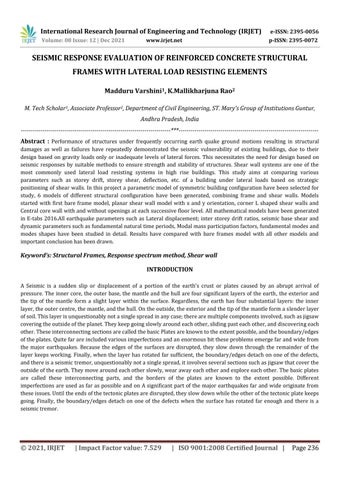
Figure 1. Soft Storey Failure in Bhuj 1.4 SHEAR WALLS
2. LETIRATURE VIEW
Foralongtime,numerousresearchstudiesandexperimentshavebeencarriedoutaroundtheworldtoexplainortestthe effectsofseismicforcesonexistingRCbuildingsinhighseismiczones. An examination on "Seismic Performance Evaluation of Multi celebrated RC confined structures with Shear divider" by SHAIKKAMALMOHAMMEDAZAMAcorrelationofauxiliaryconductasfarasquality,solidnessanddampingattributesis finished by masterminding shear dividers at various areas/setups in the basic surrounding framework. The adaptable (responserunassessment)similarlyasin adaptable(nonlinearstaticweaklingexamination)assessmentsarefinishedfor the appraisal of seismic execution. The numerical models to be explicit, six praised, twelve commended, twenty four celebrated and thirty six commended second contradicting RC encompassed structures, having the plan estimations of 30mx20mwithgulflengthof5minthetwoheadingsandfloorheightof3mareconsideredintheassessment.Thegame plan of shear divider has vital impact on even quality in taller structures while it has less effect on equal robustness in tallerstructures.Thecourseofactionofsheardividerhasbasicimpactonsidelongstrengthinstructuresofshorterheight while it has less effect on level quality. The effect of shear dividers is colossal to the extent the damping properties and period at the introduction point for tall buildings. The fundamental arrangement of model 8 has indicated dominating essentialexecutionwithrespecttoboththeimmovabilityandqualityintheadaptablesimilarlyasinthenonlinearrange uptoexecutionpoint.Themodel 7,inanycaseinlikemannerhascloserhelperexecutiontothemodel 7,withrespectto both the robustness and quality in the adaptable similarly as in the nonlinear range up to execution point. Subsequently thehelpergameplansofmodels7and8notsimplygavetheimprovementinsidelongweightrestrictionlimityetalsothe extension in even strength. The packaging without the shear dividers but] with stone work infill showed shoddy helper execution to the extent both the immovability and quality. Course of action of shear dividers uniformly in the uttermost
Inbuildingadvancement,aninflexibleverticalstomachpreparedformovinglevelforcesfromoutsidedividers,floors,and housetops to the ground foundation toward a way comparing to their planes. Models are the braced strong divider or vertical help. Flat powers achieved by wind, seismic tremor, and unbalanced settlement loads, despite the greatness of structure
Verticalcomponentsofconcretewallsareoftheresistivesystemforhorizontalpower.Inordertoovercometheimpactof lateral forces on a structure, shear walls are built. Shear dividers are straight outer dividers in private construction that usually structure a crate that provides the entire sidelong support for the structure. At the point of structuring shear Dividersandproperlymade,andtheywillhavetheconsistencyandstrengthtoopposetheflatforces.
This is a direct static examination. This strategy describes a way to deal with talk with the effect of shudder ground developmentwhengameplanofforcesarefollowuponastructure,throughaseismicarrangementresponseextend.This strategy acknowledges that the structure responds in its key mode. The congruity of this procedure is connected in numerous development gauges by applying parts to speak to higher structures with some higher modes, and for low degreesofbending.Differentcodesapplymodificationfactorsthatdeclinethearrangementpowerstotalkaboutimpacts dueto"yielding"theframework. Inthesimilarstatictechnique,theequalforceequivalenttothestructurepremiseseismictremorisappliedstatically.The tantamountflatpowersateachstorylevelThebaseelementofthestructureItisspokentoasd(inmeters)attheplinth level along the bearing of horizontal forces and the tallness of the structure from the assistance is spoken to as h (in meters).
AsperIS1893 2002thisexaminationcanbeperformedbyutilizingthearticulation QS= WhereQs=LateralLoadDistributionatStorey Wi=SeismicStructuralMass HI=TheFrameworkHeight VB=DesignBaseShear,whichcanbedeterminebyusing,VB=Ah W Ah= Z=Zone
3. METHODS OF ANALYSIS
3.1: EQUIVALENT STATIC ANALYSIS
R=ResponseI=Importancefactor,factor,reductionfactor, Sa /g=Averageresponseaccelerationcoefficient
International Research Journal of Engineering and Technology (IRJET) e-ISSN: 2395-0056 Volume: 08 Issue: 12 | Dec 2021 www.irjet.net p-ISSN: 2395-0072 © 2021, IRJET | Impact Factor value: 7.529 | ISO 9001:2008 Certified Journal | Page239
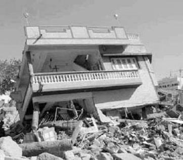
3.2 RESPONSE SPECTRUM: The real time history record is needed in order to determine the seismic analysis and schedule of a structure to be employed in a particular region. It's ridiculous, in any case, to presume to have such records in every single area. In addition, itisimpossibleto completetheseismicanalysisofstructurespracticallydependingonthepinnacle estimateof thespeedingupofthegroundasthestructuretheresponseisbasedontherecurrenceofthemovementofthesoiland its own specific properties. The range of quake reactions is the most common method in the seismic investigation of structurestosolvetheabovechallenges.TheIndianstandardsconfigurationsare:1893(Part1) 2002codeforresponse range study of multi story construction is also summarized, according to Seems.The Approach Range Bend is given in accordancewithIS1893 2002as
second contradicting edges and obviously interconnected regularly inverse way forming the middle will have better seismicexecutiontotheextentqualityandimmovability.
International Research Journal of Engineering and Technology (IRJET) e-ISSN: 2395-0056 Volume: 08 Issue: 12 | Dec 2021 www.irjet.net p-ISSN: 2395-0072 © 2021, IRJET | Impact Factor value: 7.529 | ISO 9001:2008 Certified Journal | Page240 Chart1 Responsespectrumcurvegraph
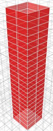
Model IV Modelassameas Model I butPlanarshearwallsinYdirectionareprovidedattheinnercornersofthe3D buildingmodel. Model V Modelassameas Model I butacentralcorewallisprovided. Model VI Modelassameas Model V shearwallopeningsareprovidedateachfloorleveltoaccesslift.
3.3 STRUCTURAL MODELLING TotheFEMmodellingsoftwarecalledETABS2016versionhavebeenusedto completetheSeismicanalysisprocess,after static and dynamic analysis, parameters like, modes shapes, lateral displacement, storey forces, inter storey drift have consideredastheparametersforthecurrentstudy, Themodelsforanalysisareasfollows: Model I Modelwithbareframe(IncludingweightofBrickwall). Model II Modelassameas Model I butL shapedshearwallsareprovidedattheinnercornersofthe3Dbuildingmodel.
Usually,anSDOF system responseisregulatedby timespaceor resectionarea examination,and most extreme reactions arechosenforagivenperiodoftimeoftheframework.ForallpossibletimeperiodsoftheSDOFsystem,thisprocedureis carried out. Last plot with framework timeframe on x pivot and reaction amount on y hub is the necessary reaction spectra 103 relating to indicated damping proportion and information ground movement. Same procedure is completed withvariousdampingproportionstoacquirebyandlargereactionspectra.
Model III Modelassameas Model I butPlanarshearwallsinXdirectionareprovidedattheinnercornersofthe3D buildingmodel.
3.2 RESPONSE SPECTRUM METHOD
Explanation spectra are curves that are graphed between the maximum response to the defined earthquake ground movementoftheSDOFsystemanditstimespan(orfrequency).Foragivendampingproportion,theresponserangecan bedecipheredasthelocusofthemostseverereactionofanSDOFsystem.Inthisway,interactionspectrahelpstogetthe pinnacleauxiliaryreactionsunderdirectrange,whichcanbeusedtoacquiresidelongpowersproducedinstructuredue tothequakealongtheselines,enablingstructurestopreparetremorsecurely.
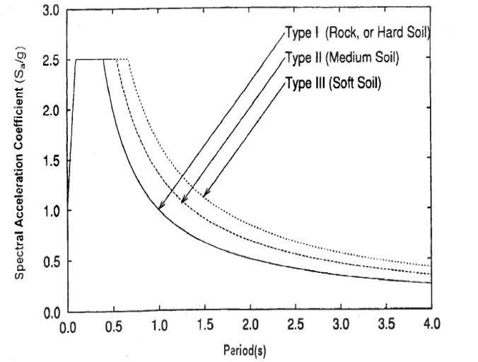
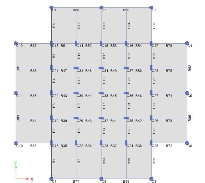
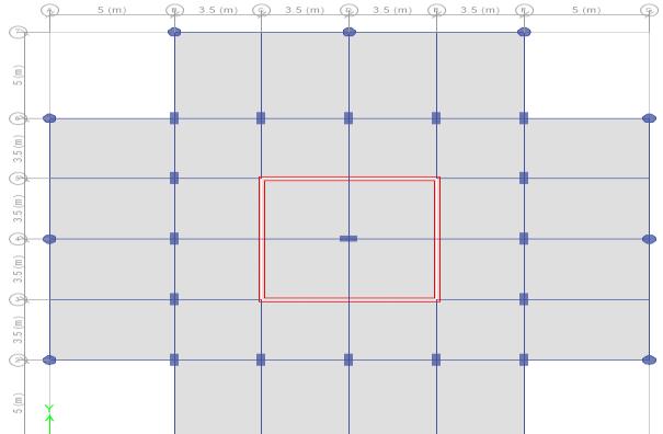
International Research Journal of Engineering and Technology (IRJET) e-ISSN: 2395-0056 Volume: 08 Issue: 12 | Dec 2021 www.irjet.net p-ISSN: 2395-0072 © 2021, IRJET | Impact Factor value: 7.529 | ISO 9001:2008 Certified Journal | Page241 MODELLING DETAILS 1. Frametype:SpecialMomentResistingFrame(SMRF) 2. Building:G+10 3. TypicalStoreyHeight:3.2m 4. BottomstoreyHeight:4m 5. PlanDimensions:24.0mx24.0m 6. SizeofColumns:350mmx700mm 7. SizeofColumns:500mmdiameter 8. SizeofBeams: 350mmx550mm 9. Slabthickness:125mm 10. UnitweightofRCC:25KN/m2 11. UnitweightofMasonry:20KN/m2 12. LiveLoadIntensityonFloor:3.5KN/m2 13. WeightofFloorfinish:1.0KN/m2 14. ThicknessofWall:230mm 15. HeightofParapet:1m 16. SeismicZone:V,Z=0.36 17. Importancefactor:1.5 18. Responsereductionfactor:5 19. Soiltype:Medium 20. Shearwallthickness:230mm Followingarethedrawingswhichwillindicatethedetailexplanationaboutmathematicalmodelstakenforstudy. Figure 2.Plan of the Building at Bottom Storey Level
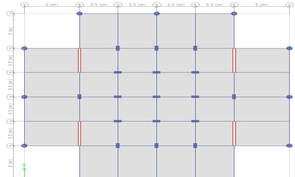
International Research Journal of Engineering and Technology (IRJET) e-ISSN: 2395-0056 Volume: 08 Issue: 12 | Dec 2021 www.irjet.net p-ISSN: 2395-0072 © 2021, IRJET | Impact Factor value: 7.529 | ISO 9001:2008 Certified Journal | Page242 Figure 3. Plan of the Building at Typical Storey Level Figure 4. Plan View of Model II Figure 5 .Plan of the Building at Bottom Storey Level
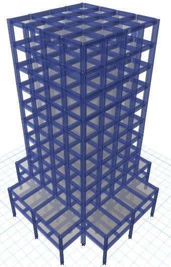
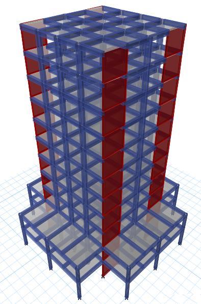
International Research Journal of Engineering and Technology (IRJET) e-ISSN: 2395-0056 Volume: 08 Issue: 12 | Dec 2021 www.irjet.net p-ISSN: 2395-0072 © 2021, IRJET | Impact Factor value: 7.529 | ISO 9001:2008 Certified Journal | Page243 Figure 6. 3D View of Model III Figure 7 .Plan of the model III Figure 8. 3D View of Model III 4. RESULTS& DISCUSSIONS 4.1 GENERAL Forthissection,afterevaluatingthemodelsandeffects,wewillanalyzethematterweobtainedfromETABSinatabular formandlinechartforbettercomprehension. Theprocessmeasureshavebeenanalyzedandtheeffectsofthesoftwareprogramhavebeenextracted. 4.2 LATERAL STOREY DISPLACEMENT: Storey displacement is the lateral drift of the structure caused by lateral force. This parameter is one of the important parametersfor lateral stabilityof the structures; no other parameter will give the better understanding that thisone. As
International Research Journal of Engineering and Technology (IRJET) e-ISSN: 2395-0056 Volume: 08 Issue: 12 | Dec 2021 www.irjet.net p-ISSN: 2395-0072 © 2021, IRJET | Impact Factor value: 7.529 | ISO 9001:2008 Certified Journal | Page244 far as possible the displacement must be within the limits as specified by codal provision, otherwise leading to sever damagetobuildingssystem. Table 1: Displacement in longitudinal Direction Roof Displacements in mm STOREY MODEL 1 MODEL 2 MODEL 3 MODEL 4 MODEL 5 MODEL 6 UX UY UX UY UX UY UX UY UX UY UX UY 11 32.6 32.0 22.1 22.1 25.2 32.9 31.8 25.7 16.4 15.5 17.2 16.4 10 31.6 30.9 20.4 20.4 23.5 32.1 31.0 23.9 14.8 14.1 15.6 14.9 9 30.1 29.3 18.5 18.5 21.6 30.7 29.7 22.0 13.1 12.5 13.9 13.3 8 28.0 27.1 16.4 16.4 19.5 28.6 27.7 19.7 11.4 10.9 12.2 11.6 7 25.4 24.4 14.2 14.2 17.0 26.1 25.3 17.2 9.7 9.2 10.3 9.9 6 22.4 21.4 11.8 11.8 14.3 23.1 22.5 14.4 7.9 7.6 8.5 8.2 5 19.2 18.1 9.3 9.3 11.4 19.8 19.3 11.5 6.2 5.9 6.7 6.4 4 15.6 14.4 6.9 6.9 8.5 16.1 15.7 8.5 4.6 4.4 5.0 4.8 3 11.8 10.6 4.6 4.6 5.7 12.1 12.0 5.6 3.1 3.0 3.4 3.3 2 8.0 7.0 2.5 2.5 3.1 8.2 8.1 3.1 1.8 1.7 2.0 1.9 1 4.4 3.7 1.0 1.0 1.2 4.6 4.5 1.2 0.8 0.8 0.9 0.9
International Research Journal of Engineering and Technology (IRJET) e-ISSN: 2395-0056 Volume: 08 Issue: 12 | Dec 2021 www.irjet.net p-ISSN: 2395-0072 © 2021, IRJET | Impact Factor value: 7.529 | ISO 9001:2008 Certified Journal | Page245 Chart 2. Displacement in Longitudinal Direction. Table 2. Displacement in Transverse Direction. Roof Displacements in mm STOREY MODEL 1 MODEL 2 MODEL 3 MODEL 4 MODEL 5 MODEL 6 UX UY UX UY UX UY UX UY UX UY UX UY 11 32.6 32.0 22.1 22.1 25.2 32.9 31.8 25.7 16.4 15.5 17.2 16.4 10 31.6 30.9 20.4 20.4 23.5 32.1 31.0 23.9 14.8 14.1 15.6 14.9 9 30.1 29.3 18.5 18.5 21.6 30.7 29.7 22.0 13.1 12.5 13.9 13.3 8 28.0 27.1 16.4 16.4 19.5 28.6 27.7 19.7 11.4 10.9 12.2 11.6 7 25.4 24.4 14.2 14.2 17.0 26.1 25.3 17.2 9.7 9.2 10.3 9.9 6 22.4 21.4 11.8 11.8 14.3 23.1 22.5 14.4 7.9 7.6 8.5 8.2 5 19.2 18.1 9.3 9.3 11.4 19.8 19.3 11.5 6.2 5.9 6.7 6.4 4 15.6 14.4 6.9 6.9 8.5 16.1 15.7 8.5 4.6 4.4 5.0 4.8 3 11.8 10.6 4.6 4.6 5.7 12.1 12.0 5.6 3.1 3.0 3.4 3.3 2 8.0 7.0 2.5 2.5 3.1 8.2 8.1 3.1 1.8 1.7 2.0 1.9 1 4.4 3.7 1.0 1.0 1.2 4.6 4.5 1.2 0.8 0.8 0.9 0.9 1161 0.0 10.0 20.0 30.0 40.0storeyofLevel Displacement in mm Model-1 Model-2 Model-3 Model-4 Model-5 Model-6


10
OF
Table
Model-1 Model-2 Model-3 Model-4 Model-5 Model-6
4.3 STOREY DRIFT
International Research Journal of Engineering and Technology (IRJET) e-ISSN: 2395-0056 Volume: 08 Issue: 12 | Dec 2021 www.irjet.net p-ISSN: 2395-0072 © 2021, IRJET | Impact Factor value: 7.529 | ISO 9001:2008 Certified Journal | Page246
MODEL1 MODEL2 MODEL3 MODEL4 MODEL5 MODEL6 STOREY DRIFTX DRIFTX DRIFTX DRIFTX DRIFTX DRIFTX 11
The higher the drift, the greater the probability that harm will occur. Peak inter story drift values greater than 0.06 indicate serious harm, whereas values greater than 0.025 indicate that the harm may be sufficiently serious to pose a serious threat to human safety. Values in excess of 0.10 indicate probable building collapse. According to I.S 1893 2002 permissiblestoreydriftisequalsto0.004timesheightofstorey. 3. Storey Drift in Longitudinal Direction DRIFT % STOREY HEIGHT 0.00034 0.00056 0.00056 0.00029 0.00050 0.00050 0.00058 0.00061 0.00063 0.00052 mm
IN
STOREY
0.00052
0.00053 1197531 0.0 10.0 20.0 30.0 40.0 storeyofLevel Displacement in
Chart 3. Displacement in Transverse Direction it can be seen from above figures, the displacement of the stories of structures is reduced by developing MODEL 2,4,5,6.Thedisplacement in Model 2Hasbeen reduced by32.22%incomparisonofModel 1,Model 3has beenreduced to22.7%.Model 4hasbeenreducedby2.45%,Model 5hasbeenreducedby49.7%,Model 6hasbeenreducedby47.24%. Inotherwords,thereactionofthestructuresuchasvelocityandaccelerationcanbereducedbyconstructingtheMODEL 2,3,4,5,6anditisthecauseofdisplacementreduction. MODEL 2 and MODEL 3 reveals the same results when we compare with MODEL 1, therefore it can be stated that, orientationofshearwallswillplayamajorruleindesigningseismicresistantstructures.ModelswithL shapesshearwalls shows better results than any other, therefore arranging shear wall away from the rigid centre will enhance the lateral stabilityofthestructureandcanconsiderablyreducetheseismichazardous. Modelswithcore wallsand core wallsopeningsareshowing thesame results,henceit canbestated that, openinginlift elevator,doesn’tmakemuchdifferenceonoverallperformanceofthebuildingsystems. Comparisonismadealonglongitudinaldirectiononly.Transversedirectioncomparisoncanalsobemadeandresultscan becompared,sincethebuildingissymmetricalalongbothorthogonaldirections,onlylongitudinaldirection’scomparison hasmade.


International Research Journal of Engineering and Technology (IRJET) e-ISSN: 2395-0056 Volume: 08 Issue: 12 | Dec 2021 www.irjet.net p-ISSN: 2395-0072 © 2021, IRJET | Impact Factor value: 7.529 | ISO 9001:2008 Certified Journal | Page247 9 0.00079 0.00067 0.00071 0.00074 0.00054 0.00056 8 0.00094 0.00072 0.00080 0.00090 0.00055 0.00057 7 0.00106 0.00076 0.00087 0.00102 0.00056 0.00058 6 0.00114 0.00078 0.00091 0.00111 0.00054 0.00057 5 0.00121 0.00077 0.00093 0.00119 0.00051 0.00054 4 0.00126 0.00073 0.00090 0.00125 0.00047 0.00050 3 0.00124 0.00064 0.00079 0.00124 0.00040 0.00044 2 0.00111 0.00049 0.00061 0.00113 0.00032 0.00035 1 0.00111 0.00025 0.00030 0.00113 0.00019 0.00022 Chart 4. Drift in Longitudinal Direction Table 4. Storey Drift in Transverse direction. STOREY DRIFT IN % OF STOREY HEIGHT MODEL1 MODEL2 MODEL3 MODEL4 MODEL5 MODEL6 STOREY DRIFTINY DRIFTY DRIFTINY DRIFTINY DRIFTINY DRIFTINY 11 0.00039 0.00056 0.00031 0.00058 0.00046 0.00047 10 0.00061 0.00061 0.00055 0.00065 0.00049 0.00050 9 0.00081 0.00066 0.00078 0.00074 0.00051 0.00053 8 0.00096 0.00072 0.00095 0.00082 0.00052 0.00054 7 0.00107 0.00076 0.00108 0.00089 0.00053 0.00055 11975310.00000 0.00020 0.00040 0.00060 0.00080 0.00100 0.00120 0.00140 storeyofLevel Drift in % Model-1 Model-2 Model-3 Model-4 Model-5 Model-6


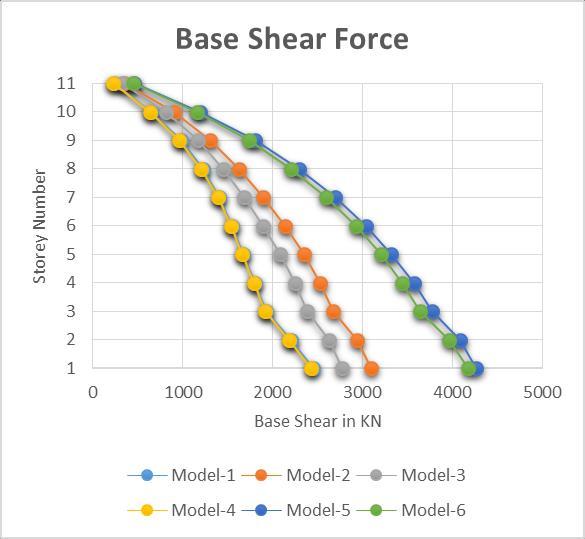
International Research Journal of Engineering and Technology (IRJET) e-ISSN: 2395-0056 Volume: 08 Issue: 12 | Dec 2021 www.irjet.net p-ISSN: 2395-0072 © 2021, IRJET | Impact Factor value: 7.529 | ISO 9001:2008 Certified Journal | Page248 6 0.00115 0.00078 0.00117 0.00093 0.00052 0.00054 5 0.00122 0.00077 0.00125 0.00094 0.00049 0.00052 4 0.00126 0.00073 0.00131 0.00090 0.00045 0.00048 3 0.00118 0.00064 0.00128 0.00079 0.00039 0.00042 2 0.00102 0.00049 0.00113 0.00061 0.00030 0.00034 1 0.00093 0.00025 0.00115 0.00029 0.00019 0.00022 Chart 5. Drift in Transverse Direction MODEL 1,MODEL 3andMODEL 4areshowingapproximatelysameresultsasitcanbeseenfromchartsandtables,when weaddlateralloadresistingelementlikeshearwallsandcentralcorewalls,thestoreydriftconsiderablyreduced,when wecomparemodel2,5,and6withmodel1and3,thepercentageofreductionofinterstoreydriftsare,32.17%,57.85% and 55.37%.Therefore from charts reveals that, core wall and L shapes shear wall will considerably enhance the Fromperformance.thestoreydriftanalysis itcanbeseenthat,higherbasedimensioncanconsiderablyreducethedrift%inturnmake the structure more earthquake resistible and efficient enough in transferring the inertia forces induced due to Lateral Allloads.the drift values are within the permissible limits specified by IS1893 2002. Bare frame shows very flexible performance. 4.4 BASE SHEAR: Baseshearisthecumulativeeffectoflateralforcesofeachparticularstoreyatthebaselevelduetoseismicactivities.Base shearforcevariousmodelshavebeentabulatedfallows. storeyofLevel11109876543210.000000.000200.000400.000600.000800.001000.001200.00140Driftin%Model-1Model-2Model-3


International Research Journal of Engineering and Technology (IRJET) e-ISSN: 2395-0056 Volume: 08 Issue: 12 | Dec 2021 www.irjet.net p-ISSN: 2395-0072 © 2021, IRJET | Impact Factor value: 7.529 | ISO 9001:2008 Certified Journal | Page249 Table 5. Base shear in KN in Longitudinal Direction. BASE SHEAR IN X AND Y DIRECTION KN MODEL 1 MODEL 2 MODEL 3 MODEL 4 MODEL 5 MODEL 6 STOREY Vx Vy Vx Vy Vx Vy Vx Vy Vx Vy Vx Vy 11 237 249 353 353 323 229 231 324 456 460 448 447 10 654 677 901 902 816 632 638 812 1192 1206 1159 1168 9 983 1005 1310 1312 1177 950 963 1165 1801 1827 1738 1769 8 1226 1241 1628 1630 1452 1186 1208 1432 2295 2335 2208 2263 7 1405 1414 1899 1902 1687 1357 1391 1659 2699 2750 2596 2669 6 1547 1555 2143 2145 1900 1493 1536 1866 3036 3098 2926 3009 5 1675 1686 2355 2358 2087 1615 1666 2048 3325 3394 3209 3298 4 1802 1818 2533 2536 2248 1735 1791 2207 3572 3645 3447 3543 3 1926 1944 2679 2682 2385 1854 1912 2343 3772 3847 3638 3742 2 2205 2226 2942 2945 2635 2127 2186 2593 4087 4163 3961 4065 1 2448 2462 3100 3104 2776 2369 2425 2735 4268 4344 4172 4257 Chart 6. Base shear in Longitudinal Direction
4.5 Modal Analysis Results. Modal analysis includes the fundamental natural time period of the structure, Modal Mass participations, and Mode shapes.Theseresultswillelaboratethevibrationanalysisofthebuildingsystemsanditsresponsetoseismicloadings Table 6. Modal analysis results. BuildingModelNo Mode periodTime % of Modal Mass participation Sec TranslationX TranslationY Z Torsion Model 1 1 1.25 74.4 0 0 2 1.223 0 72.2 0 3 1.019 0 0 61 Model 2 1 0.793 63.9 0 0 2 0.793 0 63.11 0 3 0.48 0 0 50 Model 3 1 1.273 0 74.47 0 2 0.918 64.26 0 0 3 0.761 0 0 53.36 Model 4 1 1.235 75.05 0 0 2 0.933 0 63.9 0 111 0 1000 2000 3000 4000 5000NumberStorey Base Shear Force in KN Base Shear Force Model-1 Model-2 Model-3 Model-4 Model-5 Model-6
As it can be seen from tables and charts that, MODEL 1, MODEL 3and MODEL 4 are showing nearly same base shear results,thoughitcanbestatedthat,type,shapeandorientationofshearwallsinMODEL 3andMODEL 4arenotshowing muchstrength,theseareassameasMODEL 1.WhenwecompareMODEL 2withMODEL 1,MODEL 3andMODEL 4,this modelshowshugestrengthaswellasstiffness. MODEL 5 and MODEL 6 are considerably showing highest base shear values among all the models, therefore, core walls playsavitalruletostiffenthebuildingsystemsverticallyoritmayactasverticalstiffeners. corewallsateachfloor,doesnotmakeanydifferencewhenseismicforcesactonthestructures.
International Research Journal of Engineering and Technology (IRJET) e-ISSN: 2395-0056 Volume: 08 Issue: 12 | Dec 2021 www.irjet.net p-ISSN: 2395-0072 © 2021, IRJET | Impact Factor value: 7.529 | ISO 9001:2008 Certified Journal | Page250 Chart 7. Base shear in Transverse Direction
Successiveopeningsin


International Research Journal of Engineering and Technology (IRJET) e-ISSN: 2395-0056 Volume: 08 Issue: 12 | Dec 2021 www.irjet.net p-ISSN: 2395-0072 © 2021, IRJET | Impact Factor value: 7.529 | ISO 9001:2008 Certified Journal | Page251 3 0.783 0 0 52.87 Model 5 1 0.565 61.68 0 0 2 0.546 0 61.87 0 3 0.325 0 0 74.82 Model 6 1 0.589 62.5 0 0 2 0.567 0 62.69 0 3 0.361 0 0 73.9 Chart 8. Fundamental natural time period according to no of modes. Chart 9. % of Modal Mass participation in X direction. 210 0 1 2 3 4 SECINPERIODTIMEMODE NUMBER Fundamental Natural time period and fundamental modes Model-1 Model-2 Model-3 Model-4 Model-5 Model-6 10 1 2 3%INPARTICIPATIONMASSMODAL MODE NUMBER Model differentParticipationMassinmodes Model-1 Model-2 Model-3 Model-4 Model-5 Model-6


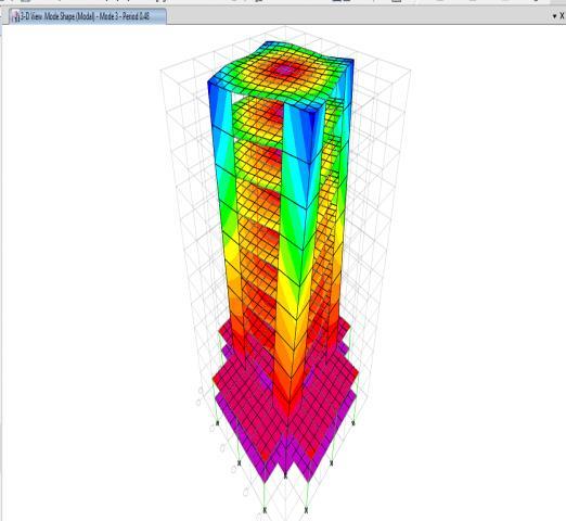
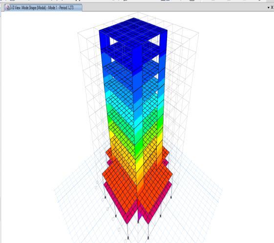
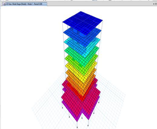
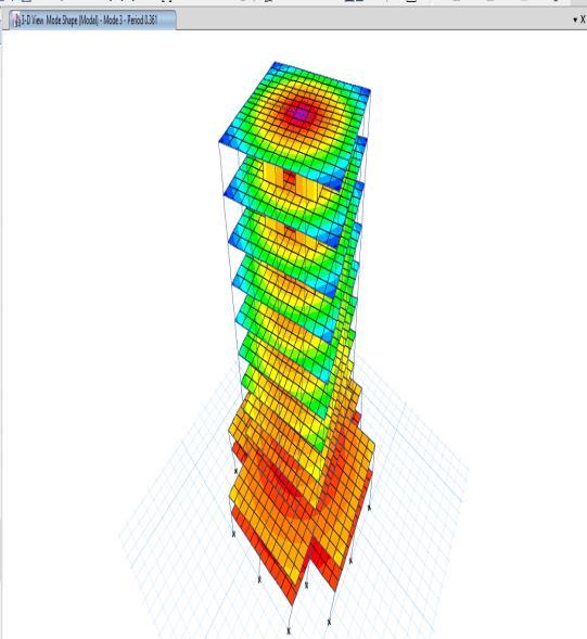
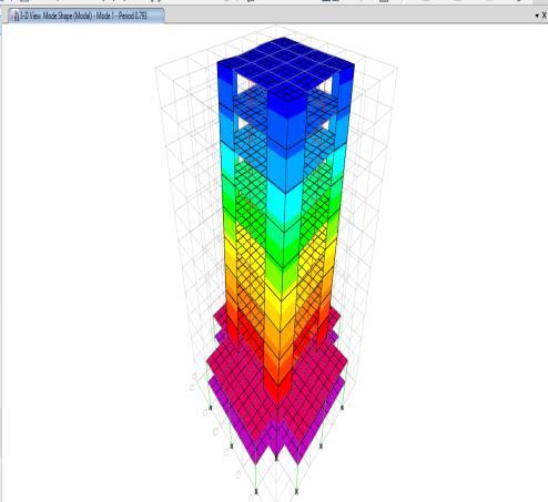
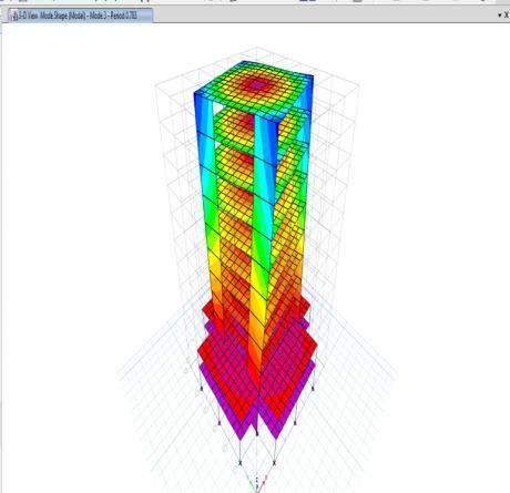
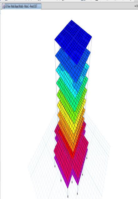
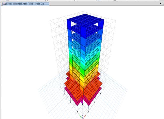
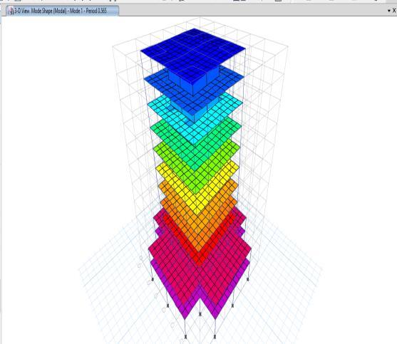
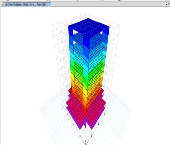
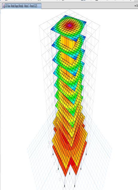
4.6. MODE SHAPES: Mode shapes are nothing but the sudden behaviour of the building systems due to lateral forces, for various models the modesshapesaretabulatedasfallows. Model Mass Participation in different modes Model-1 Model-2 Model-3 Model-4 Model-5 Model-6 Chart Title Model-1 Model-3 Model-4 Model-5 Model-6 Model-2
Chart 11. % of Modal Mass participation in Z direction (Torsion). Abovechartsandtablesrevealsseveralthingswhichbefallowedas.
10 1 2 3 MASSMODAL %INPARTICIPATION MODE NUMBER
The value of T depends on the building flexibility and mass; more the flexibility and mass, the longer is the period. The maximumtimeperiodisinMODEL 1infirstmodeandminimumtimeperiodisinMODEL 5and6infirstmode.Therefore onecansaythatMODEL 5and6havemoreflexibilitywhencomparedtoothermodels.
When we add shear walls in different shapes and at different locations, they substantially decrease the fundamental time periodofthestructureandinturnincreasesthestiffnessandthusoveralllateralstabilitywillbeenhanced. From the modal mass participation investigation it can be seen that, majority of the models are showing good mass participation in fundamental modes, and majority of models have got 1 mode shape as X translation, 2 mode shape as Y translationand3modeshapeasTorsionwhichtotallysatisfyingtherequirementsofIS 1893 2002.
10 1 2 3TITLEAXIS AXIS TITLE
International Research Journal of Engineering and Technology (IRJET) e-ISSN: 2395-0056 Volume: 08 Issue: 12 | Dec 2021 www.irjet.net p-ISSN: 2395-0072 © 2021, IRJET | Impact Factor value: 7.529 | ISO 9001:2008 Certified Journal | Page252
Placingshearwallisveryimportant,incorrectlocationofshearwallsmayleadstoextratorsionalmoments,whichtotally effecttheoverallperformanceofbuildingsystems,whichcanleadtodisasterduringseismicthreatening.
Chart 10. % of Modal Mass participation in Y direction.


International Research Journal of Engineering and Technology (IRJET) e-ISSN: 2395-0056 Volume: 08 Issue: 12 | Dec 2021 www.irjet.net p-ISSN: 2395-0072 © 2021, IRJET | Impact Factor value: 7.529 | ISO 9001:2008 Certified Journal | Page253 Figure 9. Model 1 X translations Figure 10. Model-1 Y translations Figure 11. Model 1 Torsion

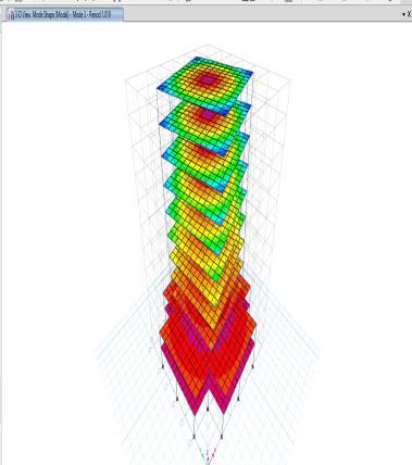


International Research Journal of Engineering and Technology (IRJET) e-ISSN: 2395-0056 Volume: 08 Issue: 12 | Dec 2021 www.irjet.net p-ISSN: 2395-0072 © 2021, IRJET | Impact Factor value: 7.529 | ISO 9001:2008 Certified Journal | Page254 Figure 12. Model 2X translations. Figure 13. Model-2Y translations.

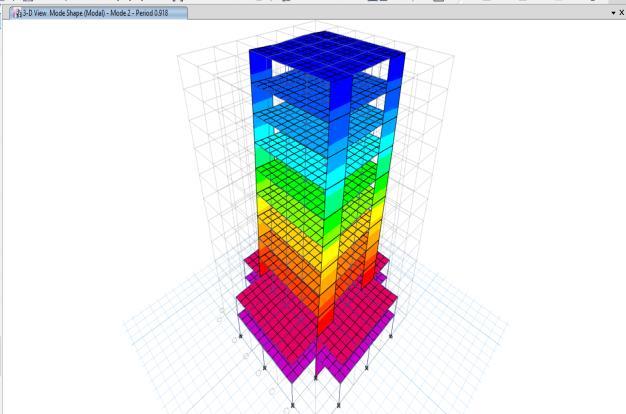


International Research Journal of Engineering and Technology (IRJET) e-ISSN: 2395-0056 Volume: 08 Issue: 12 | Dec 2021 www.irjet.net p-ISSN: 2395-0072 © 2021, IRJET | Impact Factor value: 7.529 | ISO 9001:2008 Certified Journal | Page255 Figure 14. Model 2Torsion. Figure 15. Model-3X translations. Figure 16. Model-3Y translations.


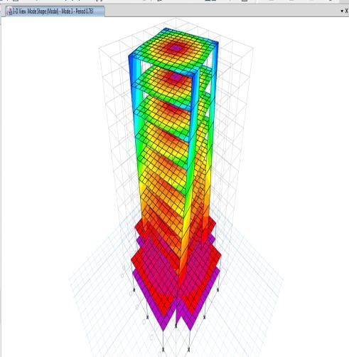

International Research Journal of Engineering and Technology (IRJET) e-ISSN: 2395-0056 Volume: 08 Issue: 12 | Dec 2021 www.irjet.net p-ISSN: 2395-0072 © 2021, IRJET | Impact Factor value: 7.529 | ISO 9001:2008 Certified Journal | Page256 Figure 17. Model 3Torsion. Figure 18. Model-4X translations. Figure 19. Model-4Torsion.

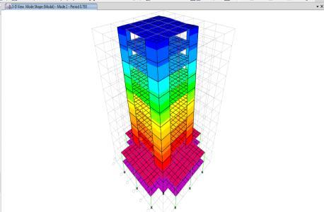

International Research Journal of Engineering and Technology (IRJET) e-ISSN: 2395-0056 Volume: 08 Issue: 12 | Dec 2021 www.irjet.net p-ISSN: 2395-0072 © 2021, IRJET | Impact Factor value: 7.529 | ISO 9001:2008 Certified Journal | Page257 Figure 20. Model 5X translations. Figure 21. Model 5Y translations.


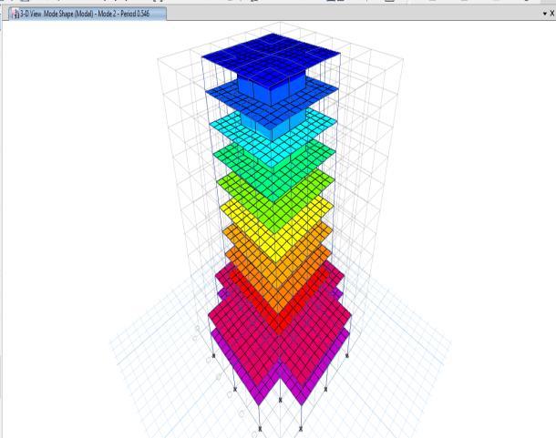
International Research Journal of Engineering and Technology (IRJET) e-ISSN: 2395-0056 Volume: 08 Issue: 12 | Dec 2021 www.irjet.net p-ISSN: 2395-0072 © 2021, IRJET | Impact Factor value: 7.529 | ISO 9001:2008 Certified Journal | Page258 Figure 22. Model 5Torsion. Figure 23. Model 5Torsion


1. Model1 exhibitedthe best amountoftimeandthelowestaverageshear,suggestingthatithasthelowest resistance relativetotheotherfiveprototypes.
Figure 24. Model 6X Torsion CONCLUSIONS
5. Fromthestoreydriftanalysis itcanbeseenthat,higherbasedimensioncanconsiderablyreducethedrift%inturn makethe structure more earthquake resistible and efficient enough in transferring the inertia forces induced due to Lateralloads.
6. All the drift values are within the permissible limits specified by IS1893 2002. Bare frame shows very flexible performance.
7. MODEL 5 and MODEL 6 are considerably showing highest base shear values among all the models, therefore, core wallsplaysavitalruletostiffenthebuildingsystemsverticallyoritmayactasverticalstiffeners.
10. From the modal mass participation investigation it can be seen that, majority of the models are showing good mass participationinfundamentalmodes,andmajorityof modelshavegot1modeshapeasXtranslation,2modeshapeas Ytranslationand3modeshapeasTorsionwhichtotallysatisfyingtherequirementsofIS 1893 2002
11. Placing shear wall is very important, in correct location of shear walls may leads to extra torsional moments, which totallyeffecttheoverallperformanceofbuildingsystems,whichcanleadtodisasterduringseismicthreatening.
9. When we add shear walls in different shapes and at different locations, they substantially decrease the fundamental timeperiodofthestructureandinturnincreasesthestiffnessandthusoveralllateralstabilitywillbeenhanced.
2. MODEL 2 and MODEL 3 reveals the same results when we compare with MODEL 1, therefore it can be stated that, orientationofshearwallswillplayamajorruleindesigningseismicresistantstructures.
International Research Journal of Engineering and Technology (IRJET) e-ISSN: 2395-0056 Volume: 08 Issue: 12 | Dec 2021 www.irjet.net p-ISSN: 2395-0072 © 2021, IRJET | Impact Factor value: 7.529 | ISO 9001:2008 Certified Journal | Page259
8. Successive openings in core walls at each floor, does not make any difference when seismic forces act on the structures.
3. ModelswithL shapesshearwallsshowsbetterresultsthananyother,thereforearrangingshearwallawayfromthe rigidcentrewillenhancethelateralstabilityofthestructureandcanconsiderablyreducetheseismichazardous.
4. When we equate the bare frame model with several other models, when we add linear or L shaped reinforced concrete wall it indicates the highest floor displacements at the top floor, thus reducing the shear wall supply substantially,reducingstoreydisplacementsandrenderingthestructurerigid.Modelswithcorewallsandcorewalls openings are showing the same results, hence it can be stated that, opening in lift elevator, doesn’t make much differenceonoverallperformanceofthebuildingsystems.

International Research Journal of Engineering and Technology (IRJET) e-ISSN: 2395-0056 Volume: 08 Issue: 12 | Dec 2021 www.irjet.net p-ISSN: 2395-0072 © 2021, IRJET | Impact Factor value: 7.529 | ISO 9001:2008 Certified Journal | Page260 REFERENCES ETABSNon linear2016 IS456:2000. IS875:1987 IS1893(Part I)2002: IS13920:1993