Key Words: Matrix Converter, vehicle to grid, Space Vector Modulation and Voltage Source Converters, Reactive Power Control
2. DESIGN AND ANALYSIS OF LINK VOLTAGE
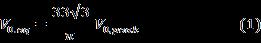
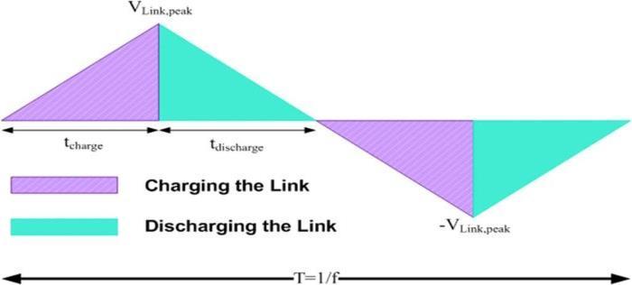
The resonating time is abandoned because it is greatly slighter than the power transfer time. In each of power cycle the discharging is indeterminate to takes place insteadoftwomodes;ittakesoneequivalentmodeinthe conversionofdc ac.Thedcsourceisusedtochargingthe link,withthisassumptionandthevirtualloaddischarged intoanequivalentvalueofoutputcurrentfortheconverter operation.Considertheaboveprogression,thevoltageacrossthe virtual load which is equivalent to the value of output voltagecanbeshownas, where V0, peak is the peak value of the ac side voltage with filtered. The equivalentoutputcurrentcanbecalculatedas wherefollows,cos(θo) and I0,peak are the peak value of the ac side powerfactorandac sidecurrent,respectively.Thecapacitor voltageincreaseslinearlywhenthelinkcapacitorchargedby thedc sidecurrentduringthechargingmode.Thecapacitor chargedlinkisdischargedintothevirtualloadduringthede energizingmode.Fig.1depictsthatthedesignprocedurecan becarriedoutbythesimplificationofonecycleofthelink voltage. Under the charging and discharging modes, the
1. INTRODUCTION
International Research Journal of Engineering and Technology (IRJET) e-ISSN: 2395-0056 Volume: 08 Issue: 12 | Dec 2021 www.irjet.net p ISSN: 2395 0072 © 2021, IRJET | Impact Factor value: 7.529 | ISO 9001:2008 Certified Journal | Page193
3PG Scholar, Dept. of Electrical and Electronics Engineering, Malla ReddyEngineering College (A), Secunderabad, Telangana, India 500100 ***
Abstract - The severe gridcurrent harmonics andripples on the DC side is induced by means of AC/DC Matrix Converter (MC). The enhanced control tactic for an AC/DC matrix converter is projected to overcome these problems, and based on an independent control proposal for the reactive andactive powers. The constant DC voltage, sinusoidal grid current and current are premeditated from the current reference generated is synthesized directly by instant analysis of power in a stationary frame. Because of reactive power control in the grid, the input power factor is approximately unity under the unbalanced conditions. The positive and negative sequences components of grid voltage are no need to extract. Hence, without a large storage requirement the planned control technique can be implemented without any difficulty. The Simulation results are obtained is to verify the efficacy of the proposedcontrol strategy.
The various emerging applications, the bidirectional components of AC/DC converter are a vital part, such as storageofenergysystems[1],thehybridAC/DCmicrogrids [2],and Vehicle to Grid(V2G) systems [3]. The voltage sourceconvertersaregenerallyused,whichhavemeritsof sinusoidal grid current, flow of power in bidirectional, capabilityoffixedDCvoltageregulationandcontrollableof powerfactor.ButtheDCvoltageshouldbelargerthanthe peakvalueofACvoltageistheintrinsicrestraintofVSCs.In generaltheDCvoltageisusuallylowerthanthepeakvalue ofACvoltageandmightbedifferentoveranextensiverange formanyapplications.Asaresult,theincreasesofcostand weight while the efficiency of the converter system is reduced by adding the bidirectional component of DC/DC converterstoequivalentthepreferredDCbusvoltagein[4], [5].Inaddition,becauseofthemassivecapacitoracrossthe DCbus,thepowerdensityandreliabilityoftheVSCsarevery poorwerepresentedin[6].Theproposedsystemhaslotsof advantages such as long life, compact design, controllable powerfactorand,sinusoidalgridcurrentwerepresentedin [7,8].Thus,theAC/DCmatrixconverterisanelegantoption to VSC based topologies for applications with slight DC voltagewerepresentedin[9,10].Alotofcontrolschemes forgridvoltagewithbalancedconditionhavebeenofferedto effectivelyoperatetheAC/DCmatrixconverterin[10] [16]. According to the range of output, the proper selection of activevectorsareneededinSpaceVectorModulation(SVM), in order to trim down the ripples in the output current describedin[10],andoptimallyutilizedbythezerovectors. The switching commutation failures and grid current distortion can be eliminated with narrow pulse by the modifiedSVMwerepresentedin[12],andpowerfactorof theinputcanbecontrolledin[13].Theswitchinglossescan be minimized techniques were presented in [14, 15]. The input currentandoutputcurrentseffectivelyregulatedbyprognosticcontrolmethodwasintroducedin[16].
Performance Improvement of AC/DC MatrixConverter with Unbalanced Grid Voltage N. Rajeswaran1, P. Marimuthu2 and Ilapuram Mahesh3 1, 2Professor,Dept. of Electrical and Electronics Engineering, Malla Reddy Engineering College(A), Secunderabad, Telangana, India 500100


3. IMPLEMENTATION OF PROPOSED TECHNIQUE
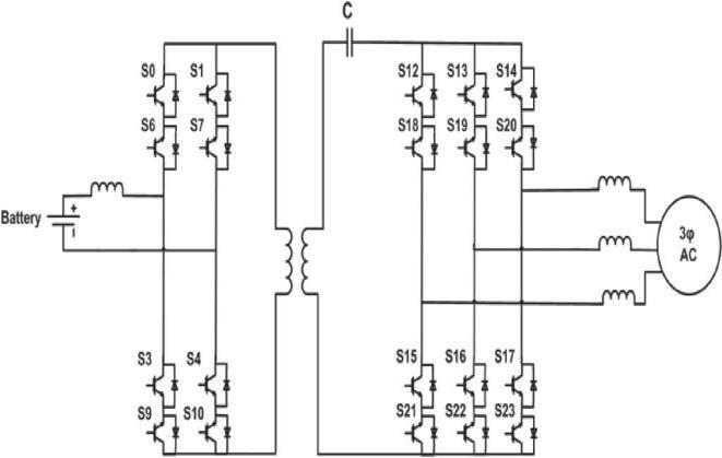
Fig 2: InverterwithGalvanicIsolationMethod
By adding up the link with a single phase transformer withhigh frequencybyprovidedthegalvanicisolationfrom the series ac link inverter. The transformer leakage inductancemayplaythevitalroleofthelinkinductance.Fig. 2 depicts the proposed method of inverter with galvanic isolation.Thelinkcapacitorischargedduringthesideofacand discharged into the sideof dc for the period of the three phaseac dcconversionprocess.Inthismodeofoperation have the two modes for charging and it is analogous to the conversion of
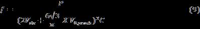
The average value of the voltage at dc side can be calculatedas where T is thetimeperiodofthevoltageatthe link.From the Eqn. (5) and (6), thepeaklinkvoltageasfollows, Atanyoperatingpointstheaveragevalueofthevoltage at dc side and the amplitude of the ac side voltage are approximatelyconstant,thenthepeakvoltageatlinkwillbe nearlystableoverarangeofpower.Thefrequency(f)ofthe link can be selected depends upon the switching characteristics and the system power rating. The link capacitance determined based upon the value of the link frequencyisselectedasfollows, Fromtheequation,thevalueoflinkcapacitorissmaller can be achieved by selecting the link frequency as higher value.Theresonatingperiodsatfullpowercanbeminimized byselectingthepropervalueoflinkinductance.TheEqn.(8) canberewrittenas,
International Research Journal of Engineering and Technology (IRJET) e-ISSN: 2395-0056 Volume: 08 Issue: 12 | Dec 2021 www.irjet.net p ISSN: 2395 0072 © 2021, IRJET | Impact Factor value: 7.529 | ISO 9001:2008 Certified Journal | Page194 behavior of the circuit can be described based on the followingequations, Intheaforementionedequations,VLink,peak,Idc,tdischargeand tcharge beasymbolofthepeaklinkvoltageofthecapacitor, averagecurrentinthedc side,totalde energizingtimeand entire energizing time during mode 1 respectively. The relationshipbetweenthedischargingandchargingtimecan befoundfromtheEqn.(3)and(4).
Fig -1:Seriesac linkInverterwithonecycleofthelink voltage
Theinverterproposedfortheperformanceimprovementas in Fig. 2, and thisisanexpansionmodelofthedc dcCUK converter. The link capacitor will be charged through the sideofdcandthenthecapacitordischargedintothesideof acduringthedc acconversionprocessandtheonlyonelink tobedischargedbuttherearethreephasesatthesideofac. The discharging mode will be divided into two modes by involving all three phases for lowering total harmonic distortions(THDs).Thelinkcapacitorwillbechargedagain fromtheinputandthendischargedintotheoutputphases duringthesecondhalfcycle;butdischargedandchargedin reversepathwaybythelinkcapacitor.


International Research Journal of Engineering and Technology (IRJET) e-ISSN: 2395-0056 Volume: 08 Issue: 12 | Dec 2021 www.irjet.net p ISSN: 2395 0072 © 2021, IRJET | Impact Factor value: 7.529 | ISO 9001:2008 Certified Journal | Page195
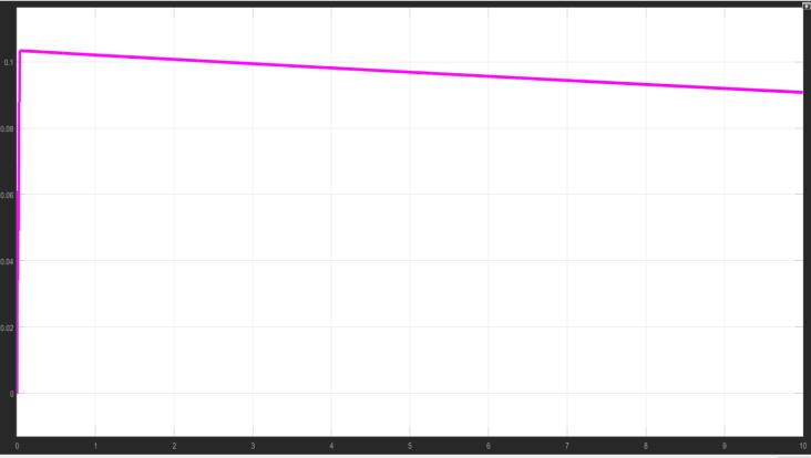
Thesimulationresultscorrespondingtoadc acconverter usingtheproposedconverterisoffered.TheSimulationis carried out using MATLAB. The load used for the simulationis200 Wsystemandinputsidefilterof1 mH isused.Theinductoris only used to form the filter is and the harmonics are not completely attenuated and thiscanbecompletelyattenuatedwith LCLfilter.Fig.9 showstheoutputcurrent.The2mHofinductorseachis used for output filter. The LC filter can be preferred to decrease the THD and total harmonics. The LC filter formedbyacapacitorof10μFisattachedacrosstheeach loadandalsotheneutralpoint.Fig.9showsthecurrentat load,whichhasaverylowTHDandverysmooth.
Fig 3: Voltage,CurrentoftheLinkandline to line voltages(unfiltered)duringthepowerconversionofdc ac Fig. 3 represents the behavior of the converter circuit throughout each mode and during the operation it is understandable that the phase pairs carrying the continuouslymaximuminstantaneousvalueofvoltage.The time span is shown in Fig.3, it is understood that, the completevalueofthecurrentinphaseAislargerthanthe phaseBattheacside.Fig.3depictsthatthecorresponding waveforms of ac dc conversion. The determination of switchingschemeisdesiredforsimplifyingtheswitchingof the converters. The switches for the mode of each power transferringofconductionandduringtheresonatingmode areidentifiedbased on zero currentturnoffandsoftturn onandminimumnumberofswitchingaswellaspossiblein eachFig.cycle.4represents the behavior of the ac dc converter circuitthroughouteachmode.Thepolarityofthecurrentin thelinkandvoltagewilldecidedtheswitchesthataccomplish ineachpowertransfermode.Forexample,duringmode1 operationthevoltageandcurrentatthelinkarepositivein dc ac converter system. The modes of main switches conducting will be based upon the line to line reference voltageandalongsidewiththepolaritiesofthelinkcurrent andvoltage.
Fig - 4: Voltage,CurrentoftheLinkandline to line voltages(unfiltered)duringthePowerConversionofac dc 4. SIMULATION RESULTS AND DISCUSSIONS
dc ac, the both the directions of positive and negative are chargedanddischargedbythelink,andalsoinbetweeneach power transfer mode a resonating mode occurs. The conversionoccursinboththedirections,thelinkcyclehas the12modesofoperationanditconsistsofsixresonating modes andsixpowertransfermodes.Theminimizationof switching command is the significant setback during the converter operation. The incoming switches are tuned in advance oftimeaccordingto thatthe scheme ofswitching wasdevelopedfortheconverteroperations
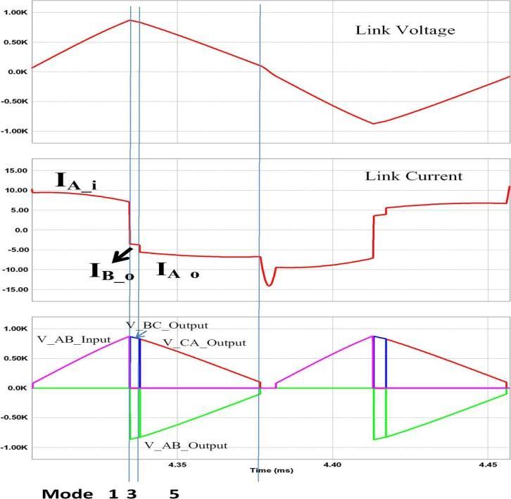
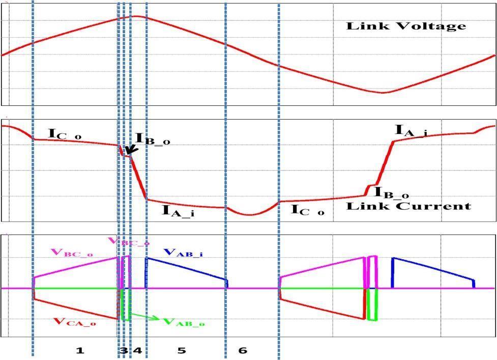
Fig OutputCurrent CONCLUSION
5.
Thecontrolstrategypresentedisanefficientforan matrix converter of AC/DC grid voltage under the unbalanced condition to achieve sinusoidal grid current, constantvoltage at output, and close to unity input power factor. The proposed control strategy provides a self regulating control proposal for the active and reactive. By analyzingtheinstantaneouspowerinastationaryframe,the inputcurrentreferencewasgeneratedsinusoidallyinspiteof thegridvoltageunderunbalancedcondition.Asaresult,the projected technique effortlessly obtains sinusoidal grid current is synthesized directly with the reference of input current. In addition, the power factor of input becomes nearlyunitybyadjustingthereactivepoweratthegridcan bezeroaveragevalue.Theimplementedtechniquedoesnot requiredremovalofthecomponentsofgridvoltagesequence ortheinputcurrentcontroller.Subsequentlytheproposed schemeofcontrolcanbeimplementedsimplywithoutbulky storage.Theefficacyofthecontrolstrategyimplementedwas confirmedbysimulationresults.
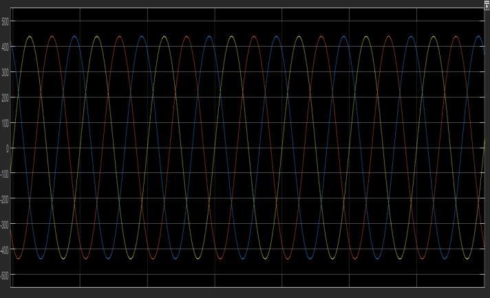
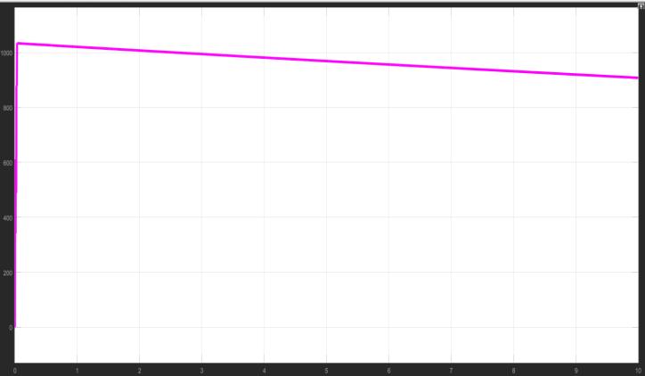
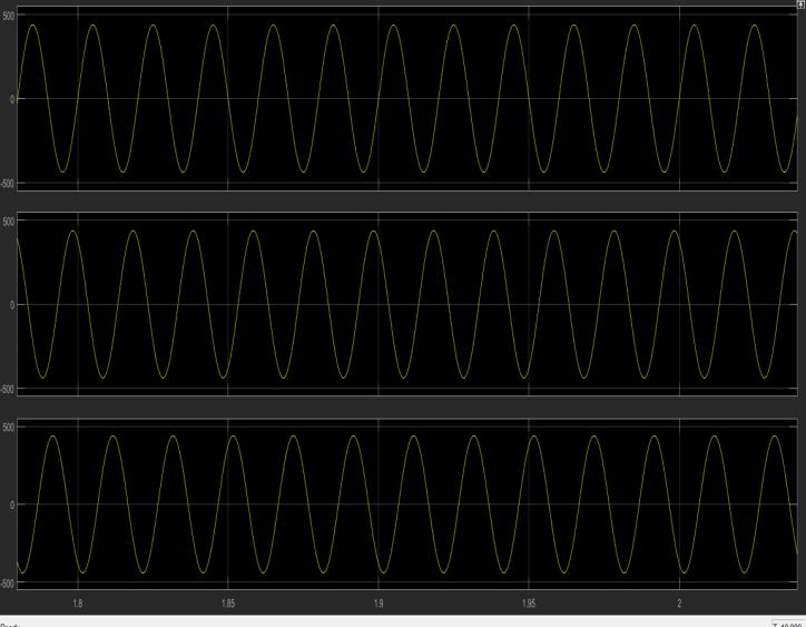
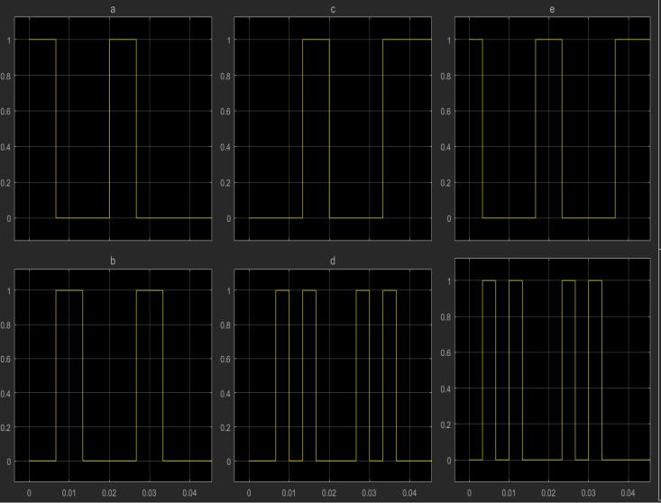
International Research Journal of Engineering and Technology (IRJET) e-ISSN: 2395-0056 Volume: 08 Issue: 12 | Dec 2021 www.irjet.net p ISSN: 2395 0072 © 2021, IRJET | Impact Factor value: 7.529 | ISO 9001:2008 Certified Journal | Page196 Fig - 5: GridSideVoltage Fig 6: GridSidePhasetoPhaseVoltage Fig - 7: GatePulses Fig 8: OutputVoltage
9:
[13] K.You,D.Xiao,M.F.Rahman,andM.N.Uddin,“Applying Reduced General Direct Space Vector Modulation ApproachofAC ACMatrixConverterTheorytoAchieve Direct Power Factor Controlled ThreePhase AC DC MatrixRectifier,”IEEETrans.Ind.Appl.,vol.50, no.3, pp.2243 2257,May2014.
[10] M. Su, H. Wang, Y. Sun, J. Yang, W. Xiong, and Y. Liu, “AC/DCMatrixConverterWithanOptimizedModulation Strategy for V2G Applications,” IEEE Trans. Power Electron.,vol.28,no.12,pp.5736 5745,Dec.2013.
REFERENCES
[1] M. P. Akter, S. Mekhilef, N. M. L. Tan, and H. Akagi, “Modified Model Predictive Control of a Bidirectional AC DC Converter Based on Lyapunov Function for EnergyStorageSystems,”IEEETrans.Ind.Electron.,vol. 63,no.2,pp.704 715,Feb.2016.
[5] N. M. L. Tan, T. Abe, and H. Akagi, “Design and Performance of a Bidirectional Isolated DC DC ConverterforaBatteryEnergy StorageSystem,”IEEE Trans. PowerElectron., vol. 27, no. 3, pp. 1237 1248, Mar.2012.
[12] S. Liu, Xiao; Zhang, Qingfan; Hou, Dianli; Wang, “ImprovedSpaceVectorModulationStrategyforAC DC MatrixConverters,”J.PowerElectron.,vol.13,no.4,pp. 647 655,2013.
International Research Journal of Engineering and Technology (IRJET) e-ISSN: 2395-0056 Volume: 08 Issue: 12 | Dec 2021 www.irjet.net p ISSN: 2395 0072 © 2021, IRJET | Impact Factor value: 7.529 | ISO 9001:2008 Certified Journal | Page197 APPENDIX: ParametersoftheSeriesAClinkinverter: a) 5KWSystem: Vdc=200V, Vac_II_rms = 208V, Link Inductance = 100µH, Link Capacitance =0.4µF
[14] M. Mengoni, L. Zarri, A. Tani, G. Rini, G. Serra, and D. Casadei,“Modulationstrategywithminimumswitching losses for three phase AC DC matrix converters,” in 201416thEuropeanConferenceonPowerElectronics andApplications,2014,pp.1 10.
[15] M.Mengoni,L.Zarri,A.Tani,G.Rizzoli,G.Serra,andD. Casadei,“Modulationstrategiesforthree phaseAC DC matrixconverters:Acomparison,”in2016IEEEEnergy ConversionCongressandExposition(ECCE),2016,pp. 1 7.
[16] B.FengandH.Lin,“FiniteControlSetModelPredictive ControlofAC/DCMatrixConverterforGrid Connected BatteryEnergyStorageApplication,”J.PowerElectron., vol.15,no.4,pp.1006 1017,2015.
[4] M. Yilmaz and P. T. Krein, “Review of Battery Charger Topologies,ChargingPower Levels,andInfrastructure for Plug In Electric and Hybrid Vehicles,” IEEE Trans. Power Electron., vol. 28, no. 5, pp. 2151 2169, May 2013.
[11] B.Feng,H.Lin,andX.Wang,“Modulationandcontrolof ac/dc matrix converter for battery energy storage application,”IETPowerElectron.,vol.8,no.9,pp.1583 1594,2015.
[6] M. A. Sayed, K. Suzuki, T. Takeshita, and W. Kitagawa, “PWM Switching Technique for Three Phase BidirectionalGrid TieDC AC ACConverterWithHigh FrequencyIsolation,”IEEETrans.PowerElectron.,vol. 33,no.1,pp.845 858,Jan.2018.
[9] G.Rizzolietal.,“ComparisonbetweenanAC DCmatrix converter and an interleaved DC dc converter with powerfactorcorrectorforplug inelectricvehicles,”in 2014 IEEE International Electric Vehicle Conference (IEVC),2014,pp.1 6.
b) 200WSystem: Vdc=70V,Vac_II_rms=50V,LinkInductance=100µH,Link Capacitance=0.4µF
[3] G.Buja,M.Bertoluzzo,andC.Fontana,“ReactivePower Compensation Capabilities of V2G Enabled Electric Vehicles,”IEEETrans.PowerElectron.,vol.32,no.12,pp. 9447 9459,Dec.2017.
[7] D.Varajão,R.E.Araújo,L.M.Miranda,andJ.A.P.Lopes, “Modulation Strategy for a Single Stage Bidirectional and Isolated AC DC Matrix Converter for Energy StorageSystems,”IEEETrans.Ind.Electron.,vol.65,no. 4,pp.3458 3468,Apr.2018.
[2] P. Yang, Y. Xia, M. Yu, W. Wei, and Y. Peng, “A DecentralizedCoordinationControlMethodforParallel Bidirectional Power Converters in a Hybrid AC DC Microgrid,”IEEETrans.Ind.Electron.,vol.65,no.8,pp. 6217 6228,Aug.2018.
[8] H.N.NguyenandH.H.Lee,“AnEffectiveSVMMethod for Matrix Converters With a Superior Output Performance,”IEEETrans.Ind.Electron.,vol.65,no.9, pp.6948 6958,Sep.2018.