2. LITERATURE REVIEW
International Research Journal of Engineering and Technology (IRJET) e ISSN: 2395 0056 Volume: 08 Issue: 12 | Dec 2021 www.irjet.net p ISSN: 2395 0072 © 2021, IRJET | Impact Factor value: 7.529 | ISO 9001:2008 Certified Journal | Page1654 A COMPARATIVE STUDY ON WIND ANALYSIS OF TAPERED AND NONTAPERED REINFORCED CONCRETE CHIMNEY Swathi Lankadasari1 , Pradeep Uppula2 , Ruddhida Vidwans3, Mohan Krishna Gurugubelli4 1Independent Researcher, Srikrishna Saiesha Legend, Nizampet, Hyderabad, Telangana, India 2B Tech, Department of Civil Engineering, Malla Reddy Institute of Technology, Secunderabad, Telangana, India 3PhD Student, Jain (Deemed to be University), Bangalore, Karnataka, India 4Senior Design Engineer, Ramboll India Pvt Ltd, Hyderabad, Telangana, India *** Abstract Rapid industrialization due to globalization results in the raise of tall chimneys around the world. Considering the structural variations in chimney design, the present paper discusses the analysis of reinforced concrete chimneys by considering two chimney sections i.e., Tapered & Non Tapered. The main focus is to study the wind analysis considering along wind loads with two different sections of chimneys. In the typical case of slender, tapered Reinforced Concrete Chimneys, it is the along wind response that 1987intensityproposedgenerallypredominatesandgovernsthedesign.ThestructuresinthisworkwereanalyzedusingthesamewindwhichwasobtainedaccordingtoIS:875(Part3)andthewindloadsonchimneywerecalculated according to ‘CRITERIA FOR DESIGN OF REINFORCED CONCRETE CHIMNEY’ i.e., IS: 4998 1992 chimney (part 1). The chimney structures were developed using commercial loads.chimneytheindustrialloadssoftwareSTAAD.ProV8iandtheeffectoflateralloadi.e.,windareanalyzed.GiventherapiddevelopmentinthesectorandconsiderationofGroundLevelPollution,studydrawsitsimportancebydesigninganefficientusingSTAAD.ProV8isoftwarewithrespecttowind Key Words: Chimneys, STAAD.Pro, wind loads, Industries, pollution.
INTRODUCTION
1.
Aslarge scaleindustrialdevelopmentsaretakingplace allaround,anoverwhelmingnumberoftallchimneyswould be required to be constructed every year. The primary function of a chimney is to discharge pollutants into the atmosphereathigher elevationsandvelocitiessothatthe concentrationofpollutantsdeemedharmfulwereavoidedin the human vicinity. The control standards have led to the construction of increasingly tall reinforced concrete (RC) chimneysworldwide.Constructionoftallchimneysneedsa better understanding of loads acting on them and of the structural behavior, so that with the help of modern construction equipment and techniques, the most favored materialforchimneyconstruction,couldbeusedefficiently [1].The properdesignand constructionofsuchchimneys willcreateself standingstructurestoresistwindloadand otherforcesactingonthem.
Aliteraturereviewiscarriedoutontheanalysisofchimneys with a special interest in the effect of wind loads on the chimney. Vickery and Basu proposed an empirical model whichiswidelyrecognizedandacceptedasamodelforthe predictionofacross windresponseonatallcircularchimney andithasbeenrecommendedinafewinternationalCodesof Practice[2].Asalientfeatureofthismodelistheconceptof negativeaero dynamicdamping,usingwhichtheenhanced response due to vortex shedding in the lock in region is computed.Whilethismightbeausefulconcept,Zhouet.al. (2000) reported that this assumption oversimplifies the correlation of the across wind forces along the height [3]. Chmielewski,et.al.(2005)studiednaturalfrequenciesand naturalmodesofhighmulti flueindustrialRCchimneyswith theflexibilityofsoil[4].Thispaperusedthefiniteelement methodforanalysis.Also,experimentalworktoinvestigate the free vibration response is carried out by using two geophonesensorsandexperimental resultsarecompared with analytical results. The results show that the soil flexibilityunderthefoundationinfluencesthenaturalmodes and natural periods of the chimney by a considerable margin.Davenportdevisedthegustfactormethod,andthis method has been widely used for along wind calculation during the past three decades [5]. Following Davenport's formulation, several researchers suggested various modifications to the gust factor method [6]. Flaga and Lipecki (2010) analyzed the lateral response on concrete chimneysofcircularcross sectionsduetovortexexcitation. A mathematical model of vortex shedding is proposed for calculatingthemaximumdisplacementofthechimneyatthe topduetovortexshedding[7].Researchersalsoconducted severalstudiestodeterminethewind inducedvibrationofa full scalechimney.Windtunneltestinghasprovedtobean efficient and practical approach towards the study of the response of tall structures, particularly chimney models, underatmosphericwindflow[8].KareemandHseih(1986) carried out the reliability analysis of concrete chimneys under wind loading [9]. In this paper, safety criteria are takenintoconsideration.Excessivedeflectionatthetopof the chimney and exceedance of the ultimate moment capacityofthechimneycross sectionatanylevelweretaken as failure criteria. The formulation for wind induced load effects, in both along wind and across wind directions, is

K1 = Probabilityfactor(Riskcoefficient).Fromtable1 K1 = 1.08(Forimportantbuilding&Powerplant
International Research Journal of Engineering and Technology (IRJET) e ISSN: 2395 0056 Volume: 08 Issue: 12 | Dec 2021 www.irjet.net p ISSN: 2395 0072 © 2021, IRJET | Impact Factor value: 7.529 | ISO 9001:2008 Certified Journal | Page1655 presentedaccordingtotheprobabilisticstructuraldynamics. Few researchers also highlighted the masonry type of construction without any experimental investigation. It is therefore appropriate herein to study these constructions since existing knowledge regarding their behavior is very limitedand,inaddition,inmanyplaces,thesechimneysare considered the silent witnesses of the past, and they are protectedbylawasculturalheritage.Thefirstworkanalyses the typology and structure of industrial chimneys built between1870andthefirstdecadesofthe20thcenturyin theItalianregionsof‘Piedmont’and‘Veneto’.Thestudyalso analyses problems associated with their restoration. The second paper studies the behavior of three significant chimneys in these areas using the finite element method withlinearanalysis,takingintoaccounttheself weight of the chimney, wind, temperature differences, and earthquakesasactingforces.Pistoneetal.(1996)dealwith restoration problems in masonry chimneys. Recently, two moreexamplesaddressingthistypeofconstructionare(a) Pallare´s et al. (2004), where different failure criteria are comparedto studythefailure ofa masonry chimney[10], and(b)Vanetal,(2004),inwhichstabilityandpreservation ofthesechimneysaretreated[11].TamuraandNishimura (1990)studiedthe elasticmodel oftheRCchimneyinthe windtunnelandconfirmedthatepoxyresinmaterialcanbe used to simulate the dynamic behavior of the reinforced concretechimneyinwindtunneltesting[12].Theliterature review presented above shows that there are several published worksonconcretechimneys.Experimental and theoretical studies are presented on the behavior of tall chimneyssubjectedtowind.Itisfoundthatthemajorityof theresearchpapersonthechimneyareconcentratedonits responsetowindandearthquakeanalysis.Forthepresent study,weconsiderpapersonwindeffectsonchimneys.The structures proposed in our work were analyzed using the samewindintensitywhichwasobtainedaccordingtoIS:875 (Part 3) 1987 [13] and the wind loads on chimney were calculated according to ‘CRITERIA FOR DESIGN OF REINFORCED CONCRETE CHIMNEY’ i.e., IS: 4998 1992 chimney(part 1)[14]. 3. METHODOLOGY WIND LOAD CALCULATIONS ON CHIMNEYS AS PER IS: 4998-1992 (PART 1) Designwindpressure,PZ =0.6VZ2 (clause5.4,IS875 part 3 Design1987)windspeed,Vz=Vb.K1.K2.K3 (clause5.3,IS875 part 3 1987) Basicwindspeedfromfig.1pageno.9ofIS875 part.3 1987,clause5.2 AsVb =50m/s(Basicwindspeedinvizag)
K2structures)=Terrainheightandstructuresizefactor K2 = 1.1(For50mheightandcategory2,classC) K3 = 1.0 VZ = 50x1.08x1.1x1.0 VZ = 59.4m/s Windvelocityatdesiredheightisgivenby VZ =59.4x(Z/10)0.2 AccordingtoIS4998 1992PartI,thedragforceoralong windloadperunitheightofthechimneybypeakfactor method(or)simplifiedmethodisgivenby FZ =PZ Cd dZ Where PZ =Designwindpressure(fromIS875 Part3) Cd =0.8(CoefficientofdragasperIS4998 1992 Part1)dZ =DiameteratheightZ Thevelocities,pressuresandrespectiveforceswere calculatedandtabulatedbelow: NoS. (Z)Height (drDiamete Z) (VVelocity Z) (PPressure Z) (FForce Z) 1 5 4.8 51.71 1.604 6.161 2 10 4.6 59.40 2.117 7.791 3 15 4.4 64.42 2.490 8.764 4 20 4.2 68.23 2.793 9.386 5 25 4.0 71.35 3.054 9.774 6 30 3.8 74.00 3.285 9.987 7 35 3.6 76.31 3.494 10.063 8 40 3.4 78.38 3.686 10.026 9 45 3.2 80.25 3.864 9.891 10 50 3.0 81.96 4.030 9.672 Table 1: CalculationofwindforceatbasicwindspeedVb =50m/s(Tapered) NoS. (Z)Height (dDiameter Z) (VVelocity Z) (PPressure Z) (FForce Z) 1 5 5 51.71 1.604 6.418 2 10 5 59.4 2.117 8.468 3 15 5 64.42 2.49 9.959 4 20 5 68.23 2.793 11.174 5 25 5 71.35 3.054 12.217 6 30 5 74.00 3.285 13.141 7 35 5 76.31 3.494 13.977 8 40 5 78.38 3.686 14.74 9 45 5 80.25 3.864 15.45
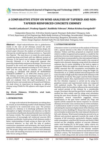
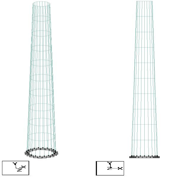
International Research Journal of Engineering and Technology (IRJET) e ISSN: 2395 0056 Volume: 08 Issue: 12 | Dec 2021 www.irjet.net p ISSN: 2395 0072 © 2021, IRJET | Impact Factor value: 7.529 | ISO 9001:2008 Certified Journal | Page1656 5 10 50 5 81.96 4.03 16.12 Table 2: CalculationofwindforceatbasicwindspeedVb = 50m/s(Non Tapered) Software used STAAD.PRO V8i World's No. 1 Structural Analysis and Design Software SupportingIndianandmajorInternationalcodes.STAADor (STAAD.Pro) is astructural analysisand design computer program originally developed by Research Engineers InternationalinYorbaLinda,CA. 4. RESULTS AND DISCUSSIONS ThechapterpresentsthemodelsdevelopedinStaad.proV8i, introduction to the software, loading on the chimney structures,classificationofchimney,analysisresults,nodal displacements,stresses,stresscontoursetc.indetail. The images below show the structure of an industrial chimney in isometric view and in front view which was modeledinSTAAD.Prov8i. MODEL FOR ANALYSIS OF RC CHIMNEY TAPERED RC CHIMNEY Fig 1: Model of Tapered RC Chimney in Staad.pro V8i NON-TAPERED RC CHIMNEY Fig -2: Model of Non-Tapered RC Chimney in Staad.pro V8i TheimagesbelowrepresentthewindloadontheTapered& Non Taperedchimneyconsideredinonedirection. WIND LOADING ON THE CHIMNEY STRUCTURE Fig 3: Loading view of the chimney structure.

International Research Journal of Engineering and Technology (IRJET) e ISSN: 2395 0056 Volume: 08 Issue: 12 | Dec 2021 www.irjet.net p ISSN: 2395 0072 © 2021, IRJET | Impact Factor value: 7.529 | ISO 9001:2008 Certified Journal | Page1657
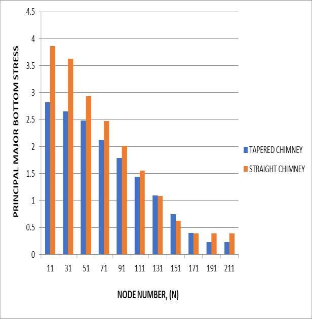
The graphs showed a clear vision that the stresses were more in the Straight RC Chimney than the Tapered RC Chimneyattheparticularnode.Itwasclearfromthegraphs Compression Side- Asthechimneystructureissymmetrical
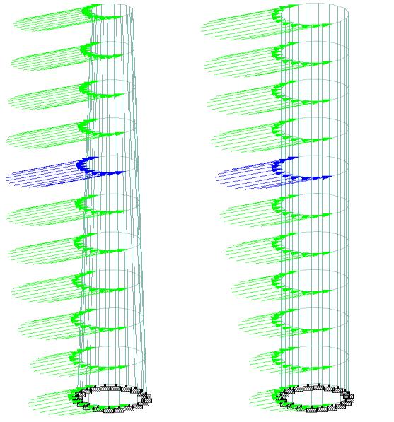
Summary of Graphs (Nodal displacements)
TheabovegraphsrepresenttheNodaldisplacementson1) Thetensionsideand2)Thecompressionside.Thegraphs wereplottedatevery5mheightofthechimneystructures withrespectivenodesofthesides.
Graphs Tapered & Non Tapered RC
Fig -6: Principal Major Top Stress on Tension Side
Tension Side or Windward side Intheabovegraphs,the displacements are plotted for Tapered & Straight RC Chimneyforthesamewindintensity.Bothchimneysections werementionedattherightofthesection.TheStraightRC ChimneyhadthegreaterdisplacementovertheTaperedRC Chimney, at the particular node. Maximum displacement occursatthetopofthestructurebothinTapered&Straight Chimneys.Thedisplacementsatthebottomofthestructure arezero,asthestructureissupportedoraffixedbyafixed support.Itwasclearthatforboththechimneysections,the maximumdisplacementoccursinthetensionzoneonly.The graphs clearly showing that the displacement at every comparative node of Straight RC chimney had a greater displacementthanthatofTaperedRCchimney.Hereitwas observedthattheheightofthechimneystructureisdirectly proportional to the displacements. As the height of the structure increases, the value of the displacements also aboutincreases.itsverticalaxis,thevariationofthedisplacementson thecompressionsidetothetensionsideisveryless.From the graphs also it is clear that, a very less difference in displacement occurs on compression side to that of the tensionside,butthemaximumdisplacementdidn’toccurin compressionzone
Graphs for Principal Major Top & Bottom Stresses of Tapered & Non Tapered Chimneys
Fig -7: Principal Major Bottom Stress on Tension Side
Fig 4: Nodal displacements on Tension side Fig -5: Nodal displacements on Compression side
for
Chimneys
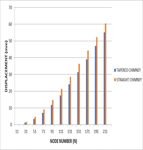
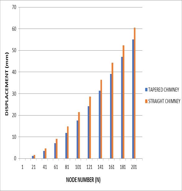
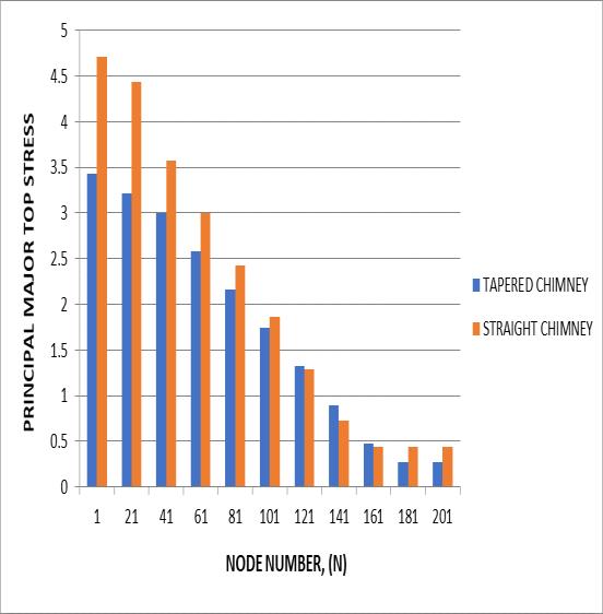
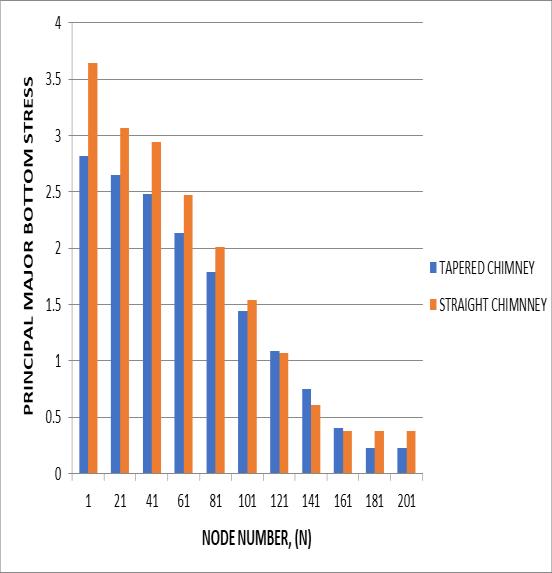
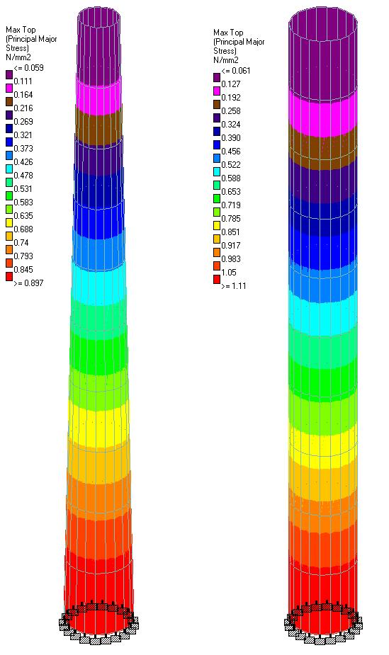
Fig 10: Stress Contours due to self weight of chimneys Stress Contours due to Wind load on the chimeys
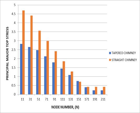
Fromthegraphsitisclearthatthestress behavioronthe compressionsideisalmosthavingthesamebehaviorasthat onthetensionside.
International Research Journal of Engineering and Technology (IRJET) e ISSN: 2395 0056 Volume: 08 Issue: 12 | Dec 2021 www.irjet.net p ISSN: 2395 0072 © 2021, IRJET | Impact Factor value: 7.529 | ISO 9001:2008 Certified Journal | Page1658
that the stresses vary linearly along the structure. Here it was observed that the height of the chimney structure is inverselyproportionaltothePrincipalMajorTop&Principal Major Bottom stresses. As the height of the structure increases,thevalueofthestressesdecreases. Thenit was clear that the maximum stresses occur at the base of the chimneystructure.Hencethestressesaremaximumatthe base,andminimumatthetopofthechimneystructure.
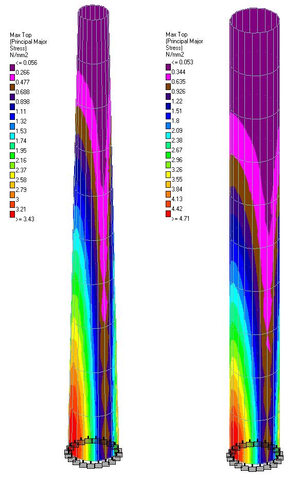
Fig 11: Stress Contours due to wind load on chimneys
Fig -9: Principal Major Bottom Stress on Compression Side
Thefollowingimagesi.e.,Fig10and11representstheactual stressbehaviorfortheloadingcondition(eitherself weight orwindload)givenonthechimney.Eachcolordefinesthe unique stress range which helps to know the structural behavior of the chimney under specific loading condition.Theactualstressestobelimitedwithinallowable stresses to ensure the structure safety. The end value (bottom)intheaboveimagesignifiescriticalstresses.
Stress Contours due to self weight of the chimeys
Fig 8: Principal Major Top Stress on Compression Side
GalemannT,RuscheweyhH,“Measurementsofwind inducedvibrationsofafull scalesteelchimney,”Journalof WindEngineeringandIndustrialAerodynamics,vol.41,Oct. 1992, pp. 241 252, doi: https://doi.org/10.1016/0167 6105(92)90416 [9] KareemA,HseihJ,“Reliabilityanalysisofconcrete chimneysunderwindloading,”JournalofWindEngineering andIndustrialAerodynamics,vol.25,Jan.1986,pp.93 112, doi:https://doi.org/10.1016/0167 6105(86)90106 [10] PallarésFJ,AgüeroA,MartínM,“Seismicbehaviour of industrial masonry chimneys,” International Journal of SolidsandStructures,vol.43,Apr.2006,pp.2076 2090,doi: [11]https://doi.org/10.1016/j.ijsolstr.2005.06.014
International Research Journal of Engineering and Technology (IRJET) e ISSN: 2395 0056 Volume: 08 Issue: 12 | Dec 2021 www.irjet.net p ISSN: 2395 0072 © 2021, IRJET | Impact Factor value: 7.529 | ISO 9001:2008 Certified Journal | Page1659 TheabovefigurerepresentsthestresscontourofTapered chimney&Non TaperedChimneyduetowindloadonthe structure. 6. CONCLUSION
VanZijlGP,DeVriesPA,VermeltfoortAT,“Masonry walldamagebyrestrainttoshrinkage,”JournalofStructural Engineering, vol. 130, Jul. 2004, pp. 1075 1086, doi: [12]9445(2004)130:7(1075)https://doi.org/10.1061/(ASCE)0733
[4] ChmielewskiT,GórskiP,BeirowB,KretzschmarJ, “Theoretical and experimental free vibrations of tall industrial chimney with flexibility of soil,” Engineering Structures, vol. 27, Jan. 2005, pp. 25 34, doi: [5]https://doi.org/10.1016/j.engstruct.2004.08.009
6
ACKNOWLEDGEMENT
8
TheauthorsacknowledgeDrManendraBabu Lankadasari fromMemorialSloanKetteringCancerCenter,NewYorkfor hisvaluableinputs. Baghel S, Vyas JN, “Literature Survey on ComparativeanalysisofRC&SteelChimney,”International ResearchJournalofEngineeringandTechnology,vol.6,Jul. 2019,pp.44 47,doi:IRJET V6I70820190830 66894 b2r5vt with cover page v2.pdf
DavenportAG,SparlingBF,“Dynamicgustresponse factorsforguyedtowers,”JournalofWindEngineeringand IndustrialAerodynamics,vol.43,Jan.1992,pp.2237 2248, doi:https://doi.org/10.1016/0167 6105(92)90662 T
[7] Flaga A, Lipecki T, “Code approaches to vortex sheddingandownmodel,”Engineeringstructures,vol.32, Jun. 2010, pp. 1530 1536, doi: [8]https://doi.org/10.1016/j.engstruct.2010.02.001
[2] Vickery BJ, Basu R, “Simplified approaches to the evaluationoftheacross windresponseofchimneys,”Journal ofWindEngineeringandIndustrialAerodynamics,vol.14, Dec.1983,pp.153 166,doi:https://doi.org/10.1016/0167 6105(83)90019 3
[3] ZhouY,KareemA,GuM,“Equivalentstaticbuffeting loadsonstructures,”JournalofStructuralEngineering,vol. 126, Aug. 2000, pp. 989 992, doi: 9445(2000)126:8(989)https://doi.org/10.1061/(ASCE)0733
Maximumdisplacementoccursatthetopofthestructure, whereasthedisplacementsatthebottomofthestructureare zero, as the structure is supported or affixed by a fixed support.Hereitisobservedthattheheightofthechimney structureisdirectlyproportional tothedisplacements. As the height of the structure increases, the value of the displacementsalsoincreases.Incrementalinwindintensity leadstotheincrementofthedisplacementinthatdirection. Asthestructureofchimneyisfixedatitsbottom,itactslike acantileverbeam,andthemaximumdisplacementoccurred atthepeakofthestructure.ItwasobservedthatTheNon TaperedRCChimneyhadthegreaterdisplacementoverthe Tapered RC Chimney, at the particular node. And the maximum displacement occurs in the tension zone only, whereas the compression zone displacements are utmost similar to that of tension side due to symmetry of the structure.Hereitisobservedthattheheightofthechimney structure is inversely proportional to the Principal Major Top&PrincipalMajorBottomstresses.Astheheightofthe structure increases, the value of the stresses decreases. It was observed that the stresses developed in the chimney structure are maximum at the base of the structure and minimumatthetopofthestructure.Itwasobservedthatthe stresses were high in Non Tapered RC chimney than the TaperedRCchimney.
DavenportAG,“Gustloadingfactors,”Journalofthe Structural Division, vol. 93, Jun. 1967, pp. 11 34, doi: [6]https://doi.org/10.1061/JSDEAG.0001692
TamuraY,NishimuraI,“Elasticmodelofreinforced concretechimneyforwindtunneltesting,”JournalofWind EngineeringandIndustrialAerodynamics,vol.33,Mar.1990, pp. 231 236, doi: https://doi.org/10.1016/0167 6105(90)90038 E [13] IS: 875(Part III):1987 Code of practice for design loadsforbuildingsandstructures,publishedbyBureauof Indianstandards. [14] IS: 4998(Part I):1992 Criteria for design of Reinforced concrete Chimneys, published by Bureau of Indianstandards.
REFERENCES [1]