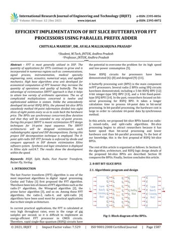
2. 8 BIT BIT SLICE BPUS 2.1. Algorithmic program and design Fig 1: Block diagram of the BPUs.
International Research Journal of Engineering and Technology (IRJET) e ISSN: 2395 0056 Volume: 08 Issue: 12 | Dec 2021 www.irjet.net p ISSN: 2395 0072 © 2021, IRJET | Impact Factor value: 7.529 | ISO 9001:2008 Certified Journal | Page1587 EFFICIENT IMPLEMENTATION OF BIT SLICE BUTTERFLYFOR FFT PROCESSORS USING PARALLEL PREFIX ADDER CHITYALA MAHESH1 , DR. AVALA MALLIKARJUNA PRASAD2 1Student, M.Tech, JNTUK, Andhra Pradesh 2Professor, JNTUK, Andhra Pradesh *** Abstract FFT is most generally utilized in DSP. The quantity of applications for FFTs continues to grow and is incorporated in numerous regions such as:communications, signal process, instrumentation, medical specialty engineering, sonic, acoustics, numerical ways, and applied mechanics. High base algorithms area unit developed for economical computation of FFT however they increase the quantity of operations and quality of butterfly. The key advantage of victimization SRFFT approach is that it helps to attain low variety of arithmetic operations. The no of complicated multiplications concerned is twelve and sophisticated addition is sixteen. Unlike the antecedently developed bit serial RSFQ BPUs, the planned bit slice BPUs ceaselessly method 64 point information divided into eight slices of eight points every so as to scale back the hardware price. The BPUs use synchronous concurrent flow duration and that they will be extended to any n2 point process. During this project SRFFT is meant victimizationFFT design techniques for 16 point input sequence. The SRFFT architectures will be designed victimization each radiotelegraphic signal and DIF decompositions. During this project DIF decomposition technique is employed. The 8 point split radix DIF FFT formula is enforced by divide and conquers approach in DIF domain victimization Xilinx software system. Synthesis and logic simulation is displayed in Xilinx style suit14.7. The results show the development withinthespeed.
The fast Fourier transform (FFT) algorithm is one of the most important algorithms in digital signal processing. Cooley and Tukey [1] first proposed the FFT algorithm. radixTherehavebeenlotsofclassesofFFTalgorithmssuchasthe2 m algorithms, the Winograd algorithm [2], the prime factor algorithm [3], and so on. Among these FFT algorithms, the radix 2, radix 4, and split radix [4] algorithms havebeenused most for practicalapplications Induetotheirsimplearchitecture.currentpracticalapplications, the FFT is calculated at very high throughout rates, even in the range of gig samples per second, so it is difficult to implement an energy efficient FFT processor in CMOS circuits. Therefore,rapidsingle flux quantum(RSFQ)circuitshave thepotential toovercomethe problem for its high speed and low power consumption [5].
Keywords: RSQF, Split, Radix, Fast Fourier Transform, ButterFly,Verilog.
1. INTRODUCTION
Some RSFQ circuits for processors have been demonstrated[6] [8]anddesigned[9] [11].
A butterfly processing unit (BPU) is the main component inFFTprocessors. Severalradix 2BPUsusingSFQcircuits havebeen demonstrated, including a 5 bit RSFQ BPU [12] 4 bit integer type SFQ BPU [13], and a 4 bit fixed point typeSFQBPU[14].Inthepast,researchersfocusedonbit serial processing for RSFQ BPU. It takes a longer calculation time to process 64 point data in bit serial processing.Inbit parallelprocessing, thehardwarecostis large in order to calculate 64 point data bysynchronous Inmethod.thisarticle,weproposed bit sliceBPUs basedon radix 2, mixed radix, and split radix algorithms. Bit slice processing begins to attract researchers because it has faster speed than bit serial processing and lower hardware cost than bit parallel processing. To the best of our knowledge, this is the first proposalof RSFQ bit slice TheBPUs.restofthisarticleisorganizedasfollows.InSectionII, the algorithm, architecture, and RSFQ logic design details of the proposed bit slice BPUs are described. Section III comparestheBPUs.Finally,Sectionconcludesthisarticle.

International Research Journal of Engineering and Technology (IRJET) e ISSN: 2395 0056 Volume: 08 Issue: 12 | Dec 2021 www.irjet.net p ISSN: 2395 0072 © 2021, IRJET | Impact Factor value: 7.529 | ISO 9001:2008 Certified Journal | Page1588
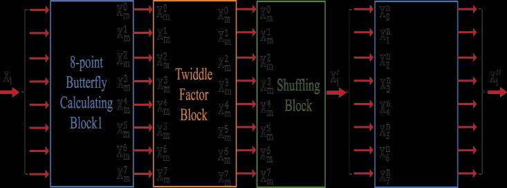
2.2. BPU Based on Radix 2 Fig 2: Block diagram of Radix 2. Fig. 2 shows the block diagram of radix 2 butterfly calculating cell, in which two points and a twiddle factor are input. The butterfly calculation based on radix 2 algorithm contains one complex multiplication, which consists of four real multiplications. The butterfly calculating cell is implemented by four multipliers, three adders, and three subtractors. After the multiplication operation, we take the most four significant bit (thesame inthefollowing).Aneight pointbutterflycalculatingblock basedonradix 2algorithmincludes12radix 2butterfly calculatingcells.
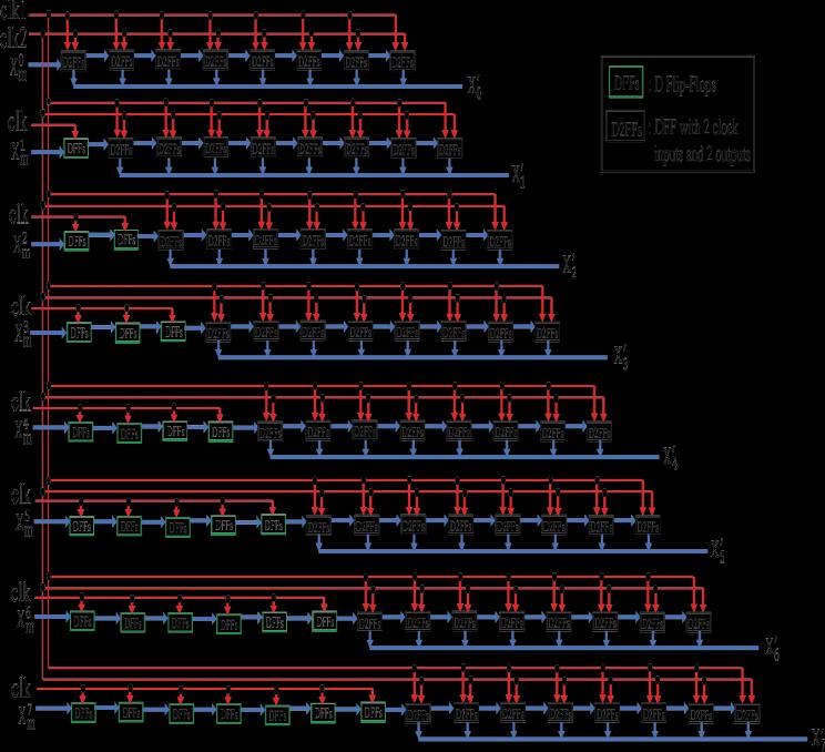
There are 2 styles of FFT algorithms: decimation in time (DIT)Anddecimation in frequency (DIF). DITis multiplying twiddle factors 1st and bit reversed for its input. DIF is doing butterfly operation 1st and bit reversed for its output. In this article, the dot algorithmic program is adopted to implement the projected BPUs.Unlike the antecedently developed bit serial RSFQ BPUs, the proposed bit slice BPUs ceaselessly method bit sliced 64 pointknowledgedividedintoeightslicesofeightpurposes everysoastoincreasetheoutturnofprocessorsandscale back the hardware cost. The computer file length is four bits, that is split into 2 slices of two bits every to be processed.
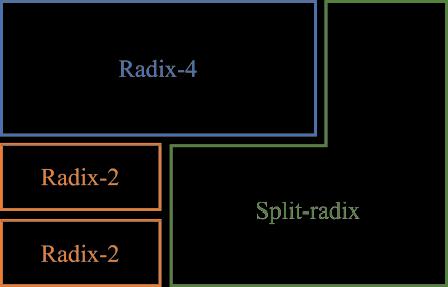
Fig.-3: Block diagram of radix-4 butterfly calculating 2.3. BPU Based on Split Radix Split radixalgorithmcombinestheradix 2andradix 4algo rithms.Aradix 4algorithmisfortheoddtermsoftheFFT, andradix 2algorithmisfortheeventermsoftheFFT.
Fig.3showstheblockdiagramofradix 4butterflycalculating cell, in which four points and three twiddle factors are input. The butterfly calculation based on radix 4 algorithmcontain.
Fig. one shows the diagram of the BPUs. It’s composed of 2 butterfly shrewd blocks, a twiddle issue block, and a shuffling block. The block diagrams of BPUs supportedradix 2,mixed radix,andsplit radixalgorithms are an equivalent. In order to confirm the total capability of the BPUs, two same butterfly shrewd blocks are used. Every butterfly shrewd block contains totally different numbersofbutterflycells. The number of butterfly calculating cells depends on which algorithmisadopted. Thedetailsofthethreetypes ofbutterflycalculatingcellswillbeshownlater. The64 pointFFTiscarriedoutthrough12steps.Atsteps 0 7,the64 pointdataaredividedintoeightslicesofeight pointseach. The ithslice,i.e.,Xi (0 ≤ i ≤ 7),isinputone byoneintothe eight pointbutterflycalculatingblock1atstep i.Theeight pointsof ithsliceinclude X(i),X(i +8),X(i +16),X(i +24),X(i + 32),X(i + 40),X(i + 48),X(i + 56), where 0 ≤ i ≤ 7. The input order of the eight points is determined by the algorithm used in butterfly calculating cells. According to radix 2algorithm.
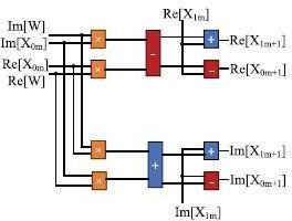
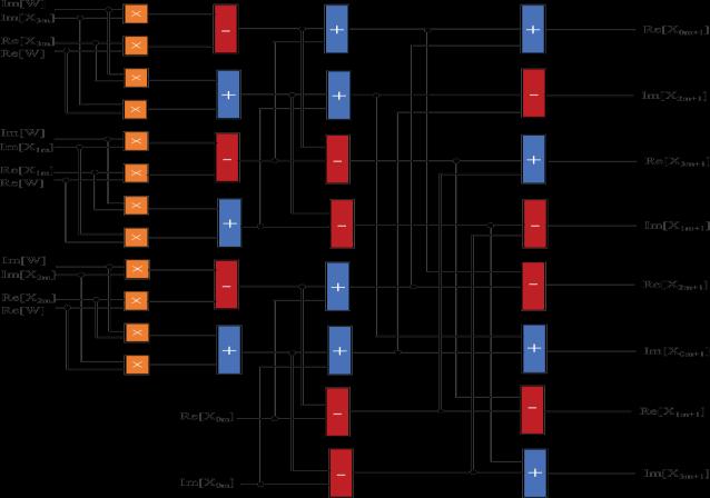
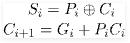
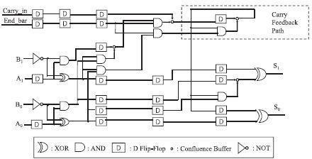
Fig 6: Logic design of the adder used in butterfly calculating cell.
Thebutterflycalculatingblockscontaindifferentnumbers of butterfly calculating cells. The butterfly calculating cells are implemented by adders, subtractors, and multipliers. Fig. 6 the logic gate level circuit of the adder usedinbutterfly.
International Research Journal of Engineering and Technology (IRJET) e ISSN: 2395 0056 Volume: 08 Issue: 12 | Dec 2021 www.irjet.net p ISSN: 2395 0072 © 2021, IRJET | Impact Factor value: 7.529 | ISO 9001:2008 Certified Journal | Page1589
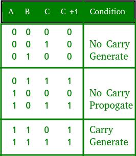
Consider the complete adder circuit shown higher than with corresponding truth table. we tend to outline 2 variablesas‘carrygenerate’and‘carrypropagate‘then,
Byexploitingtheradix 2,radix 4,andsplit radixbutterfly calculating cells, we have designed the BPU based on split radix
Fig 5: Block diagram of the eight point butterfly calculation based on split 2.4. BPU Based on Mixed Radix AsshowninFig.5,split radixalgorithmusesdifferentradices in the same stages. Mixed radix algorithm uses different radices indifferentstages.Fig.6 shows theblock diagram of the eight point butterfly calculation based on mixed radix algorithm. Aneight point butterfly calculating block based on mixed radix algorithm includes two radix 4 butterfly calculating cells and four radix 2 butterfly calculatingcells. 2.5. Logic Design Concurrent flowclockingisadoptedtodesignfullypipelined synchronous RSFQ logic circuits of the proposed BPUs. DFFsareusedtoensurethesynchronizationofthedatain the BPUs.The basic RSFQ logic gates, wirings and flip flops: AND, XOR, NOT, DFF, D2FF, NDRO, SPL (splitter), and confluencebuffer(CB) in the cell library [15] for the AIST ADP2withacriticalcurrentdensityof10kA/cm2 [16]are used.Thedelayandjunctioncountofeachlogicgate
Fig 4: Block diagram of split radix butterfly calculating cell. Three complex multiplications. The butterfly calculating cell is implemented by 12 multipliers, 11 adders, and 11 Fig.subtractors.4shows the block diagram of split radix butterfly calculating cell, in which four points and two twiddle factors are input. The butterfly calculation based on split radix algorithm containstwocomplexmultiplications.The butterfly calculating cell is implemented by eight multipliers,sixadders,andsixsubtractors.
Table 1: Truth Table for Carry Look Ahead Adder
WehavedesignedRSFQcircuitsofthebit sliceBPUsbased On radix 2, mixed radix, and split radix algorithms. The number of multipliers, adders, and subtractors used in the BPUs. Fig 8: Logic design of shuffling block. 10 GHz which is assumed to calculate the latency of the proposedFFT BPUs. The calculation of the semiconductor FFT processor to complete 64 point 4 bit FFT needs 264 cycles at 600 MHz [18], whereas the calculation of the RSFQFFTprocessorbasedontheproposedFFTBPUusing split radix algorithm needs 189 cycles at 10 GHz. It is obvious that the performance of the RSFQFFT processor based on the proposed FFT BPU is better than the CMOS FFTprocessor.
3. DISCUSSION
TheBPUsbasedonmixed radixandsplit radixalgorithms consist of 173 stages in total. The slices of input data are fedatthe1sttothe16thclock cycles,andtheslicesofthe resultare outputatthe174thtothe 189thclockcycles. The calculation for 64 point BPUs based on mixed radix and split radixalgorithmsneeds189clockcycles.
International Research Journal of Engineering and Technology (IRJET) e ISSN: 2395 0056 Volume: 08 Issue: 12 | Dec 2021 www.irjet.net p ISSN: 2395 0072 © 2021, IRJET | Impact Factor value: 7.529 | ISO 9001:2008 Certified Journal | Page1590 Fig 7: Logic design of the subtractor used in butterfly calculating cell
Table 2 4.2.
5. CONCLUSION
WehavedesignedRSFQlogicgatelevelcircuitsofthe bit slice BPUs based on radix 2, mixed radix, and split radix algorithms. The results show that the split radix BPU hasthe lowest hardware cost and latency at 10 GHz. It consistsof 86 multipliers, 66 adders, and 66 subtractors. It contains173 pipeline stages, a total of 147 778 JJs, and a latency of20 292.4 ps. According to the physical schematic designs we havedesigned,thehardwarecostof physical schematic designs is three times that of logical designs.Basedontheestimationoftheinterconnection,the maximumclockfrequencyis75GHz.
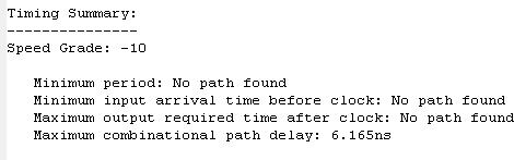
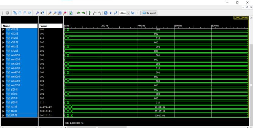
4. 4.1.RESULTSAREA DELAY Fig 9: Output Waveform
[12] A. Mukhanov and A. F. Kirichenko, “Implementation ofaFFTradix2butterflyusingserialRSFQmultiplier adders,” IEEE Trans. Appl. Super cond., vol. 5, no. 2, pp.2461 2464,Jun.1995.
[4] P. Duhamel and H. Hollmann, “Split radix FFT algorithm,”Electron.Lett.,vol.20,no.1,pp.14 16,Jan. 1984.
[7] Y. Ando, R. Sato, M. Tanaka, K. Takagi, N. Takagi, and A. Fujimaki, “Design and demonstration of an 8 bit bit serial RSFQ microprocessor: CORE e4,” IEEE Trans.Appl.Supercond.,vol.26,no.5,Aug.2016, Art. no.1301205.
[9] G.Tang,K. Takagi,andN.Takagi,“32 32 bit4 bitbit slice integer multiplier for RSFQ microprocessors,” IEEETrans.Appl.Supercond.,vol.27,no.3,Apr.2016, Art.no.1301005.
[10] G.Tang,P.Qu,X.Ye,andD.Fan,“Logicdesignofa16 bit bit slice arithmetic logic unit for 32 /64 bit RSFQ microprocessors,” IEEE Trans.Appl. Supercond., vol. 28,no.4,Jun.2018,Art.no.1300305.
[6] Y. Yamanashi et al., “Design and implementation of a pipelined bit serial SFQ microprocessor, CORE1β,” IEEE Trans. Appl. Supercond., vol. 17,no. 2, pp. 474 477,Jun.2007.
[5] K. K. Likharev and V. K. Semenov, “RSFQ logic/memory family: A new Josephson junction technology for subterahertz clock frequency dig ital systems,” IEEE Trans. Appl. Supercond., vol. 1, no. 1, pp.3 28,Mar.1991.
[8] G. Tang, K. Takata, M. Tanaka, A. Fujimaki, K. Takagi, andN.Takagi, “4 bit bit slicearithmeticlogicunitfor 32 bit RSFQ microprocessors,” IEEE Trans. Appl. Supercond.,vol.26,no.1,Jan.2016,Art.no.1300106.
[11] Tang,P.Qu,X.Ye,D.Fan,andN.Sun,“32 bit44bit slice RSFQ matrix multiplier,” IEEE Trans. Appl. Supercond.,vol.28,no.7,Oct.2018,Art.no.1300905.
[1] J. W. Cooley and J. W. Tukey, “An algorithm for the machine calcula tion of complex Fourier series,” Math.Comput.,vol.19,pp.297 301,Apr.1965.
[3] C. S. Burrus and P. W. Eschenbacher, “An in place, in orderprimefactorFFT algorithm,” IEEE Trans. Acoust., Speech, Signal Process., vol. ASSP 29, no. 4, pp. 806 817,Aug.1981.
[2] S.Winograd,“OncomputingtheDFT,”Math.Comput., vol.32,no.1,pp.75 199,Jan.1978.
International Research Journal of Engineering and Technology (IRJET) e ISSN: 2395 0056 Volume: 08 Issue: 12 | Dec 2021 www.irjet.net p ISSN: 2395 0072 © 2021, IRJET | Impact Factor value: 7.529 | ISO 9001:2008 Certified Journal | Page1591 REFERENCES