International Research Journal of Engineering and Technology (IRJET) e ISSN: 2395 0056 Volume: 08 Issue: 12 | Dec 2021 www.irjet.net p ISSN: 2395 0072 © 2021, IRJET | Impact Factor value: 7.529 | ISO 9001:2008 Certified Journal | Page1572 Deflection Reduction in C-Structure of a 50 Ton Hydraulic Press Machine Used to Press Stainless Steel Plates to Get Desired Shape and Dimensions Prof. S. V. Tawade1 , Dr. R. J. Patil2 , Prof. S. A. Chaudhari3 1Asst.Professor, Dept. of Mechanical Engineering, Navsahyadri Engineering College, Pune, India 2Principal, Navsahyadri Engineering College, Pune, India 3Asst. Professor, Dept. of Mechanical Engineering, Navsahyadri Engineering College, Pune, India *** Abstract
1. INTRODUCTION
Nowadays many pressure vessel components are manufactured by pressing operation i.e., by the use of hydraulicpressmachines.Sincehydraulicpressgivesmore pressingpower.Thedesiredshapesareobtainedbypressing operation. Usually Hydraulic press machines having C structuresareused.Themostimportantfactorsingetting desired shapes by pressing operation depends upon the accuracyofdies,thepressforceappliedandthedeflectionin theC structureofhydraulicpressmachineduringoperation. TheremustbeverynegligibleamountofdeflectionintheC structureofthehydraulicpressmachines;otherwise,itleads to the defective products. Our present work deals with reductionindeflectioninC structureofa50Tonhydraulic press machine to get the desired dimension and shape of outerlidcomponentofapressurevessel.Thecomponents manufactured by pressing operation undergoes different kindsofforcesandpressures.So,itbecomesveryessential to get the desired dimensions and shapes with more accuracy. The deflection in C Structure of hydraulic press machinesalsodependsupontheamountofforceapplied,the stresses acting on the structural parts, thickness of plates used,typesofweldsandthenumberandpositioningofribs. Inourpresentworkweanalysedthestructurecarefullyand modifiedthepositioningandthicknessofribsinC structure of50TonHydraulicpressmachine.Bythesemodifications we become successful in reducing the deflection of the C structure of 50 Ton hydraulic press machine in operating conditions. Also achieved the results in getting desired
Key Words: C Structure,HydraulicPress,Ribs,Deflection
A hydraulic press machine with 50 Ton capacity having C structure is used forpressingstainless steel plates for getting desired shapes of outer lid component of pressure vessels by a firm. The firm has a problem in getting desired shape of outer lid component of pressure vessels from the stainless steel plates. The present work deals with the identifying and rectifying the problems in getting desired shapes of outer lid component of pressure vessels after pressing operation on stainless steel plates using the 50 Ton capacity hydraulic press machines. The desired overall dimensions of the outer lid component of pressure vessel are Diameter of 155 mm and height of 40 mm. The outer lid material is stainless steel. There were no any issues with the dies used in pressing operation. But it is observed that there were some dimensional errors and shape errors in pressed outer lid components. Also, we observed that there is more deflection in C structure while in operation. So, the main objectives of the present work are solving the issues and also the reduction in deflection of the C structureof50 Toncapacityhydraulic press machine. We observed the response of loading conditions on the C Structure of the Machine. Under operatingconditions,themachinestructurewill undergo deflection. But the deflection should be very minute or negligible so that the pressing operation will be smooth. The ribs welded to structure have 25 mm of thickness. We modified the rib dimensions and their spacing. Two design calculations aredonefortheamount ofdeflection occurring in the structure. One by considering 30 mm thick ribs and another by considering 50 mm thickness, ribs of the same material as that of the main structure. The structure is analyzed for deflection by analytical method and also using Autodesk Inventor software. The deflection of the C structure was reduced from 0.08mm to 0.025 mm. Deflection in the C structure for 30 mm thickness ribs was 0.025 mm. The structure is modified by welding process by considering new dimensions of ribs i.e., 30 mm thick ribs. With this modifiedC Structure in hydraulic press machine of 50 Ton Capacity again stainless steel plates were pressed to get the desired shape and dimensions of outerlidcomponent ofpressure vessel. With this new C structure in hydraulic press machine we got the desiredshapeofouterlidcomponent of pressure vessels. The desired dimensions and shape were obtained. The results found was satisfactory and within the limits. Also, we become successful in reducing the deflection in C structure from 0.08mm to 0.025mm. The objectives of the present work are fulfilled successfully.

International Research Journal of Engineering and Technology (IRJET) e ISSN: 2395 0056 Volume: 08 Issue: 12 | Dec 2021 www.irjet.net p ISSN: 2395 0072 © 2021, IRJET | Impact Factor value: 7.529 | ISO 9001:2008 Certified Journal | Page1573 shapesanddimensionsofouterlidcomponentofapressure vessel.Theperformance of a hydraulic press depends largely upon the behaviour of its structure during operation. However,theseweldedstructuresarebecomingcomplicated andtheiraccurateanalysisundergivenloadingconditionsis quiteimportanttothestructuredesigner.Hence,itisfound that optimal design of a hydraulic press in terms of its weightandtheamountofdeflectioninoperatingconditions aretheneedofthehour.Thesehydraulicpressesfindample applications in various industries. To count a few, the applications of hydraulic presses are Blanking, Clamping, Coining, Compacting, Compression Moulding, Drawing, Embossing, Forging, Forming, Injection Moulding, Powder Compacting, Punching, Spotting, Stacking, Stamping, Steel RuleDieCutting,Fulltonnagethroughoutthestrokeunlike mechanical presses, hydraulic presses have the ability to deliverfullpressingforceanywhereintherangeofstroke.It iseasytodesignthehydraulicpresstomeetthecustomers' specific requirements such as large bed sizes with little tonnageorhightonnagefor smallwork area.Inhydraulic press,usersareabletoadjusttonnageandmaximizecycle time. More efficiency can be achieved by eliminating excessive ram movement or changing pressure or maintainingramspeeds.Hydraulicpressesarethesimplest in design with proven, readily available hydraulic components. Unlike mechanical presses where basic componentsareexpensiveandoftencustombuilt,hydraulic pressesaremuchlessexpensiveup frontinfabrication.C structureisusedinahydraulicpressmachine.Pressworks onPascal’sprinciple,whichstates “pressure throughout a closed system is constant.” In hydraulicpress,thereisa pistonatoneendofthesystem having a small cross sectional area. The performance of hydraulicpressdependsuponthebehaviourofitsstructure duringoperation.Howeverduetocomplicatedstructureand variationofload,completestructuralknowledgeisessential to develop fail proof system. A very efficient fluid power transmissionsystemisusedinhydrauliccylinders.Present conventional power transmission systems are being replaced and being changed over to fluid power based systems[1].Inhydraulicpressmachines,press bodyisofC structure. When free space required from three sides of press table to work for loading and unloading of pressed component then this type of presses is designed. As main cylinder placed eccentric to central axis of press body, it applies eccentric load on press body hence heavier press bodyisrequiredascomparedtosamecapacityofothertype ofpress[2].Ahydraulicpressisamechanicalmachineused forliftingorcompressingvariouspartsandcomponents.The forceisgeneratedbytheuseofhydraulicfluidstoincrease the pressure inside the cylinder. The hydraulic press machine works on Pascal's principle [3]. The hydraulic cylinder is a device which used to convert fluid power to mechanicalpowerbyPascalprinciple.ThePascalprinciple states that pressure exerted anywhere in a compressible fluidistransmittedequallyinalldirectionthroughthefluid. In hydraulic cylinder a confined incompressible fluid pressureexertonthreesurfaces,cylinderwall,cylinderbase plateandpistonhead[4].InANSYSwecanapplyloadson the model in a variety of ways. By using load step option, during solution we can control use of loads. A C type hydraulicpressisamachinethatsuppliesforcetodieused to,form,blankorshapemetalornon metallicmaterials.The Metalformingmanufacturingprocessarealmostchipless. Presstoolsareusedtocarryoutthisoperation.Deformation ofworkpiecetodesiredsizeisdonebyapplyingpressure.In thisprojectCframetypehydraulicpressaremainlyusedfor sheet metal punching. It consists of bed, frame or bolster plateandareciprocatingmembercalledasslideorram[9]. Becauseofcontinuousimpactload,frameofpressmachine alwaysexperiencescontinuoustensilestress.Pressmachine continuousdealswithstressandbecauseofthatfrequently structural failure problem occurred in machine. It is also helpfultoreducethicknessofplateofframestructuresothat materialsavingandcostbenefitwillbeconsiderable.Itcan beconcludedthatsimulationsoftwareisthepowerfultool for prediction of the thickness of plate required for given load [10]. To develop the C structure of the machine, Autodesk Inventor software is used. With the help of this software a 3D CAD model was developed along with the simulationof theC Structure.Structural analysisofthe C structureiscarriedoutusingFEMtechnique.Pressmachine alwayssubjectedtoheavyimpactloadcondition. 2. DESIGN CALCULATIONS OF C STRURCTUE [8] Byusingribthicknessasa30mm AreaA1 =1000×30=30,000mm2 AreaA2 =125×(400 30)=46,250mm2 AreaA3 =50×(750 400)=17,500mm2 y=DistanceofC.G.ofthesectionfrombottom y1 =15mm,y2 =215mm,y3 =575mm ȳ=(A1y1+A2y2+A3y3)/(A1+A2+A3) (=(30000×15+46250×215+17500×575)/30000+46250+17500) ȳ=218.2mm I=Ixx1 +Ixx2 +Ixx3 Ixx1 =IG1+A1h2 =(1000×303 )/12+(30000×(218.2−15)2) =1240.95×106 kgmm2 Ixx2=IG2 +A2h2 =(125×3703 )/12+(46250×(218.2 215)2) =528.109×10⁶ kgmm2 Ixx3=IG3 +A3h2 =(3503×50)/12+(17500×(575 218.5)2 ) =2406.505×106 kgmm2 I=4175.564×106 kgmm2 σ=Mȳ/I =(50000×500×218.2)/(4175.564×106) =13.06N/mm2 δ=Pl3/3EI
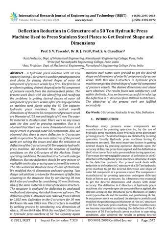
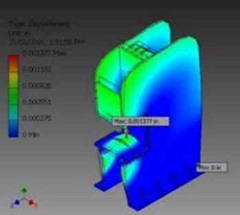
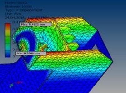
4.3 Analysis: Inthiscaseweappliedmostoftheloadseither on finite element model(on elements and nodes)or on thesolidmodel(onlines,keypointsandareas).Thus,onkey points or on a node force can be specified. After applying boundarycondition,Structuralanalysisisdonetofindstress anddeflection.Themainaimofthecustomerwastogetthe productofgoodqualitywithdesiredshapeanddimension. We modified the C structure by varying spacing and thicknessofribs.ModeliscreatedinAutodeskInventor.To meshtheC structureofthemachine,8nodeswith2Degree ofFreedomisused. After applying boundary condition, Structural analysis is donetofindstressanddeflection.Anattemptwasmadeto analyzethe50TonC typehydraulicpressusingAutodesk Inventor software. It is successfully designed to meet the requirements as per the constraints. The C type hydraulic pressframeiscarefullydesignedandcrosscheckedwhereit does meet the requirements. The stresses and the displacementsareshowninfigures(Fig.1toFif.4)
4.2 Boundary Conditions: Either on the finite element model entities or on the solid model entities we can apply the majority of the boundary conditions and excitations to a harmonic high frequency analysis. Since applying boundary conditions to the solid model is beneficial. We observed the response of loading conditionsontheC StructureoftheMachine.Specifyingthe correctloadconditionsisveryimportantstepinouranalysis. InAutodeskInventorwecanapplyloadsonthemodelina varietyofways.Byusingloadstepoption,duringsolutionwe can control use of loads. In this case load is applied to cylinderramandimpactforceinappliedtothebedorwork tablealongwiththebaseofthehydraulicpressinfixed.50 ton load is applied on the structure where the hydraulic cylinderramistobeplaced.
Figure 1. Displacement Analysis of C Structure
International Research Journal of Engineering and Technology (IRJET) e ISSN: 2395 0056 Volume: 08 Issue: 12 | Dec 2021 www.irjet.net p ISSN: 2395 0072 © 2021, IRJET | Impact Factor value: 7.529 | ISO 9001:2008 Certified Journal | Page1574 =50000×5003/(3×200000×4175.564×106) =0.0249mm Byusingwidthof50mm Areaofsection'a'=1000×50=50,000mm2 Areaofsection'b'=125×450=56,250mm2 Areaofsection'c'=50×500=25,000mm2 y=DistanceofC.G.ofthesectionfrombottom y1 =25mm,y2 =275mm,y3 =750mm ȳ=(A1y1+A2y2+A3y3)/(A1+A2+A3 00)=(50000×25+56250×275+25000×750))/(50000+56250+250 ȳ=270.23mm I=Ixx1 +Ixx2 +Ixx3 Ixx1=IG1+A1h2 =(1000×503/12)+(50000×(270.23−25)2) =3017.29×106kgmm2 Ixx2=IG2+A2h2 =(125×4503/12)+(56250×(275−270.23)2) =950.48×10⁶kgmm2 Ixx3=IG3 +A3h =(50×5003/12)+(25000×(750−270.23)2) =7234.48×106kgmm2 I=11202.25×106 σ=Mȳ/I =(500350×270.23)/11202.25×106 =6.03N/mm2 δ=Pl3/3EI =500350×5003 /3×208000×11202.25×106 δ=0.008947mm 3. DESIGN CALCULATIONS OF HYDRAULIC CYLINDER [7] Force=PressurexArea F=P×A FWere,=Appliedforce=50x103 kg P=Pressure=100kg/cm2 A=PistonArea=����2/4 NowF=PxA 50x103 =100x����2/4 500��4=��d2 d2 =636.6197 d=25.23≈30.00cm 4. STRESS AND DEFLECTION ANALYSIS OF C STRUCTURE 4.1 Meshing: ThemodelingofsolidC Structureissettogeneratethefinite elementmesh.Theelementsize,elementshapeandmidsize placementofnodeisusedinmeshingofthesolidmodeland isestablishedbyusingmeshingcontrols.Thisstepisoneof the most important parts of our entire analysis, for the decisionswemakeatthisstageinourmodeldevelopment willprofoundlyaffect the accuracy of our analysis. Tomeshthemachine,8nodeswith2DegreeofFreedomare used.
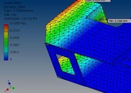
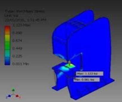
International Research Journal of Engineering and Technology (IRJET) e ISSN: 2395 0056 Volume: 08 Issue: 12 | Dec 2021 www.irjet.net p ISSN: 2395 0072 © 2021, IRJET | Impact Factor value: 7.529 | ISO 9001:2008 Certified Journal | Page1575 Figure 2. Stress Analysis of C Structure Figure 3. Displacement Analysis of C Structure Figure 4. Displacement Analysis of C Structure 5. RESULTS AND VALIDATION Table 1. Materials of construction [6] Table 2. Results Comparison [5] ptionDescri resultTheoretical Analysis Results from InventorAutodesk MaximumStress MaximumDeflection mMaximuStress DeflectionMaximum eStructurC- 2N/mm6.03 mm0.0249 N/mm7.742 mm0.034798 6. CONCLUSIONS Hydraulic press is the most efficient among the different typesofindustrialpresses.Hydraulicpressesoperateonthe principles of hydrostatic pressure to transmit power. Minimal deflection design for rigidity and long life of structureisrequired.Deflectioninstructuredependsupon the applied amount of force and the bending stresses developed in the structure. C Structure of the machine is subjected to different types of loading conditions and is analyzedusingAutodeskInventortool.Thematerialofthe structureismildsteel.TheC structureofa50Toncapacity hydraulicpressismodifiedbywelding30mmthicknessribs to the structure to make the structure strong enough and reducethedeflection.Initiallytheribthicknessusedwasof 25mm thick but we modified the thickness to 30mm. Our aim was to control deflection of C structureunder 0.0100 mmandwebecomesuccessfulinreducingdeflectionofC structurefrom0.08mmto0.025mmbyvaryingthicknessof ribsform25mmto30mm.Ouronemoreobjectivewasto get the desired dimension and shape of stainless material outer lid component of pressure vessel. The desired dimensions are 155 mm diameter and 40 mm height. We achieved these desired dimensions after reducing the NoSr. Mild ParametersSteel Value Units 1 Density 7800 3Kg/m 2 Young’smodulus 200 GPa 3 Poisson’sratio 0.3 4 Yieldstress 410 MPa 5 UltimateTensile Strength 650 MPa
Journal
02
Applied Research · Volume : 3 | Issue : 7 | July 2013 |
2011
[5] S. M. Bapat and Dessai yusufali, “Design and Optimization of A 30 Ton Hydraulic Forming Press Machine”InternationalJournalForResearchinApplied ScienceandEngineeringTechnology(IJRASET),ISSN: 2321 9653,Vol.2IssueVIII,August2014.
[8]
Press”, International
03|
2015. [11] H.N.Chauhan, M.P.Bambhania “Design & Analysis of Frameof63TonPowerPressMachinebyUsingFinite Element Method” ndian Journal
International Research Journal of Engineering and Technology (IRJET) e ISSN: 2395 0056 Volume: 08 Issue: 12 | Dec 2021 www.irjet.net p ISSN: 2395 0072 © 2021, IRJET | Impact Factor value: 7.529 | ISO 9001:2008 Certified Journal | Page1576 deflectioninC Structurefrom0.08mmto0.025mm.From theoreticalanalysiswegotthestressvalueinC structureof 50 Ton hydraulic press machine as 6.03 N/mm2 and by analyticalmethodwegotthestressvalueas7.74N/mm2for 50TonLoading.ThemaximumdeflectioninC structureof hydraulic press machine by theoretical analysis, we got 0.0249mmandbyanalyticalanalysiswegotthemaximum deflectioninC structureofhydraulicpressmachineusedas 0.034798mm.TheC Structurewastestedforperformance with a load of 50 Ton and the results were found to be satisfactory.Thedimensionsofthestainless steelouterlid component of pressure vessel achieved were also satisfactory. REFERENCES [1] Rucha. S. Khisti, Manoj. M. Budhi, Abhijeet. Pawar, Shriganesh. K. Mangalvedhe” Design of C Frame for Assembly Press” International Journal of Engineering Research&Technology(IJERT),ISSN:2278 0181,Vol.4 Issue03,March 2015. [2] B.Parthiban , P.Eazhumali , S.Karthi , P.Kalimuthu “Design And Analysis of C Type Hydraulic Press Structure And Cylinder” International Journal of ResearchInAeronauticalandMechanicalEngineering, ISSN (Online): 2321 3051, Vol 2 Issue 3, March 2014, Pgs47 56.
[9] Engineering and
[3] AkshayVaishnav,PathLathiya,MohitSarvaiya“Design Optimization of Hydraulic Press Plate using Finite ElementAnalysis”Int.JournalofEngineeringResearch andApplications,ISSN:2248 9622,Vol.6,Issue5,(Part 4)May2016,pp.58 66 [4] Gebremichael Tasew, Ajay Jaswal, “Development of SingleHydraulicCylinderOperatedsheetmetalBending Machine”InternationalResearchJournalofEngineering and Technology (IRJET), e ISSN: 2395 0056, p ISSN: 2395 0072,Volume:05Issue:01,Jan 2018.
[7] GaneshMMudennavar,GireeshaChalageri,PrashantA. Patil,“DesignandAnalysisof12TonHydraulicPressing Machine”,ISSN:2455 2631,IJSDR|Volume3,Issue8, August2018 OptimizationBhushanV.Golechha,P.S.Kulkarni,“Design,Analysisandof10TONPneumaticPressMachine”, InternationalJournalofAdvancedResearchinScience, Technology,ISSN:2350 0328,Vol. SMore,ShreenidhiRKulkarni,“FiniteElement ‘c’TypesHydraulic200ton Research of Engineering and Technology (IRJET), ISSN: 2395 0056, p ISSN: 2395 0072,Volume: Issue: June of ISSN 2249 555X, October
[6] S.RajaShekar,A.C.UmaMaheshwarRao“Designand StructuralAnalysisofa1000TonHydraulicPressFrame Structure” International Journal of Research in Engineering,ScienceandManagementVolume 1,Issue 10,October 2018,ISSN(Online):2581 5792.
e
AnalysisandOptimizationof
4, Issue3,March2017 [10] Rangraj