This paper discusses how to achieve selectedmodaltomorerelatedstudiesdiskbrakerotor such as structural, transient structural, explicit dynamicandthermalsimulation.3Dmodelestablished bySolidworksisimportedintoANSYSWorkbench,and modal simulation analyses are carried out. It also presents a study of the different modal of the automobilediscbrakephase.Then,studyofpadmodal between the disc and pads is developed, simulation analyses are carried out. Using the maximum stress point and maximum deformation position under the emergencybrakingstate,combinedwiththeresultsof modal analysis cloud chart, the resonance range is verified by comparing with the natural frequency, which provides reference for the actual tests and structuralimprovement.
International Research Journal of Engineering and Technology (IRJET) e ISSN: 2395 0056 Volume: 08 Issue: 12 | Dec 2021 www.irjet.net p ISSN: 2395 0072 © 2021, IRJET | Impact Factor value: 7.529 | ISO 9001:2008 Certified Journal | Page1560 Simulation of Disc Brake Rotor and Pad Using ANSYS Workbench Noha Muhammad Abd ElSalam1 , Prof Ibrahim Ahmed2 , Sameh Metwally3 , Mostafa Mohamed4 , Ahmed Abdallah Hussien5, Essam Morsy6 1Researcher, Automotive and Tractors Engineering Department, Faculty of Engineering, Helwan University, Egypt 2Professor at Automotive Engineering Department, Helwan University, Egypt 3Professor at Automotive Engineering Department, Helwan University, Egypt 4Doctor at Automotive Engineering Department, Helwan University, Egypt 5Automotive Department, Helwan University, Egypt 6Professor at Automotive Engineering Department, Helwan University, Egypt *** Abstract
Brakes are mechanical device for increasing the frictional resistance that retards or stops the turning motionofthevehiclewheels.Itabsorbskineticenergy andtransformsittoheat.Thebrakesmustbecapableof deceleratingthevehicleatfasterratethantheengineis abletoaccelerateit.Brakeperformanceisimprovedby increasingfriction,sothefrictioncoefficientplaysan important role in the braking process [1]. The pedal force,whichisgeneratedasaresultofthedriverdesire, is the input and the brake or friction force is as the output.Thehydraulicforceisconvertedtothe brake force with an amplification factor called the characteristicbrakefactor[2].Whenthedriverstepson thebrakepedal,hydraulicfluidispushedagainstthe piston of the caliper, which in turn forces the brake padsintocontactwiththerotor.Thefrictionalforcesat theslidinginterfacesbetweenthepadsandtherotor retard the rotational movement of the rotor and the axleonwhichitismounted.Thekineticenergyofthe vehicle is transformed into heat which is mainly absorbed bythe rotor and the brakepad. To ensure robustbrakeperformancesomebrakesystemsrequire thepadstofrequentlybeinlowpressurecontactwith therotor.Thisdraggingremovesanyoxidelayer(e.g. rust) from the rotor and keeps the contact surfaces clean.However,theresultingdragtorqueisadrawback asitincreasesfuelconsumption.Thereforethedragging shouldbereducedwithoutaffectingtheperformanceof the brakes. It is important to be able to predict the pressure and time needed to wear off the unwanted oxidelayers[3].Thispaperdiscusseshowthiscanbe doneusinggeneralpurposefiniteelementsoftware.A threedimensionalfiniteelementmodelofthepadand rotorisdesignedtocalculatethepad to rotorpressure distribution. A wear simulation process based on a generalizedformofArchard’swearlawandtheEuler integrationschemeisusedtosimulatethewearofboth surfacesofthecontactpair.Theproblemsofdiscbrake arethenoise,vibrationandcorrosion.
ThemaincomponentsofaDiscbrakeare:
Brakepads Calipers,containingpiston Discbrakerotor Fig. 1:Discbrakeandcomponents.
Key Words: Disc brake, SolidWorks, ANSYS, Cast Iron,1.Steelformatting.INTRODUCTION


Finite element analysis
Frictional brakes: Friction brakes are the most commonlyemployedbrakingsystemincommercialor special purpose vehicles. They generally are rotating devices with a rotating wear surface like Disc and a stationarypad.Here,thekineticenergyofthemoving vehicleisutilizedtostopthevehiclebyconversionof thiskineticenergyintoheatenergy/frictionalenergy [5]. A few common configurations of this type of braking are disc brakes, drum brakes and hydrodynamicbrakes.
3. NATURAL FREUENCY OF PAD / DISC
Disc brakes: Shoes or pads contract and provide compressivefrictionalforceontheoutersurfaceofa rotating Disc. It is a circular metal Disc on which the pads are mounted. Usually it is made up of cast iron material.ThedesignofDiscbrakesisvarieddepending on the application, amount of exposure, thermal properties of the material and the amount of heat dissipationrequiredwhenbrakesareappliedandthe totalmasstobestopped[6].
Theory of disc brake
The main objective of this work understands the work of brake system, mechanics, structural rigidity and low stress materials to design a new model and optimizethisdesign.Adiscbrakeisdesignedbyusing Solidworks and also is carried out by using finite elementanalysis(FEA).Thusthevaluesofshearstress, total deformation and distribution on disc brake are obtained.
Design model
The finite element method is a powerful tool to obtain the numerical solution of wide range of engineering problems. This method is generally sufficienttohandleanycomplexshapesorgeometries, foranymaterialunderdifferentboundaryandloading conditions.Thegeneralityofthefiniteelementmethod fitstheanalysisrequirementofpresentdays
Thediscbrakeassemblyusedinthisstudyconsists ofthreemajorcomponents,thecaliper,thediscandthe pads.Thecaliperinteractswiththeinnerpadviathe pistonandwiththeouterpadviathepaw.Bothpads are prevented from circumferential motion by the abutmentswhichcanoperateeitherontheleadingor trailingedgeofthepadoronboth.Thecontactatthese external connections is modeled as stiff springs thus avoiding the need to include a caliper model in the stability analysis. The most active interactions occur between the pads and the disc and the pad disc interfaceisofutmostimportancebecausethisiswhere thecircumferentialfrictionforceexcitesthetransverse motion of the disc and the pads. Therefore it is necessarytodeterminethecontactareaandpressure distribution between the pads and disc for various conditions in order to provide the information for calculation of the contact stiffness magnitude and distributionforthesubsequentstabilityanalysis.
ThefrequencyofDiscbrakesbrakingnoiseismainly distributedin10~16000Hz[4],whichcanbedivided intolow frequencyvibrationnoise(10~1000Hz),high frequency vibration noise (>1000 Hz) which can be furtherdividedintoLow farSqueal (1000~3000 Hz) andHigh farSqueal(>3000Hz).
4. PRESSURE ANALYSIS OF THE DISC BRAKE AND STUDY OF CONTACT BRAKE PAD / DISC
Fig. 2:3Dmodel
Finiteelementmodelsstudyofthediscandthe padwhichdisplayacceptablecorrelationwith theavailableresults Study the natural frequency of the pad and rotordisc. Studythecontactpressuredistributionatthe pad and rotor disc interface under normal sliding conditions at one and two piston pressure. Suggest realistic and coherent strategies for eliminatingsquealatthedesignstageusingthe resultsoftheabovestudies. Compareresults.
Dimensions are taken from actual disc brake, to obtain a 3D model of the disc brake rotor. Used SolidWorksProgramstobuildanddesignmodel.Figure 2showsmodelofdiscbrake
International Research Journal of Engineering and Technology (IRJET) e ISSN: 2395 0056 Volume: 08 Issue: 12 | Dec 2021 www.irjet.net p ISSN: 2395 0072 © 2021, IRJET | Impact Factor value: 7.529 | ISO 9001:2008 Certified Journal | Page1561 2. OBJECTIVE

[M] ismassmatrix, [C] isdampingmatrix, [K] isstiffnessmatrix, isnodalaccelerationvector, isnodalvelocityvector, {u} isnodaldisplacement vectorand isloadvector.Atanygiventime t.
International Research Journal of Engineering and Technology (IRJET) e ISSN: 2395 0056 Volume: 08 Issue: 12 | Dec 2021 www.irjet.net p ISSN: 2395 0072 © 2021, IRJET | Impact Factor value: 7.529 | ISO 9001:2008 Certified Journal | Page1562
ThefiniteelementsANSYSWorkbenchisusedinthis sectiontosimulatethebehaviorofthemechanismof frictionalcontactoftwobodies(padanddisc)duringa stopbraking.Thiscodehasalgorithmsofmanagement of the contact with friction based on the method of Lagrangemultipliers,orthepenaltymethod.Thedisc brakeproducttypicallyincludesthefollowingsteps: BuildthemodelintheSolidWorks. Imported3DmodeltoANSYSWorkbench. Evaluatetheresultsofthetests.
FEM in the automotive industry is a tool to study stress in a complex structures. The matrix analysis methodusedinautomotivedesignhasgainedincreased popularityamongbothresearchersandpractitioners. The basic concept of finite element method is that a bodyorstructureisdividedintosmallelementsoffinite dimensionscalled“finiteelements”throughgeneration ofmeshes. The original body or the structure is then considered as an assemblage of these elements connectedatafinitenumberofjointscallednodesor nodal points. This analysis employs the technique of vibrationsandcalculustoproduceaccurateresults.
5. FEM USING ANSYS
Due to the special structure of the disc brake and pad,therearemanygroovesandchamfers.Inorderto ensurethequalityofmeshingandcalculationaccuracy, somesimplificationsaremadewhenimportingthe3D model.Theunittypeusedformeshingissolid186,and theunitisselected(mm,t,N,s,mv,mA).Thefinalresult isshowninthetable1and2.
Table 1 Modalanalysisdifferencerelatedtodifferent meshdensitiesfordiscrotor. Naturalfrequency(Hz)forthefollowing Meshelements19933 elements15016Mesh elements13142Mesh elementsMesh9383
Simulation of the problem ANSYS
complex engineering systems and designs where solutions of governing equilibrium equations are usuallynotavailable.Inaddition,itisanefficientdesign tool for designers can perform parametric design studiesbyconsideringvariousdesigncases,(different shapes, materials, loads, etc.). And analyze them to choosetheoptimumdesign.
Thesystemmodalanalysisprocessesareasfollows. Systemvibrationdifferentialequation: m,c and k representmass,dampingandstiffnessmatrix respectively; f(t) representstheloadfunctionchanged withtime; representsthenodeaccelerationvector; representsthenodevelocityvector;and represents thenodedisplacement. Thenaturalvibrationfrequency ofthe i orderand theeigenvector correspondingtothe i modalshape of the system can be calculated through the above is:time.responsewithequation.ThetransientdynamicstructuralanalysisperformedtheANSYSprogramdeterminesthestructure'stotasksthatvaryarbitrarily(randomly)overInatransientdynamicanalysisequationofmotionWhere,
Modal analysis of brake pad Modalanalysisisawayofcalculatingequationsby means of coordinate transformation, which mainly includesfourkindsofdynamiccharacteristicanalysis.
Thedefinitionistousethephysicalcoordinatesinthe vibration differential equation of the linear constant systemtobeconvertedintomodalcoordinatestosolve theequationsandobtainasetofindependentequations describedbymodalcoordinatesandmodalparameters.
It is a common method in today's research on the dynamic characteristics of structures. The analysis processandresultsareobtainedbythemethodoffinite element calculation, which is called computational modalanalysis.
Meshing


International Research Journal of Engineering and Technology (IRJET) e ISSN: 2395 0056 Volume: 08 Issue: 12 | Dec 2021 www.irjet.net p ISSN: 2395 0072 © 2021, IRJET | Impact Factor value: 7.529 | ISO 9001:2008 Certified Journal | Page1563 Table 2 Modalanalysisdifferencerelatedtodifferent meshdensitiesforpad. Naturalfrequency(Hz)forthefollowing Meshelements7099 Meshelements4735 Meshelements3736 Meshelements3573 Setting the material parameters in the material propertymoduleselectedthestructuralsteel1006and ironsteelmaterialthathasbeenset.Themainphysical propertyparametersofthismaterialareshowninthe table3. Table 3:Mechanicalcharacteristicofbrakeparts Properties Disc Pad Density( 7850 2800 Young’s Modulus (Pa) 2E+11 2.2E+9 Poison’sRatio 0.3 0.25 Load and restraint determination Defining constraints, apply full constraints on the centerholessurfaceofthebrakedisc, Fig 3. Constraintposition 6. Modal analysis process and results Themodalanalysisisexecutedinthemodalanalysis moduleofANSYSWorkbenchsoftware.Thegeometric model of the brake disc and pad are imported. The materialpropertiesaresetandthebrakediscandpad are meshed. The modal analyses results of the brake discandpadarefinallyobtained.Whenanalyzingthe modalresults,select1,5,10and20frequenciesvalues and mode description of the brake disc and pad as shownintable4. Table 4 Comparisonbetweenthesimulatedresults andvaluesforthemodelofdiskrotor. Case Mode1 FEA(Hz)value Modeshape 1 750.18 5 1636.5 10 3060 20 5733.8 Case Mode2 FEA(Hz)value Modeshape 1 761.38 5 1645.1


International Research Journal of Engineering and Technology (IRJET) e ISSN: 2395 0056 Volume: 08 Issue: 12 | Dec 2021 www.irjet.net p ISSN: 2395 0072 © 2021, IRJET | Impact Factor value: 7.529 | ISO 9001:2008 Certified Journal | Page1564 10 3076.6 20 5770.8 Case Mode3 FEA(Hz)value Modeshape 1 760.13 5 1644.3 10 3073.5 20 5767.2 Case Mode4 FEA(Hz)value Modeshape 1 763.74 5 1651.3 10 3099 20 5823 Fromtheabove,thelowestorderfrequencyandthe first order frequency of the brake disc are about 750.18Hz,761.38Hz,760.13Hz and763.74Hz.Dueto different brake structure, the modal analysis result shows the first and five order modal frequencies are closertothesquealfrequency. Table 5 Comparisonbetweenthesimulatedresults andvaluesforthemodelforpad. Case Mode1 FEA(Hz)value Modeshape 1 4190.3 2 9587.4


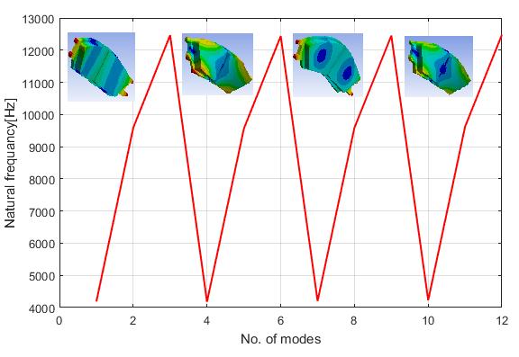
International Research Journal of Engineering and Technology (IRJET) e ISSN: 2395 0056 Volume: 08 Issue: 12 | Dec 2021 www.irjet.net p ISSN: 2395 0072 © 2021, IRJET | Impact Factor value: 7.529 | ISO 9001:2008 Certified Journal | Page1565 4 12465 Case Mode2 FEA(Hz)value Modeshape 1 4180.3 2 9556.7 4 12439 Case Mode3 FEA(Hz)value Modeshape 1 4204.9 2 9592.4 4 12453 Case Mode4 FEA(Hz)value Modeshape 1 4229.2 2 9620.9 4 12480 Table5showsthenaturalfrequencyofthepadsat1, 2and4modes.Theorderfrequenciesofthepadsare showninthetable4.Duetodifferentpadstructureand materials,themodalanalysisresultshowsthefirstand four ordermodalfrequenciesareclosertothesqueal frequency. Fig. 4. Frequencyforthediscrotor. Figure4showsrelationbetweenfourcasesatdifferent elementsizefordiskbrakerotor.


International Research Journal of Engineering and Technology (IRJET) e ISSN: 2395 0056 Volume: 08 Issue: 12 | Dec 2021 www.irjet.net p ISSN: 2395 0072 © 2021, IRJET | Impact Factor value: 7.529 | ISO 9001:2008 Certified Journal | Page1566 Fig. 5. FrequencyResponseFunctions forthediscrotor. Fig. 6. Frequencyforthepad. Fig. 7. FrequencyResponseFunctions forthediscrotor. 7. CONCLUSION
[6] Howtobuildbrakepadsfactory?One stopsolution by bull brakes! Volume5: Transport, Retrieved from:http://www.infovisual.info/05/013_en.html.
[4] Cao, Q., Ouyang, H., Friswell, M.I. (2004) Linear eigenvalue analysis of the disc brake squeal problem.Int.J.Nuwer.Meth.Eng.,61:1546 1563.
[1]
References Giri,N.K."AutomobileMechanics"RomeshChandra KhannaforKhannaPublishers,2007.
[2] Leber, M., Karheinz, B., Dusil, V. "Selbstversträkende Reibungbremse" Patent, DE 19539012A1,1998.
This research uses the finite element method to perform modal simulation analysis on the disc brake rotor and pad of the automotive. The rotor disc is presentedintheintervalof500 15000Hzresultsfor different mode shapes and analyzed. The results are compared.Itisconcludedthattherigidityrequirements are metinthe static analysis, but the brake squeal is prone to phenomenon. In the follow up analysis, the occurrence of brake squeal can be reduced from the aspectofstructuraloptimization.Therearemethodsfor reducing disc brake squeal through structural modifications.Soseveralmodificationsaresuggested forthediscandpadincludinggeometricalandmaterial modifications.
[5] DeatonJP(2008)Howbrakerotorswork?Part 2. Retrieved from parts/brakes/brakehttp://auto.howstuffworks.com/autoparts/brakerotors2.html
[3] ASöderberg,USellgren,SAndersson."Usingfinite element analysis to predict the brake pressure neededforeffectiverotorcleaningindiscbrakes".