● Usedinfurnituremaking ● FutureScope ○Itisusedinindustries. It is used with automation for automatic drilling. In the future it will be used in every field wheredrillingisrequired.○Alsousethismethod of rotation of the arm in other machining operations.
Key Words: 360 degree ,Precision , Accuracy ,Portable , 1.INTRODUCTIONDrilling
Every industryhas relied ondrill machinesto function. Drilling holes in parts, sheets, and structures is commonplaceinindustry.Drillingthatisperfectlyaligned and well aligned necessitates the use of fixed and powerfuldrills.Duetothesmalldistancebetweenthedrill bitandthedrill bed,somesectionscannot bedrilledwith
International Research Journal of Engineering and Technology (IRJET) e ISSN: 2395 0056 Volume: 08 Issue: 12 | Dec 2021 www.irjet.net p ISSN: 2395 0072 © 2021, IRJET | Impact Factor value: 7.529 | ISO 9001:2008 Certified Journal | Page1466 360 DEGREE DRILLING MACHINE Dr. Ravi kumar M1, Sri Jaivatsan M2, Sridhar S3 , Sujith S4 1Professor , Dept of Mechanical Engineering , Bannari Amman institute of technology , Tamilnadu ,India. 2 4UG Student ,Dept of Mechanical Engineering , Bannari Amman institute of technology , Tamilnadu , India. *** Abstract - Nowadays, the drilling machine is a rapid growth product with more uses and applications. Drilling machines are used to make the holes on the given workpiece. The Basic Drilling Machine efforts more constraints by limiting their movements and direction. There is a severe problem between drill and job which provides less space to make the holes. In this project, we are working on a 360 degree drilling machine to eradicate the problems by moving the drill in different locations. The precision and accuracy are higher in this Machine because the setup provides the proper straightness to the drill bit . This makes efficient holes on the workpiece rather than deformation in the drill bits. The 360 degree drill setup consists of different connecting arms which assists the movement of the drilling machine in horizontal, vertical and upside down direction which is mounted on a flat surface like a table provided with the swivel wheels. The caster locks are introduced to limit the movement of the drilling machine. The cost of manufacturing and setup is comparatively lower than other drilling machines. The feasibility of the project is expected to be good. The handling is easily done by the operator. This 360 degree drilling machine can be implemented to all the industries using drilling operations because of the selective axis and angle of drilling with the higher accuracy.
○
1.2 NEED OF THE STUDY
● To drill holes in engine heads, blocks, and cylindricalshellswithextremeprecision.
1.1 SCOPE OF OUR PROJECT
○
Drilling is the process of using metal cutting tools to make holes in a workpiece. Trepanning, counter boring, reaming, and boring are all machining techniques that includedrilling.Alloftheseprocesses,whenpairedwitha linearfeed,havethesamemovement.Shortholeanddeep holedrillingaretwoseparatetypesofdrilling.Thedrilling process can be related to turning in several ways but the requirements for chip breaking and chip evacuation are increasing.Indrilling,thisiscrucial.Theholedimensions, as well as the size of the hole, limit the amount of machining that may be done.The deeper the hole, it is more difficult to maintain process control. Along with quality, a high material removal rate is becoming increasingly important and dependable. The Aim of the project is to design and analyze the 360 Degree Drilling Machine which is more efficient than the conventional drilling machine. The main objective of the project is to drill holes horizontally, vertically and even upside down direction.Itcanbedrilledinanyaxisandanydegreewith the help of connecting arms setup. Due to this setup, we canachievemoreaccuracyofdrillingintheworkpieceand eradicate the different needs of different drilling machines. Selection of material plays an important role which should withstand the force and vibrations caused by the drilling operations. The components which are going to be used in the drilling setup also resists the vibration and make the setup rigid to make the drilling accurate. The cost of handling and manufacturing cost is low compared to the conventional drilling machine. This drilling machine is not needed by skilled laborers as it is easy to handle and operate the drilling machine. The highlight of this drilling machine which is portable as it has its own swivel wheels which provides the motion to the table. Due to its minimal space occupancy and more efficiency it can be applicable to the industries using drilling operations. It has the advantage of a portable drilling machine, as it can be portable to the desired drillinglocation.
Finally, complete content and organizational editing before formatting. Please take note of the following items whenproofreadingspellingandgrammar:

3.4
●
● HighWearresistanceandcuttingability.
3.2 MECHANICAL PROPERTIES
2. LITERATURE REVIEW
3.1 PHYSICAL PROPERTIES
●
The usual drilling machine has the heavy metals, drill bed for the workpiece, complex locomotive mechanisms for the drill machine movements whereasthe360degreedrillingmachine. Reasonableinitialcost,lowmaintenancecostasit cannot be replaced or repaired often and low productioncost.Byconsideringtheabovefactors, two materials selected for the study namely Mild Steel and High Speed Steel and their material propertiesaretabulatedinthetable3.4.
● HighTensileStrength Highfatiguestrength High fracture toughness and impact strength to restrictquickfracture. CORROSION RESISTANCE Low corrosion rate, this may increase the life of the360degreedrillingmachine. EASE OF MANUFACTURING
● Maintain high hardness upto temperature about 550°C and hence can be used for cutting metals andwoodsathighspeed.
●
3. MATERIALS AND METHODS
Table 3.4 : Mild Steel andHigh SpeedSteel andtheir material properties Properties Mild Steel HighSteelSpeed PhaseatSTP Solid Solid Densitykg/m3 8000 78160 Tensile(Mpa)Strength 440 1200 Yield(MPa)Strength 250 1000 Young’sModulus ofElasticity(GPa) 370 200 Brinell(BHN)Hardness 200 720 MeltingPoint(C) 1510 1430 Poisson'sRatio 0.3 0.3 ThermalConductivity (W/m.K) 15 41 Heat(J/gK)Capacity 460 470 4. DESIGN The design process was completely carried out in Autodesk Fusion 360. The 3D Modeling of the
Thematerialselectionbasedontheapplicationofthe360 Degree Drilling Machine, below are the requirements or the factors that influence the performance of the 360 Degree Drilling Machine and a wide study has been done beforeselectingthematerial.
●
International Research Journal of Engineering and Technology (IRJET) e ISSN: 2395 0056 Volume: 08 Issue: 12 | Dec 2021 www.irjet.net p ISSN: 2395 0072 © 2021, IRJET | Impact Factor value: 7.529 | ISO 9001:2008 Certified Journal | Page1467 fixed drills. In such instances, we must utilize hand drills, yethanddrillshavealignmentissuesduringdrilling.Sowe createda 360 degreedrill thatcanbemountedona table and used to drill holes horizontally, vertically, or even upsidedown.Asaresult,evendifficultpiecesandsurfaces canbeeasilydrilled.Thus,wedesignandbuildatiny360 degree drill for convenient drilling operations using rotating hinges and connectors, as well as a motor mount andsupportingframework.
●
G.N.Rakateetal.[1],discussedthepurposeofthiswork in 2016 to enhance the design and fabrication procedure of a Multiple Spindle Drilling Head in order to reduce the part's cycle time. They create a model that can drill two holes at once and has a variable center distance between thetwodrillingspindles.Anandhan,P.Gunasekaranetal, [2] discussed the purpose of this work in 2016. The key goal is to be able to rotate the drill in any direction with ease. As a result, work setup will be less complicated and setup time will be reduced. This method might be regarded as the most efficient method for manually controlling the drilling machine. This technology can drill wood, soft synthetic material, and light metals with ease. Mr.JayM.Pateletal.[3]discussedthispurposewithinthe durationof2015to2016.Itisbasedonathree directional drilling machine that drills holes based on their location andmovement.Theoperationcanbecompletedwithlittle effort, high precision, and accuracy thanks to this equipment. By minimizing total machining time, human labor, and manufacturing cycle time, this technology aids in increasing productivity. Lookesh kumar sahu, Pranesh kumar sahu et al. [4] discussed our purpose in the year 2018.Theauthorproposesa360 degreedrillingmachine thatcandrillhorizontally,vertically,orevenupsidedown in this work. In this machine, a twist drill bit made of carbon steel is employed. Nandewalia Prajal et al.[5] discuss the purpose of the year 2018.The author investigates the Graphical Drilling Machine. In this study, they propose that the drill machine may drill graphically inanydirection,withthedrillrotatingaroundtwoaxes(x axis & z axis). These drilling machines used to drill wooden works and metals. The primary goal is to cut down on machine time and vibration. Prof. Ms. A.A. Shingavi,etal
3.3
The table, swivel wheels, Connecting Arms, Drill machine, Tightening clamps and drill stand have beendesigned.
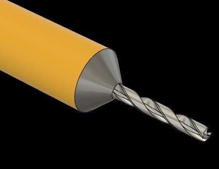
The Brad point drill bit is going to be implemented on thedrillingmachine.Hencethatdrillbitisdesignedforthe 360 Degree Drilling machine. The drill bits are based on the chuck capacity. We have already chosen the portable drilling machine and it's specifications. hence the 3mm
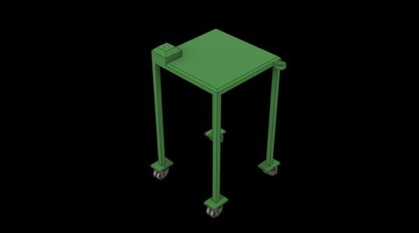
The table of the 360 Degree Drilling machine has two complications. The top of the table payloads the complete setup of the drilling machine and the bottom hasswivel wheelswhichshouldwithstandtheweight of thetableandsetupasshowninthe Fig 4.2.Theheightof the table is fixed as it achieves the required height (90 cm). The table is light in weight because of the material Mildsteel.Thetablewithstandsthevibrationscausedby thedrillingmachine.Fig4.2
Designoftable
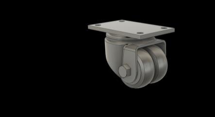
4.3 DESIGN OF CONNECTING ARMS
The design of the connecting arm is the major part of the study as it should be light in weight and withstand heavy loads caused by the weight of the drill machine and the arms should be proportional for equal weight distribution.Theconnectingarmshouldnotbedeformed or cause any failure during the drilling operations. This mayleadtotheslippageofthedrillbitandcausethenon functioning holes in the workpiece. There are three connecting arms in this design. Each 450 cm which is suitable height for all the drilling applications. The hollowbarsareappropriatefortheconnectingarmsdue to the advantage of resisting vibrations and lesser in weightthanthesolidbars.Eacharmhasitsownpurpose hencethecertainchangesdoneinFig4.3.
4.1 DESIGN OF SWIVEL WHEELS
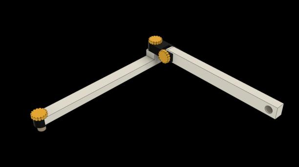
The design of the drilling clamp is based on the convenienceoftheoperator.Wecanusedifferentportable drilling machines which can be clamped at the end of the connecting arms. The tightening clamp is adjusted by the tighteningscrews.Thetighteningclamphastheadvantage of moving in two axis directions. For achieving higher efficiency, the holding bar is welded on the tightening clamps which is used to hold the drilling machine by the operator at the time of drilling operation .We designed a drillerwithclampwhichisshownintheFig4.4.
International Research Journal of Engineering and Technology (IRJET) e ISSN: 2395 0056 Volume: 08 Issue: 12 | Dec 2021 www.irjet.net p ISSN: 2395 0072 © 2021, IRJET | Impact Factor value: 7.529 | ISO 9001:2008 Certified Journal | Page1468
4.2 DESIGN OF TABLE
4.5 DESIGN OF DRILL BIT
4.4 DESIGN OF DRILLING CLAMP
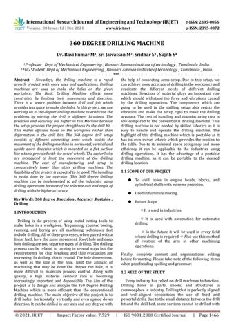
The swivel wheels have its own feature which is the basement and withstands the total weight on the top loads.Hencetheproperswivelwheelsaredesignedbased on the terrains which are going to utilize and eradicate mountingapplications.Thecasterlockisimpartedintothe swivel wheels to arrest the wheel movement. The design oftheswivelwheelasshowninFig4.1. Fig 4.1 Designofswivel wheels
Fig4.3 DesignofDrillingClamp
componentsofa360degreedrillingmachineisdesigned usingFusion360.Thedimensionsofthecomponentsare visuallycalculatedandimplemented in thedesign. Then thekinematicmovementofthe360degreedrillhasbeen theoretically analyzed, the length of the arm is confirmed.
Fig4.3 Designofconnecting arm link1 and link2
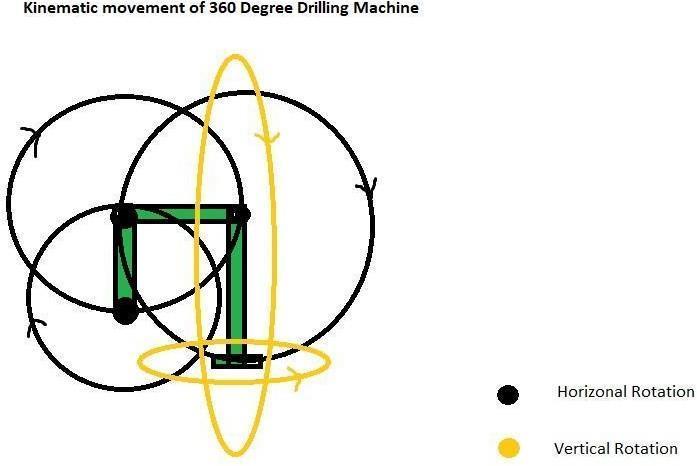
The kinematic movements of the drilling machine as shown in Fig 5. is the essential part for the proper functioning of the drill setup. This study helped us for the proper dimensions impared in the connecting arms. This makes the drill setup easier to move and the arms do not collide themselves. The diagram shows the detailed movements of the connecting arms. The black circle indicates the horizontal rotation. There are three horizontal rotations. The yellow circle indicates the verticalrotation.Therearetwoverticalrotations.Hence five rotational studies have been carried out to understand the proper movements of the 360 degree drillingmachine.
Fig5. Kinematic Movement of360 Degree DrillingMachine
6.1 STATIC STRESS
Themostprevalentformofstructuralanalysisutilizing the FE approach is static stress analysis. A component's or assembly's stress, strain, and deformation can be examined under a variety of load circumstances to ensurethatcostlyfailuresareavoidedduringthedesign stage.Typicalstructuralloadsincludeoneormoreofthe following:
7.1 Cutting Speed (V):
The rate at which the drill bit removes metal in one second. The drilling action in the workpiece is represented by the cutting speed. As a result, the mathematicalcalculationshavebeencompleted.
● Pressure loading in pressure vessels, for example,isanexampleofsurfaceloads.
The 360 Degree drilling machine analyzed using Fusion 360 Simulation Software. Various studies had to be done on the arms and the drill bits for the ultimate tensilestrengthandstressactedonthedrillingmachine. Withthehelpofanalysis,thedesignisiteratedtogetthe higher efficiency of the drilling machine.The theoretical calculationsconcludedhowthedesignoftheconnecting armsshouldbeandthesoftwareanalysisconcludedthe deformation of the setup during the drilling setup and operations.
7.2 Feed Rate (f):
F=sfn
International Research Journal of Engineering and Technology (IRJET) e ISSN: 2395 0056 Volume: 08 Issue: 12 | Dec 2021 www.irjet.net p ISSN: 2395 0072 © 2021, IRJET | Impact Factor value: 7.529 | ISO 9001:2008 Certified Journal | Page1469 drillbitisimplementedinthedesignwhichisshowninFig 4.5. Fig4.5 DesignofDrill bit 5. KINEMATIC MOVEMENT OF DRILLING MACHINE
7. THEORETICAL ANALYSIS
● Drillchuck(mildsteel)
6. ANALYSIS
● Drillbit(Highspeedsteel)
Themulti physicstechnique mayalsobeusedtosimulate thestructuralresponsetomorecomplicatedloads,suchas those resulting from thermal analysis. We did our simulation through Fusion 360.The Study is based on the fourcomponents:
● ConnectingArm1(MildSteel)
● ConnectingArmLinkage2(mildsteel)
Inches per minute, inch per bit revolution, number of bit revolutions per inch of advance, or feet per hour are the rates at which a drilling bit is advanced into or penetrates the rock formation being drilled. Forward speedisalsoknownascuttingrate.
● Forcesinthebody(gravity,accelerationsuchas centrifugalforceinrotatingmachines)
V=πDN N=1650rpmV=284.86mm/sec
● Clamping force in subsea connections is one exampleofexternalforces.
Our product's goal is to rotate 360 degrees and make it more user friendly. Our 360 degree flexible machine is smaller than previous models available on the market. As a result, getting from one place to another is relativelystraightforward.Thismachineislightweightand portable. The total amount of space needed is similarly little. We can drill holes in any direction at any moment with the help of this machine. This machine reduces manufacturing cycle time, eliminates re clamping (once theworkpieceisclampedinonedirection,thereisnoneed to re clamp in a different direction), reduces the number of machines needed, and eliminates human error. The machine is quite easy to use. It is not as hefty as we had assumed, so anyone may operate it without difficulty. It surpassesourexpectationsandperformsadmirably. The results obtained from the simulation satisfied the manufacturingcriteriaandwithstandthehighloadsatthe end of the connecting arms. This assures the different weight portable drilling machines can be clamped at the endoftheconnectingarms,Itcanwithstandtheloadupto 57(566 N) kg of weight with the addition of gravity. The whole weight acts on the rotating point of the connecting armandalsosatisfiesthemanufacturingrequirements.
8.1 DRILL BIT
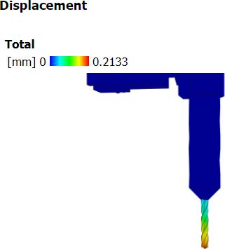
Fig8.1 Total deformation of drill bit
The main objective is to optimize to withstand the high load of the given load .In Fusion 360 simulation , this experimentation part is to be fixed with some constraints andthedrill bithasto be given a force of 200 N from top loadandthedeformationresultis0.2mmasshowninthe Fig8.1
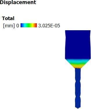
8.2 DRILL CHUCK
Themainobjectiveinthisdrillchuckistocarrythedrill bitwithhighloadsofourgivenloads.So,insimulationthe drill bit and upper part of the chuck is to be fixed with someconstraintsandtheloadactingonthesurfaceofthe chuck with the load of 250 N and the output results is getting some positive output and the deformation is 0.00325mmasshownintheFig8.2.
International Research Journal of Engineering and Technology (IRJET) e ISSN: 2395 0056 Volume: 08 Issue: 12 | Dec 2021 www.irjet.net p ISSN: 2395 0072 © 2021, IRJET | Impact Factor value: 7.529 | ISO 9001:2008 Certified Journal | Page1470 F=40mm/min. 7.3 Depth of Cut (d): Itistheentireamountof metal removedbythecutting tool in one pass. It is measured in millimeters. It varies depending on the tool and the work material. Mathematically, it is equal to half of the diameter difference. d=D/2d=1.5156 7.4 Material Removal Rate : Whenconductingmachiningoperationssuchasusinga lathe or milling machine, the material removal rate (MRR) is the amount of material removed per time unit (typically per minute). The higher the material removal rate,themorematerialremovedeachminute. MRR=(D*D/4)fN MRR=493602.75mm/min 7.5 Machining Time: Simply multiply the length of the machining motion in inchesbythefeedrateininchesperminute. LWhere,t=L/f=lengthoftheholetobedrilled =100mm f =feedofthedrill =42mm/min t =2.52min 7.6 Torque: Torque is the amount of force produced by the drill as itturnsanobject,notthespeedatwhichitturns.Torque ratings have continuously increased in recent years, far abovewhatisreallyrequiredtofulfillapplications. P=15 PN=1750watts,rpm=2 ��NT/60 T=Px60/2*N T=15x60/2x1750 T=81.8531N mm 8. RESULTS AND DISCUSSION
drilling
2. K. I. Nargatti,S. V. Patil, Design And Fabrication of Multi Spindle Drilling Head with Varying Center Distance, International Journal of Trend inResearchandDevelopment,vol 34, pp.1154 1158
4. Ms.A.A.Shingavi, Dr.A.D Dongare, Prof. S.N.Nimbalkar,2015,“DesignofMultipleSpindle Drilling Machine'', International Journal of ResearchinAdventTechnology.
1. R.Anandhan, P.Gunasekaran. 2016, “Design and Fabrication of Angular Drilling Machine”, International Journal of Innovative Research in Science, Engineering and Technology ,vol 2,pp.456 457
3. Dnyaneshwar B Bharad, Rahul D Gawande, 2017,“TwoSpindleDrillingHead”,International ResearchJournalofEngineeringandTechnology (IRJET).pp.64 89
International Research Journal of Engineering and Technology (IRJET) e ISSN: 2395 0056 Volume: 08 Issue: 12 | Dec 2021 www.irjet.net p ISSN: 2395 0072 © 2021, IRJET | Impact Factor value: 7.529 | ISO 9001:2008 Certified Journal | Page1471 Fig8.2 Total deformation of drill chuck 9. CONCLUSION This project can be counted on to run well and at a low cost.Thismachinecanexecuteawiderangeofoperations and holes. In comparison to other accessible resources, it is effective and cost effective. While taking into account the model's applications and pricing, when compared to other machines, this machine becomes reasonably priced. This allows you to operate between the drill bit and the drill bed when room is at a premium. The advantage of thisprojectareasfollows: ● DrillingEfficiency ● Flexible ● 360DegreeRotation ● SimpleToUse ● ReductionOfHandlingCost ● TimeSaving ● ReductionOfOverallManufacturingCosts ● ImprovementOfProductivity Due to the various problems faced by conventional operation processes such as Poor thread finish, more time consumption, frequent tool breakage and many more. So, we have decided to design the machine which will make use of compressed air as a power source Above is the Future model of drilling machine on which thedrillingoperationisachievedby360degreerotation system and it eliminates all the problem faced by conventional operation process. This 360 degree multi operationMachineistobepresentedforincreasingtheir productivity as well as quality of job. It also gives a detailed description of machine mechanisms and their different main parts of the machine. In this we are definingdifferentprocessparameterslikespindlespeed (rpm),cuttingfeed rate,cuttingforce,torqueandpower for their efficient working of operation. In this 360 degree drilling machine we designed and analysed our model to optimise how the connecting arm and joints can withstand and hold the drilling machine which will withstandhighloads,ultimatetensilestrengthandyield stress with the help of fusion 360 simulation. In that resultwecalculatetheoreticalandanalysedbythe static stress structural method. In that we conclude the total deformationofthematerial,Reactionforceofthepart Von misesstressofthematerialwhichgivesexactvalue ofdeformation.Sowecanachieveahighefficientdrilling machine which is going to be an alternate drilling machine for future developments. There is no vibration intheconnectingarmswhichprovidesaccurateholeson the workpiece and do not cause deformation on their drillbitswhentheheavyloadisapplied. Hencethetotal drill setup improves the productivity of the manufacturingandtimeefficient.Oncethesetupisdone, we can drill any type of drilling applications in any of axes and angles This machine does not require skilled labourersasitis easyto learnanduse which minimizes the handling stress of the operator. The addition of handle grip guides the labourer to make it more convenient.Ournextstudywillbebasedontherealtime applications of nothing but manufacturing. The analysis madeonthemanufacturingiscomparedwithsimulation phase to get the optimum results .The future study is basedontheautomatic360degreedrillingmachinewith the replacement of connecting arms as telescopic arms. Joints are replacement of Ball joints. The motion of the arm movement is based on the sensors and the Programminglogiccontroller.
5. Shin, K.G. and Mckay, N.D. (1984), “Open Loop Minimum Time Control of Mechanical ManipulationsanditsApplications‟,Proc.Amer.
10. REFERENCES
10. Prof.Ms.A.A.Shingavi, Dr.A.D Dongare, Prof. S.N.Nimbalkar,2015,”DesignofMultipleSpindle Drilling Machine'', International Journal of Research in Advent Technology, Volume 6, November2015 11. Raut Shreyank Prakash, Routela Dinesh Singh BahadurSingh,2018,“DesignandFabricationof MultiAxisDrillingMachine”,IJIRT.
International Research Journal of Engineering and Technology (IRJET) e ISSN: 2395 0056 Volume: 08 Issue: 12 | Dec 2021 www.irjet.net p ISSN: 2395 0072 © 2021, IRJET | Impact Factor value: 7.529 | ISO 9001:2008 Certified Journal | Page1472 Contr.Conf.,SanDiego,CA,pp.1231 1236. 6. Mr.SakateP.R.,Mr.JadhavA.S.,Prof.Bamankar P.B. , Miss. Jagdale A.A., Miss. Bhosale P.S. , A Review on “Multi Spindle Drilling Special Purpose Machine with Respect to Productivity”, International Journal for Scientific Research & Development,Vol.3,2015,pp.560 562 7. Mr.K.I.Nargatti,Mr.S.V.Patil,Mr.G.N.Rakate ,Design And Fabrication of Multispindle Drilling Head with Varying Centre Distance, International Journal of Trend in Research and Development, Volume 3(3) , May Jun2016,pp.506 508 8. Dnyaneshwar B Bharad, Rahul D Gawande, Pratik D Ghangale, Rahul K Gunjal, Prof.A.S.Autade, Prof.P.P.Darade, A Paper on “Two Spindle Drilling Head”, International ResearchJournalofEngineeringandTechnology ,Volume:04,Apr 2017,pp.818 821 9. S. R. Gawande, S. P. Trikal, “Development of Multi Spindle Drilling Machine” to Enhance the Productivity in Amba Stainless Steel Kitchen Trolley Manufacturer, Amravati, International Journal of Science and Research, Volume 4, October2015,pp.1659 1661
12. Ms. P.H.Dahake, “Computerized Drilling Machine, International Journal on Recent and Innovation TrendsinComputingandCommunication”. 13. V.B.Bhandari,“DesignofMachineElements”,2nd ed.,vol.1.TataMcGraw HillPublishingCompany Limited,NewDelhi. 14. Central Machine Tool Institute Bangalore, Machinetool design handbook, New Delhi: Tata McGraw Hill. 15. N. U. Kakade, Piyush Bhake, Sumit Dandekar, Rohan Kolte, Sumit Selokar, “Fabrication of Combine Drilling and Tapping Machine”, International Research Journal of Engineering and Technology (IRJET), Volume 04, Issue 03, 2017,pp.305 307.