1.2 Analysis of the Problem
are
Failure Analysis of Axle Casing of Mahindra Yuvo 575 DI 4WD.
International Research Journal of Engineering and Technology (IRJET) e ISSN: 2395 0056 Volume: 08 Issue: 12 | Dec 2021 www.irjet.net p ISSN: 2395 0072 © 2021, IRJET | Impact Factor value: 7.529 | ISO 9001:2008 Certified Journal | Page1444 Structural and Finite Element Analysis of Tractor Axle Casing Rishabh Mishra 1, Pankaj Sidar 2, Kamlesh Ratre3 1M. Tech Scholar, Department of Mechanical Engineering, VEC Ambikapur, C.G. India 2Assistant Professor, Department of Mechanical Engineering, VEC Ambikapur, C.G. India 3Assistant Professor, Department of Mechanical Engineering, VEC Ambikapur, C.G. India *** Abstract This paper describes the failure analysis of a tractor's axle casing based on a tractor's spline loaded with a trolley. The rationale behind the failure is that the weight transfer from back to front reduces, which is considered a remedial measure for failure. Key Words: Axle Casing, Ansys, Finite Element Analysis, SolidWorks, 1. INTRODUCTION
3. AXLE CASING MODELING
Duringtheforwardmovementofafront wheel drivetractor withadrawbarpull,thereisaweighttransferfromthefront wheel to the front wheel. As a result, the front wheels developpoorgroundcontactcomparedtothefrontwheels, andthetractortendstogetliftedfromthefront.Whenthe frontwheelgetslifted,thesteeringdoesnotrespondtothe operator.Suchanincidentisrisky,andthereisapossibility of an accident. The entire load of the tractor and the torsionaldrivingloadactsontheaxlecasingby liftingthe frontwheel.
Atractor,anoff roadvehicle,isanyvehiclethatcanmoveon pavedorgravelsurfaces.Theengine,gearbox,differential, andaxlecarrieraredirectlyconnectedinatractortoforma singleunit. Sincethetractor ismeantto pull a load,ithas beendesignedtodelivercomparativelyhightorqueandlow Inspeed.addition to the many critical agricultural applications, tractors have various commercial applications, such as haulageoperationsinsandmining.Inthepresentwork,the finite element analysis approach is used to replace the existing axle casing of the tractor. Premature failure that occursbeforetheexpectedloadcycleisstudiedduringthe lifeoftheaxlecasing. For example, failure of axle casings is very likely to occur duringsandminingoperations,wheresandistransported bytractorfromtheriverbankforconstructionpurposes.In thiscase,atractorisusedwithatrolleytocarrysand.During thisoperation,thetractormustoperateinextremeadverse road conditions and must pull a load of 20 to 27 tonnes
a) Themainobjectiveofthisworkistoanalyzeautomobile axlecasing.
Material Properties Table1:MaterialPropertiesofAISI1023carbonsteel Mechanical Properties Metric Tensile strength 425MPa Yield strength 282.685049MPa Shear modulus 80.0GPa Bulk modulus 140GPa Elastic modulus 204999.998MPa Poisson's ratio 0.29 Elongation at break 15% Reduction of area 40% Hardness Brinell 121 Hardness, Knoop 140 Hardness, Rockwell B 68 Hardness, Vickers 126 Machinability 65 Density 7858kg/m3 Thermal conductivity 51.9W/mK
d) Necessarydesignchangeswillbeadoptedtoattainthe axlecasing'srequiredfatiguelife.
c) To study fatigue analysis of the axle casing to find the fatiguelife.
The axle casing is one of the tractor components that presentinthe Itsprimaryfunctionisprotecting the mountedonthe tractor's
differentialandaxle.Thiscomponentis
2. MATERIAL PROPERTIES
backwheels,calledAxlecasing.
1.1 The objective of Research.
Theloadsactingontheaxlecasingis 1. Torsionalload, 2. Theself weightofthetractor. Duetotherepeatedapplicationoftheaboveloadtotheaxle casing,theaxlecasingfailsduetofatigueovera period of operationof600to1000hours.
b) Modeling axle casing using SOLID WORKS 2017 and ANSYSworkbench2019R3.
differential.

The axle casing is the outer cover of the axle. Its primary functionistoprotecttheaxle.Theaxlecasingisattachedto thecase5casesandhasaninnercircumferentialsurface,the ringgearisincludedintheplanetaryreductionmechanism, theringgearaxlecasingismountedontheinnerperipheral surfaceofthecase.
4. FINITE ELEMENT MODEL
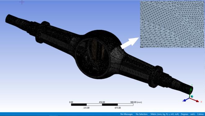
AsshowninFig3,afull scaledCADmodelofthecasingwas preparedfortheanalyses.Thecasingessentiallyconsistsof two identical thin walledshells,9.5 mm thick and welded along the neutral axis of the spindle. A mounting ring is welded to the casing assembly to increase rigidity on the front side, and the differential carrier is bolted on it. For sealingreasons,adomeisweldedtothefrontside.
5. FINITE ELEMENT ANALYSIS AND RESULTS
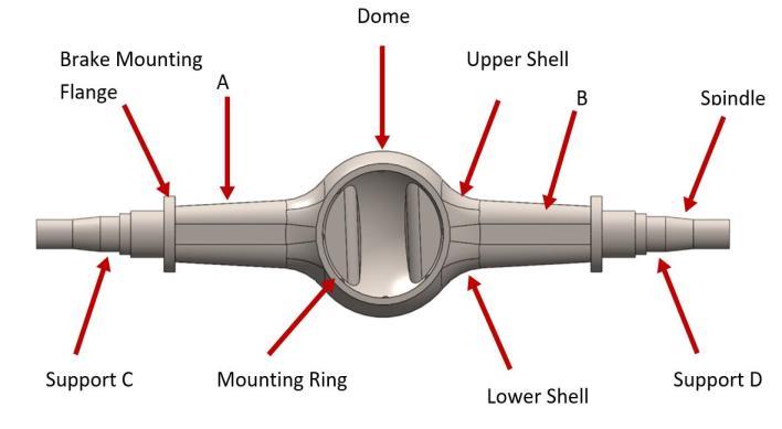
The finite element model casing was meshed using SOLID187,ahigher orderthree dimensionalsolidelement withaquadraticdisplacementbehaviorandiswellsuitedto irregularmodelmeshes.Theelementisdefinedbytennodes havingthreetranslationalDOFateachnode.Theelements CONTA174andTARGE170wereusedtomodelthecontact betweenthestructuralpartsofthecasing.Thefullybonded contactwaschosenasthecontactconditionforallwelded surfaces. The FE model included 779,305 elements and 1,287,354nodes.
FE analysis was used to estimate the precise location of regionswheretensilestressconcentrationswereobserved, andthefatiguelifeisrelativelyshort.
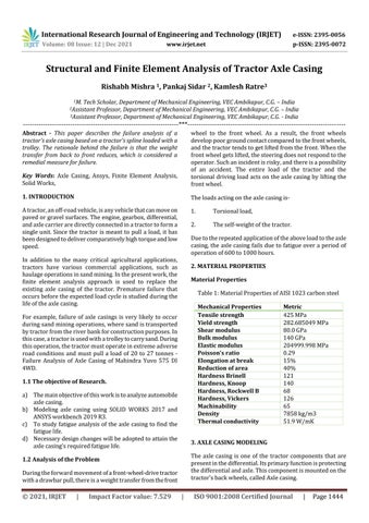
Here, elements A and B represent trailing arm caliper connections.Here,elementsAandBrepresentthetrailing arm caliperconnection.SupportsCandDstandforwheeled road contacts. The distance between the support casing contactpointsisequaltothatofthewheeltrackoftheaxle. ThesolidmodelofthecasingwascomposedviaSolidWorks 2017.CADmodelofthecompletecasingwasimportedinto ANSYSWorkbench2019R3preprocessingenvironmentto constitutetheFEmodelrequiredintheanalyses.
Figure 1. SchematicDiagramofaxlecasing 3.1 Node and Element Loads: Loadingis defined in two ways:NodeandElement.Nodal loadsaredefined on nodes andare not directlyrelated to elements. These nodals are linked to the DoF at the load node. Elemental weight is surface load, body weight and inertialload.Someelementscanevenhave"flags".Flagsare notloadedbutindicatethataparticularcalculationistobe performed.
International Research Journal of Engineering and Technology (IRJET) e ISSN: 2395 0056 Volume: 08 Issue: 05 | May 2021 www.irjet.net p ISSN: 2395 0072 © 2021, IRJET | Impact Factor value: 7.529 | ISO 9001:2008 Certified Journal | Page1445
Figure 2. Meshingofaxlecasingmodel
Figure 3. FiniteElementModel
Then the node pattern becomes I, J, K, K. If L node is not input,itdefaultstonodeK.Ifadditionalsizefunctionsare includedintheelement,theyareautomaticallysuppressed (theelementisrenumberedtoalowerorder).Thespecified element load on a nodal basis should have the same load specifiedattheexactnodelocations.
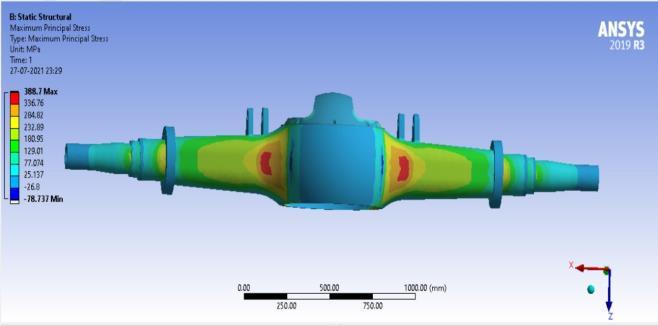
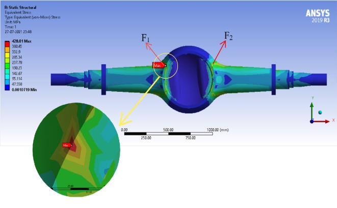
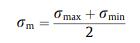
AnalysiswascarriedoutusingANSYSWorkbench2019R3. Fig.5showstheequivalentvonMisesstressdistributionof the FE analysis. Locations of the critical regions and the prematurefatiguefailurearethesameasseeninFig.5.The calculatedmaximumvonMisesstressisσmax =388.7MPa; 78.1%oftheyieldingpointofmaterial.Thismeansthatthe casingprototypesatisfiesthesafetyconditionsformaximum loadingifitisexertedstatically. Figure 4. MaximumPrincipalStress Figure 5. Von MissesStress 6. FATIGUE LIFE PREDICTION Tfatigueanalysiswasalsoperformedsincetheaxlecasingis loadedwithdynamicforcesduringservice Anestimationof thestresslifeendurancelimitSe isgivenas S’e =0.504Sut Theultimatestrength(Sut) ofsteelislessthan1400MPa.It represents fatigue strength at 106 cycles and more. To predict part fatiguelifeinthe rangeof 105 106 cycles, the casing material's S N curve was estimated through a practicalmethodthatusesdataobtainedfromsimpletensile Totests.predict the true fatigue strength Se for a mechanical component, Se must be multiplied by several modifying factors representing various design, manufacturing, and environmentalinfluencesonthefatiguestrength. Se isgivenas Se = kb S’e ka kd kc ke
For non rounded sections, the shape factor kb can be considered as 0.75 for values of the depth of the cross sectionhthatexceed50mm.Loadfactorkc isgivenas1for bending, and temperature factor kd is 1 for the ambient temperaturerangeofT=0 250 oC.
ThroughstaticFEanalysis,itisobservedthatthebanjoand arm are stress focused regions at the transition zones. Therefore,inadditiontothemodifyingfactorsmentioned,a fatiguestrengthmodifyingfactorke mustbeconsideredby means of the static stress concentration factor Kt that is relatedtofatiguestressconcentrationfactorKf.Hencekeis calculatedas ke =1/Kf For safety reasons, Kf can be assumed to be equal to Kt Because of the dimensions and shape complexity of the casing, Kt cannot be derived from data in the standard literature.Kt isdefinedas whereσpeak =peakstress, σnominal=nominalstresspresentifastressconcentrationdid notoccur.σpeak wasusedasthevalueobtainedfromstatic finiteelementanalyses, σpeak =σmax =388.7MPa.
σnominal =M/Z whereM=bendingmomentandZ=sectionmodulusofthe criticalcross section.
Sincetheroughnessoftheshellsurfacesissimilartothehot rolledsheetafterhotstamping,recommendedvaluesare a=57.7andb=0.718 ka =0.56forSut =629.89MPa.
Inaddition,shotpeening,awell knownprocesstointroduce favorable residual stresses in the material surface of a component,isalsoappliedonthecasingsurfacesafterhot stampingtoincreasethefatiguelifeofthepart.Inliterature, thisincreaseisgivenbysomeas70%.Henceka=0.959forn thefatigueanalysis.
International Research Journal of Engineering and Technology (IRJET) e ISSN: 2395 0056 Volume: 08 Issue: 05 | May 2021 www.irjet.net p ISSN: 2395 0072 © 2021, IRJET | Impact Factor value: 7.529 | ISO 9001:2008 Certified Journal | Page1446
Tocalculateσnominal,theaxlewasassumedasasimplebeam whichhasauniformboxprofilecross sectionX1 X1 ofthe criticalregionalongthelongitudinalaxisYandsubjectedto purebending.

Asanalternative,thetransitiongeometrycanberedesigned.
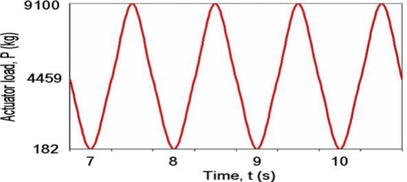
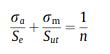
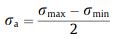
International Research Journal of Engineering and Technology (IRJET) e ISSN: 2395 0056 Volume: 08 Issue: 05 | May 2021 www.irjet.net p ISSN: 2395 0072 © 2021, IRJET | Impact Factor value: 7.529 | ISO 9001:2008 Certified Journal | Page1447 M was obtained as 41.9 x 10⁶ N mm. Section modulus (Z) wascalculated,Z=127500mm3andthusσnominal=329MPa. Kt ~Kf =1.181andke =0.846. TheS Ncurveplottedregardingthemodifyingfactorswas defined in the ANSYS Workbench 2019 R3 user interface. Thestress lifeapproachwasusedtodeterminethefatigue lifeofthecasingmaterial.VonMisesstressesweobtained from finite element analyses are utilized in fatigue life calculations.Sincetheloadinghasa sinusoidal fluctuating characteristic (mean stress, σm > 0), modified Goodman approachgivenas Herenstandsforthefactorofsafety. Stressamplitudeσa isgivenas andthemeanstressσm canbeexpressedas Here,bothσmaxcorrespondingtoamaximumof9100kgand σmin matching a minimum of 182 kg of vertical load were obtainedviaFEanalysis. ThedistributionofnatthelowershellcanbeseeninFig.4
FE analysis showed that the regions where fatigue failure was initiated during vertical fatigue tests are subject to stressconcentration,leadingtoprematurefailurepastthe estimated 5 x 10⁵ minimum cycle limit. The results agree withtheresultsoftheverticalfatiguetests.
d) σmax wascomputedas,σmax =388.7MPa
b) Desiredminimumloadcyclesof5x105 c) σnominalwascomputedas329MPa
Anincreaseinthefatiguelifeofthecasingisdependentona decrease in the stress concentration. However, except in areasF1andF2,thecovermeetstheinfinitelifecriterion.An increase in the thickness of the sheet metal leads to an unnecessary increase in weight. For example, a thickness increaseof0.5mmincreasesthefatiguelimitofthecasing materialto5.8×105 cyclesincriticalareasthatexceedthe desired limit. On the other hand, it also means that the weightincreasesbyabout5%ofthemassofthevehicle.
Smooth transition geometry can increase fatigue without addingweight.Inaddition,theshapeofthereinforcement ring also affects the stress concentration. In the studied design, the thickness of the ring is 20 mm. Finite element analysiswasrepeatedforthecasewithouttheringtopredict theeffectsofthering.
Figure 6 GraphbetweenStressAmplitudeandNumberof CycletoFailure RESULTS AND DISCUSSION
7.
a) MaximumvonMisesstresswasobtainedas428.01 MPa
MaximumvonMisesstresswasobtainedas428.01MPaat the critical region F2. This means the use of the ring decreasesstressconcentrationbyabout10%.Byincreasing thethicknessofthe part,itispossibletoobtainenhanced rigidity. In this design, due to the drivetrain limit configuration,thisincreasedto5mm.Thestaticandfatigue analysis was composed according to this change in ring shape.However,analyzesrevealedthatthisincreaseinitself somewhatprolongsthefatiguelifeofthecasing,whichisnot sufficienttoachievethedesiredminimumloadcycleof5x 105. Therefore, ring thickness enhancement can be implementedwitharedesignofthetransitiongeometry.
The fatigue analysis results was estimated that crack initiation could occur at the region F1 of the outer shell surfaceat3.6x105 cycles,whichislowerthantheexpected minimumfatiguelifeof5x105 cycles.
7.1 Concluding Remarks
Premature fatigue failure of an axle casing prototype was examinedusingfiniteelementanalysis.Inanalyzesinwhich the vertical fatigue test procedure was simulated, stress focusedareaswerepredictedinthebanjotransitionzone. Theareaswherefatiguecracksoccurredwerewellmatched withtheanalysisresults. Using FE analysis, the location of the failure can be estimated.Thedeterminedcriticalregionsaresubjectedtoa combinedstaticandcyclictensilestress.Thecrackcausing fractureisinitiatedatthestress concentratedregionsofthe casing. Although the casing prototype satisfies the static enduranceconditionformaximumverticalload,analysishas shownthatprematurefatiguefailurecanoccurifthisloadis appliedcyclicallypasttheestimated5x105minimumcycle Tolimit.solvetheproblem,increasingsheetmetalthicknessisnot a practical solution because of the weight increase of the casing. An application including redesigning the banjo transition area and increasing the reinforcement ring thickness may be an excellent option to achieve longer fatiguelife,whichcanmeetminimumdesigncriteria.
REFERENCES
International Research Journal of Engineering and Technology (IRJET) e ISSN: 2395 0056 Volume: 08 Issue: 05 | May 2021 www.irjet.net p ISSN: 2395 0072 © 2021, IRJET | Impact Factor value: 7.529 | ISO 9001:2008 Certified Journal | Page1448
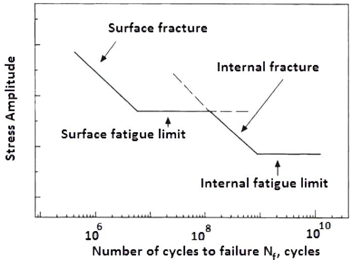
Modifiedgoodmanplotofmeanstressand stressamplitude Plotting of Stress amplitude and Mean Stress on Modified GoodmanDiagramshowsthatthemaximumstresspointis insidethesaferegion.So,AxlecasingissafeinbothFatigue and AnyYield.comparisonofmaterialsandtheirprocessingtomake thefinalproductmustbejustifiedbycomparingtheresults ofthematerialanditsprocessunderconsideration.Inthe presentwork,comparative evaluationisdone,andresults are obtained from the finite element analysis for both existingandmodifiedaxlecasing.
[7]. Design and Analysis of a Chassis Term on/Designhttps://www.termpaperwarehouse.com/essayPaper.AndAnalysisOfAChassis/398364
[9]. JournalandE.Technologies,"AnalysisofAxleTube andBrakeCasingof65HpTractor,"vol.5,no.11, pp.11 17,2017. [10]. Gaur,S.Jain,andA.Khaira,"DesignandAnalysisof ModifiedTrumpetAxle,"no.11,pp.1 3,2019. [11]. O. F. Resource, "MODELLING AND STRUCTURAL ANALYSISOFREARPageNo:295,"vol.12,no.294, pp.294 302,2021. [12]. R. Alfaro, I. Arana, S. Arazuri, and C. Jarén, "Assessing the safety provided by SAE J2194 Standard and Code 4 Standard code for testing ROPS,usingfiniteelementanalysis,"Biosyst.Eng., vol. 105, no. 2, pp. 189 197, 2010, doi: 10.1016/j.biosystemseng.2009.10.007. [13]. Firat,"Acomputersimulationoffour pointbending fatigueofarearaxleassembly,"Eng.Fail.Anal.,vol. 18, no. 8, pp. 2137 2148, 2011, doi: 10.1016/j.engfailanal.2011.07.005. [14]. M. Topaç, H. Günal, and N. S. Kuralay, "Fatigue failurepredictionofarearaxlecasingprototypeby usingfiniteelementanalysis,"Eng.Fail.Anal.,vol. 16, no. 5, pp. 1474 1482, 2009, doi: 10.1016/j.engfailanal.2008.09.016. [15]. Qinghua,Z.Huifeng,andL.Fengjun,"Fatiguefailure faultpredictionoftruckrearaxlecasingexcitedby randomroadroughness,"Int.J.Phys.Sci.,vol.6,no. 7,pp.1563 1568,2011,doi:10.5897/IJPS11.088.
Figure 7
[8]. Design and Analysis of a Chassis Term on/Designhttps://www.termpaperwarehouse.com/essayPaper.AndAnalysisOfAChassis/398364
[6]. F.HuandW.H.Liu,"Finiteelementanalysisofthe tractor front axle casing based on ANSYS," Appl. Mech.Mater.,vol.105 107,pp.168 171,2012,doi: 10.4028/www.scientific.net/AMM.105 107.168.
[1]. A.K.PandP.Aswathy,"5IVApril2017,"no.April 2017. [2]. A. Kurniawan and Andoko, "Stress and Crack SimulationonAxleCasingMitsubishiL300Pickup Car using Finite Element Method," IOP Conf. Ser. Mater.Sci.Eng.,vol.494,no.1, [3]. A. Sciences and I. No, "Optimization of Tractor TrolleyAxleforReducingtheWeightandCostUsing Finite Element Method," vol. 2, no. 3, pp. 31 35, 2013. [4]. AISI 1023 Carbon Steel (UNS 4https://www.azom.com/article.aspx?ArticleID=652G10230).
[5]. Bapi Biswas and Pankaj Sidar, "Parametric stress analysisofhelicalgearusingfea,"pp.1030 1034, V6I9153.pdf2019.https://www.irjet.net/archives/V6/i9/IRJET
International Research Journal of Engineering and Technology (IRJET) e ISSN: 2395 0056 Volume: 08 Issue: 05 | May 2021 www.irjet.net p ISSN: 2395 0072 © 2021, IRJET | Impact Factor value: 7.529 | ISO 9001:2008 Certified Journal | Page1449 [16]. M. Meyer, "Effects of Mean Stress and Stress ConcentrationonFatigueBehaviorofDuctileIron," no.December2014. [17]. S.AloniandS.Khedkar,"ComparativeEvaluationof Tractor Trolley Axle by Using Finite Element AnalysisApproach,"Int.J.Eng.Sci.Technol.,vol.4, no.4,pp.1351 1360,2012. [18]. S.ShelkeandP.Kosbe,"FailureAnalysisofBearing Cup,"vol.3,no.6,pp.13634 13641,2014. [19]. Shivaji Nilkanth, Idris Poonawala, and Milind Ramgir,"DesignOptimisationofFourWheelDrive TractorFrontAxleCasing,"Int.J.Eng.Res.,vol.V4, no.08,2015,doi:10.17577/ijertv4is080114. [20]. V. R. Kashid and A. M. Mane, "Finite element analysisandoptimizationoftractortrolleyAXLE," Int.J.Mech.Eng.Technol.,vol.7,no.4,pp.48 60, 2016. [21]. X.Shao,Z.Song,Y.Yin,B.Xie,andP.Liao,"Statistical distributionmodellingandparameteridentification of the dynamic stress spectrum of a tractor front driven axle," Biosyst. Eng., vol. 205, pp. 152 163, 2021,doi:10.1016/j.biosystemseng.2021.03.003.