RAM MISHRA1 1
Diagonal membrane from the diagrid conveys both shear and second. So the ideal point of putting the diagonals is reliantuponbuildingstature.Theidealpointofthesegments
COLLEGE
Analysis of a Tall Structure ANANT Student of M.Tech, Department of Civil Engineerin, SAM OF ENGINEERING
International Research Journal of Engineering and Technology (IRJET) e ISSN: 2395 0056 Volume: 08 Issue: 12 | Dec 2021 www.irjet.net p ISSN: 2395 0072 © 2021, IRJET | Impact Factor value: 7.529 | ISO 9001:2008 Certified Journal | Page1408 Seismic
Considering Diagrid and Tuned Dampers using ETABS
1.3 Diagrid Structural System Node Design
Thediagridunderlyingframeworkcanbecharacterizedasa corner to corner part shaped as a system made by the crossingpointofvariousmaterialslikemetals,concreteor wooden pillars which are utilized in the development of structures and rooftops. Diagrid designs of the steel individualsareproficientingivingarrangementsbothasfar asstrengthandsolidness.Yet,thesedaysafar reachinguse of diagrid is utilized in the enormous range and elevated structures, especially when they are complex calculations andbentshapes.
1.INTRODUCTION
The quick development of the metropolitan populace and subsequent tension on restricted space has impressively impactedtheprivateadvancementofthecity.Thesignificant expense of land, the craving to stay away from ceaseless endless suburbia, and the need to protect significant horticultural creation have all added to private structures up. As the stature of a structure expands, the lateral load opposingframeworkturnsouttobeahigherprioritythan the underlying framework that opposes the gravitational burdens.Thehorizontalburdenopposingframeworksthat aregenerallyutilizedaretheinflexibleedge,sheardivider, divider outline, propped tube framework, outrigger frameworkandroundedframework.Asoflate,thediagrid DiagonalGrid theprimaryframeworkisgenerallyutilized fortallsteelstructuresbecauseofitsunderlyingproductivity andstylishpotentialgivenbythenovelmathematicaldesign oftheframework.Diagridhasadecentappearanceanditis handilyperceived.Thedesignandeffectivenessofadiagrid frameworkdiminishthequantityofunderlyingcomponents neededonthefaçadeofthestructures,thuslylesscheckto theexternalview.
The present study is an effort towards analysis of the structure located on a flat ground during the earthquake. An ordinary moment resisting building of G+19 story’s located over a medium soil is considered. Comparative analysis is presented for a conventional structure with and without dampers against reaction of diagrid structure with and without damper. The number of bays will be kept as 6 along both direction and the bay size will be kept as 4m with the story height being 3m. The building will be analysed considering zone III by static equilibrium method using ETABS 2015 software. The aim of the study is to evaluate the response of a diagrid and damper system arrangement, to determine seismic parameters that are time period, modes of vibration, base shear, story displacement, story drift and story stiffness, to determine the effectiveness of combination of dampers and diagrids in comparison to conventional structure.
1.2 Module Geometry of Diagrid Structural System
AND TECHNOLOGY, BHOPAL, (M.P), India *** ● Abstract
1.1Diagrid structures
The hubs are a significant piece of the plan of the diagrid framework. Every one of the corner to corner areas are associated with one another with the assistance of hubs. Thesehubsareintendedfortwosortsofburdens,vertical burdenandevenshear.Thesehubsarejoinedtodifferent areasbyweldingorshooting.Itisensuredthatexceptionally lessmeasureoftheweldistobeutilizedinthejoining.The upwardburdenismovedaspivotalburdensfromthediagrid individualsthataresetoverthehubstothegussetplateand stiffeners, then, at that point to the diagrid individuals beneaththehubs.Thelevelshearisadditionallyaspivotal burdensinthediagridoverthehubs,howeverhereoneisin pressureandanotherisinstrain.Theexchangeofburdenis fromoverthehubparttothegussetplateandstiffenerand afterwards from the gusset plate and stiffener to the individuals beneath the hub in a couple of pressure and strain. Because of this heap move way, the shear powers createdattheareaoftheboltassociationareexceptionally high under the hour of sidelong loads. This might be the shear zone or feeble zone of this construction during the seismictremors,theplanningoftheboltassociationsistobe donecautiously.
2. Literature Review
forgreatesttwistinginflexibilityinthetypicalstructureis90 degreesandforthediagonalsforshear,unbendingnatureis 35degrees.Itisexpectedthattheidealpointofthediagrid fallsinthemiddleoftheboth.Typically,thereceivedreachis 60 70degrees.Asthestatureofthestructureexpandsthe idealpointadditionallyincrements.
Saman Sadeghi and Fayaz R. Rofooei,(2020) the paper explored that respect, the impacts of BRBs on the seismic execution qualities of diagrids, for example, reaction alteration factor, R, overstrength factor, Ω0, pliability proportion, μ, and middle breakdown limit, ^ SCT, are

Rai & Rashmi Sakalle,(2017) in the given explorationtheycontributedthatthesteeldiagridstructure atanexternal bitofthestructureat60degreeshaving an internal centre of R.C.C segments with R.C.C shaft and the section was dissected and contrasted and a regular substantial structure. The inclining individual from the diagridstructuremovedthesidelongloadsbyhubactivity contrasted with the bending of vertical segments in the regular structure framework. A normal eleven story RCC workingwithanarrangementsizeof16m×16msituatedin seismic zone V and III are considered for investigation. STAAD.Pro programming is utilized for displaying and investigationofprimary.Theseismiczonewasconsidered accordingtoIS1893.
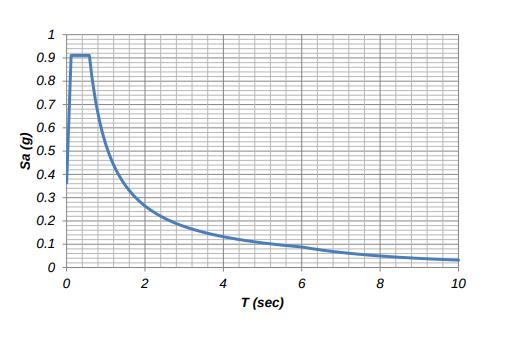
3. Problem Statement 3.1 Building Geometry Table3.1GeometryoftheStructure BuildingType Commercial PlanArea 45x45m No.ofStory G+19 HeightofStory 3m CoreThickness 400mm Angleofdiagrid 67.4° Sizeofcolumns: 500mmX500mm Sizeofbeams 300mmX500mm Thicknessofslab 120mm SizeofDiagonals: 300X500 Size of steel square tube section used for Diagrid 385.6mm X 385.6mmX11mm SupportType Fixed 3.2 Loading Condition AllloadingaredoneinaccordancetoIndianStandards. LoadCombination 1)1.5(DL+LL) 2)1.2(DL+LL±EL) 3)1.5(DL±EL) 4)0.9DL±1.5EL Liveload 4kN/m2asperIS 875(Part2) SeismicLoad Table3.3SeismicLoad ZoneFactor 0.16(III) 51.5 SoilType III Fig3.4SeismicCapacity 3.3 Structural Analysis The following are preliminary analyses to identify the behavioroftheprototypediagridbuildinganddetermineif thebuildingisadequateasabasicinputofthisstudy.
International Research Journal of Engineering and Technology (IRJET) e ISSN: 2395 0056 Volume: 08 Issue: 12 | Dec 2021 www.irjet.net p ISSN: 2395 0072 © 2021, IRJET | Impact Factor value: 7.529 | ISO 9001:2008 Certified Journal | Page1409 assessed.Tothisend,6threedimensionaldiagridstructures with different statures and inclining points are displayed utilizingtheOpenSeesprogramandarefurnishedwithBRBs inanoriginalgameplan.Usingnonlinearstaticinvestigation, the seismic presentation components of models are assessed.Inthisway,themiddlebreakdownlimit(^SCT)of themodelsaredictatedbyperformingnonlinearpowerful Bhavaniinvestigations.Shankar and Priyanka M V (2018), the new investigation examination was made on concrete diagrid buildingandordinarystructureofcomparativearrangement size (15x15)m and the investigation was made on the reactionoftheconstructionbydifferingthestoryrangefrom G+5 to G+15. Another examination was completed for diagrid and traditional constructions of comparative arrangementsize(18x18)mwithsamestorystatureG+15, andtheimpactofpointofdiagridandlengthofdiagridwas contemplated and was contrasted and the customary Avnishframework.Kumar
over
without
Planfollowsdimension 20mx20m Numberofstories G+19 Floortofloorheight 3m NumberofbaysinX direction 9 NumberofbaysinY direction 9 Depthofslab 150mm. 4.2Modelling
dampers
considering
The present study an effort towards analysis of flatgroundduring ordinarymomentresistingbuildingofG+19story’slocated a soilisconsidered. Comparative analysisis for a conventional structure with and without against reaction of diagrid structure with and damper.Thenumberofbayswillbekeptas6along bothdirectionandthebaysizewillbekeptas4mwiththe story height being 3m. The building will be analysed zone III by static equilibrium method using 2015 software. The details of models are given as
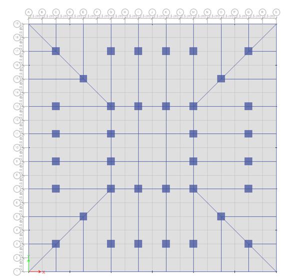
Step 1: ETABS provide an eco system to model structure usingdifferentgridsasperplan
.Fig4.1GridDesigningofthedifferentcases.
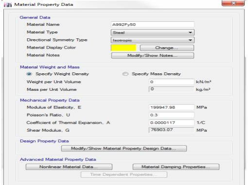
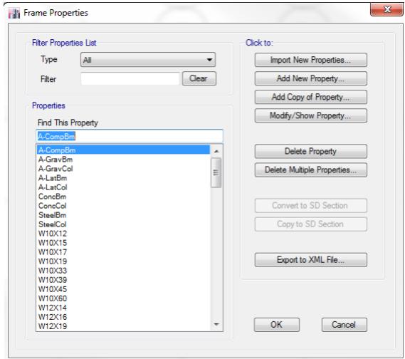
Step 2: This step includes defining material and section propertiesofbeamsandcolumnasperthegeometryofthe structurewhichwaspreviouslydescribedinchapterabove.
International Research Journal of Engineering and Technology (IRJET) e ISSN: 2395 0056 Volume: 08 Issue: 12 | Dec 2021 www.irjet.net p ISSN: 2395 0072 © 2021, IRJET | Impact Factor value: 7.529 | ISO 9001:2008 Certified Journal | Page1410 3.4.1NaturalPeriodandModeShapesoftheStructure Tofulfilltherequirementsof90%massparticipationratios, 24 modes are used for the basic diagrid model while 48 modes are used for the diagrid model with TD units. The latterhasmoremodesduetoadditionalmodesgeneratedby TD. Figure 3.5 shows the four modes of interest that characterizethebuildingbehaviorunderearthquakeevents. Those modes are holding the biggest percentage of mass participation factors on each major direction except UZ (verticaldirection).Table3.1showsthefirstsevenvibration periods of the building with their respective modal participation factors that represent the four main mode shapesofthebuilding.Thetotalmassparticipationratiosfor eachdirectionsoftheprototypebuildingmodelaccounting forthe24modesare: UX=95.87%>90% •UY=96.03%>90% •UZ=86.68% •RX=99.96%>90% •RY=99.95%>90% •RZ=94.29%>90% 4 4.1MethodologyGeneral
FigDefiningMaterialProperties FigDefiningSectionProperties
is
medium
theearthquake.An
ETABS
the structurelocatedona
presented
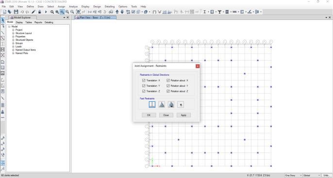
p 3: Fixed support are provided at the bottom of the structure
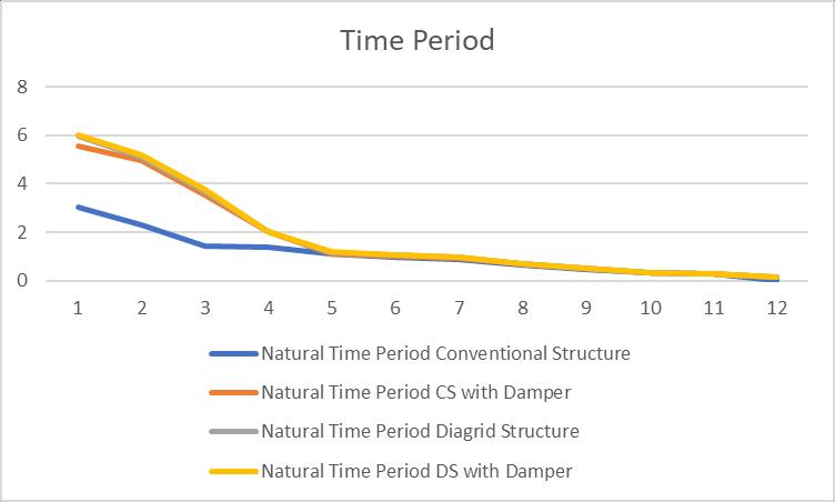
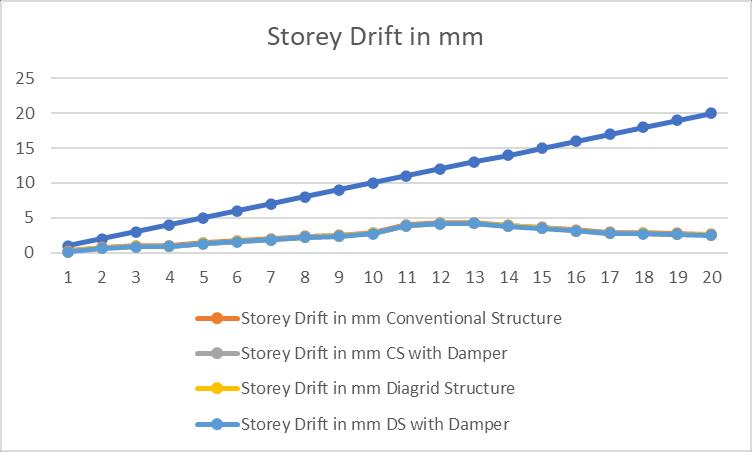
International Research Journal of Engineering and Technology (IRJET) e ISSN: 2395 0056 Volume: 08 Issue: 12 | Dec 2021 www.irjet.net p ISSN: 2395 0072 © 2021, IRJET | Impact Factor value: 7.529 | ISO 9001:2008 Certified Journal | Page1411 FigAssigningFixedSupportinX,YandZdirection. Step4DefiningLoadcondition Step5:Analyzingtheresults 5. Results and Discussion 5.1 Time Period Thenaturalperiod(Tn)ofabuildingisthetimeittakestogo through a complete vibration cycle. This is the inherent nature of the building controlled by its mass “m” and stiffness “k”. These three astrological signs are Tninterconnected.=2 ��√m/k Itsunitissecond.Buildingsthatareheavyandflexiblehave morenaturalperiodthanlightandstiffbuildings. Table5.1NaturalTimePeriodinsecond StoryDriftinmm Story StructureConventional CS Damperwith StructureDiagrid DS Dampwither 1 0.243 0.158 0.138 0.111 2 0.793 0.708 0.688 0.661 3 0.992 0.907 0.887 0.86 4 1.021 0.936 0.916 0.889 5 1.443 1.358 1.338 1.311 6 1.721 1.636 1.616 1.589 7 1.982 1.897 1.877 1.85 8 2.345 2.26 2.24 2.213 9 2.509 2.424 2.404 2.377 10 2.876 2.791 2.771 2.744 11 3.987 3.902 3.882 3.855 12 4.284 4.199 4.179 4.152 13 4.321 4.236 4.216 4.189 14 3.943 3.858 3.838 3.811 15 3.667 3.582 3.562 3.535 16 3.261 3.176 3.156 3.129 17 2.908 2.823 2.803 2.776 18 2.867 2.782 2.762 2.735 19 2.76 2.675 2.655 2.628 20 2.6409 2.5559 2.5359 2.5089 Fig5.1FundamentalTimePeriod 5.2 Story Drift Itisthedisplacementofonestoryrelativetotheotherstory above or below. The story drift in any story due to the minimum specified design lateral force, with partial load factorof1,shallnotexceed0.004timesthestoryheightor In(h/250).Eurocode 8:2004 Part 1 specifies allowable maximum storydriftis1%ofstoryheightthereforeasperEurocode permissiblelimitofdriftwillbe0.01X3000=30mm. Table5.2StoreyDriftinmm Fig5.2StoryDriftinmm
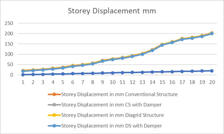
International Research Journal of Engineering and Technology (IRJET) e ISSN: 2395 0056 Volume: 08 Issue: 12 | Dec 2021 www.irjet.net p ISSN: 2395 0072 © 2021, IRJET | Impact Factor value: 7.529 | ISO 9001:2008 Certified Journal | Page1412 5.3 Story Displacement Itistotaldisplacementofthestorywithrespecttoground. According to IS 1893:2016 Clause deformations, the maximumallowabledeflectioniscalculatedasH/250,where h is the height of the story from the ground level. In Eurocode 8:2004 specifies allowable maximum story displacementisH/100. StoryDisplacementinmm Story StructureConventional CS Damperwith StructureDiagrid DS Damperwith 1 21.3421 19.0211 20.2552 17.9998 2 24.5347 22.2137 23.4478 21.1924 3 27.438 25.117 26.3511 24.0957 4 31.7934 29.4724 30.7065 28.4511 5 36.9834 34.6624 35.8965 33.6411 6 44.7995 42.4785 43.7126 41.4572 7 49.9792 47.6582 48.8923 46.6369 8 56.782 54.461 55.6951 53.4397 9 69.9237 67.6027 68.8368 66.5814 10 77.5893 75.2683 76.5024 74.247 11 83.9832 81.6622 82.8963 80.6409 12 92.743 90.422 91.6561 89.4007 13 103.247 100.926 102.1601 99.9047 14 121.567 119.246 120.4801 118.2247 15 147.823 145.502 146.7361 144.4807 16 159.869 157.548 158.7821 156.5267 17 175.389 173.068 174.3021 172.0467 18 181.295 178.974 180.2081 177.9527 19 189.823 187.502 188.7361 186.4807 20 203.211 200.89 202.1241 199.8687 5.4 Base Shear IS 1893:2016 (Part I) Auto Seismic Load Calculation: This calculation presents the automatically generated lateral seismicloadsforloadpatternEQ XandEQ YaccordingtoIS Where,Vb1893:2016.=AhxWAh= Design horizontal seismic coefficient for W=structureSeismicweightofthebuilding. Where,R=responsereductionfactor. Z=zonefactor. I=importancefactor. Sa/g=averageaccelerationresponsecoefficient. Model BaseShear(kN) StructureConventional 2103.8416 CS with Damper 2523.47 StructureDiagrid 2520.6485 DS with Damper 2212.462 5.5 Story Stiffness The term story stiffness is defined as the capability of resisting force/load acting on any story. It depends on materialproperty,ifthestoryisstifferitmeanslessflexible. StoryStiffness Story lConventionaStructure CS Damperwith StructureDiagrid DS Damperwith 1 23603161.1 1192357 23603049.1 989255.573 2 13288034.4 1100669 13287922.4 911726.623 3 9522210.36 1012978 9522098.36 880606.49 4 7504235.74 982994 7504123.74 847875.789 5 5324383.12 953670 5324271.12 813968.332 6 4430231.54 925661 4430119.54 785484.175 7 3798684.67 897729 3798572.67 755676.824 8 3341982.9 869698 3341870.9 727736.724 9 3089083.22 841696 3088971.22 701896.915 10 2716899.78 814024 2716787.78 677241.584
Itconcludesthatthenodedisplacementdecreases in both diagrid buildings i.e with and without flat slab whilst examined with conational kind of building.
REFERENCES
3.)SunilGurdekarandMayurSingi,[DynamicAnalysisofFlat Slab Diagrid Structure with Response Spectrum Method],MuktShabdJournal2020.
It’sfoundthatthetotalbasesheardecreases5%in diagrid building with conventional slab and decreases 15% in flat slab diagrid Building while comparing with traditional building for seismic analysis.
International Research Journal of Engineering and Technology (IRJET) e ISSN: 2395 0056 Volume: 08 Issue: 12 | Dec 2021 www.irjet.net p ISSN: 2395 0072 © 2021, IRJET | Impact Factor value: 7.529 | ISO 9001:2008 Certified Journal | Page1413 11 2430767.13 787047 2430655.13 653650.96 12 2233971.77 761102 2233859.77 630998.566 13 1866556.25 736439 1866444.25 609273.233 14 1634992.38 713176 1634880.38 588471.647 15 1453101.15 691306 1452989.15 568593.547 16 1357240.11 670728 1357128.11 549627.73 17 1327421.21 651296 1327309.21 531555.69 18 1221694.59 632868 1221582.59 514357.33 19 1122616.59 615337 1122504.59 498017.136 20 1077312.9 598642 1077200.9 482526.738 6. Conclusion and Future Scope 6.1 Conclusion thecarriedwithofeffectivebehaviorResponsespectrumanalysisresultsprovidesamorerealisticofstructureresponseanddiagridstructureismoreinlateralloadresistanceSeismicandwindanalysisconventionalbuildingwithTMDanddiagridstructureTMDwithequivalentplanareaatseismiczoneIIIisoutandthefollowingconclusionsaredrawnfromstudy:
1. In this study we are considering tall structure whereas stability in low height of mid rise structures can be justify in future with same conditions.
● MaximumCentreshearstressesinslabSQXandSQY areincreasedindiagridbuildingswithflatslabas compared to conventional building and diagrid buildingwithoutflatslab.
Total base shear increases in the circular form of diagrid constructing and decreases in square and triangular form of diagrid constructing while comparingwithtraditionalconstructingforseismic analysis.
● Maximumbendingmomentatthemiddleoftheslab i.e. MX, MY & MXY more growth in diagrid constructionasexaminedtostandardconstruction.
● The values of story drift are found to be within permissiblelimiti.e.notmorethan0.004timesthe story height as per norms according to IS 1893:2002(Part 1)forseismicanalysis.
2. Inthisstudyseismicloadingisconsideredwhereas infuturewindloadorthermalloadcanbeutilize.
5.) Ravish Khan and S.B. Shinde,[ANALYSIS OF DIAGRID STRUCTURE IN COMPARISON WITH EXTERIOR BRACED FRAME STRUCTURE],International Journal of Research in EngineeringandTechnology,2015 6.) Garlan Ramadhan and André R. Barbosa,[IMPROVING THE SEISMIC PERFORMANCE OF DIAGRID STEEL STRUCTURES USING FRICTION MASS DAMPER], National Conference in Earthquake Engineering, Earthquake EngineeringResearchInstitute,Anchorage,AK,2014.
●
1.) Andre R. Barbosa and Garlan Ramadhan,[Seismic Performance of a Tall Diagrid Steel Building with Tuned MassDampers],2014EDUGAITPress.
●
2.) Jayesh Akhand and J.N Vyas,[Comparative Study of Different shapes of Diagrid Structure System with Conventional System using Response Spectrum Analysis],InternationalResearchJournalofEngineeringand Technology(IRJET),Apr2019.
4.) Manthan I. Shah, Snehal V. Mevada and Vishal B. Patel,[Comparative Study of Diagrid Structures with ConventionalFrameStructures],Int.JournalofEngineering ResearchandApplication,May2016
3. In this study ETABS software is used whereas in futureSAP2000orteklastructurecanbepreffered.
● Its concluded Diagrid building shows less lateral displacement and drift in comparison to conventionalbuilding.
6.2: Future Scope: Inthisstudyfollowingfuturescopescanbeconsideras:
● Thenodedisplacementdecreasesinallshapesof diagridbuildingswhilstexaminedwithconational kindofbuilding.
● Similarly, Principal, Max Von Mis and Tresca stressesattopandbottomoftheslabmoreincrease in diagrid building as compared to conventional building but slightly increases in flat slab diagrid building.
●