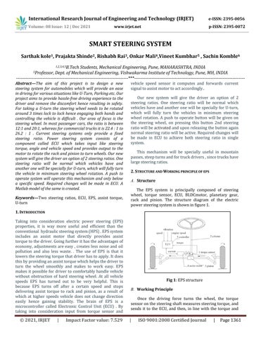
Once the driving force turns the wheel, the torque sensoronthesteeringshaftmeasuressteeringtorque,and sends it to the ECU, and then, in line with the torque and
A. Structure
Keywords Two steering ratios, ECU, EPS, assist torque, U turn 1. INTRODUCTION
Taking into consideration electric power steering (EPS) properties, it is way more useful and efficient than the conventional hydraulicsteeringsystem(HPS).EPSsystem includes an assist motor that directly provides assist torquetothedriver.Goingfurtherithastheadvantagesof economy, adjustments are easy , creates less noise and oil pollution and also less waste. . The use of EPS is that it lowersthesteeringtorquethatdriverhastoapply.Itdoes thisbyprovidinganassisttorquewhichhelpsthedriverto turn the wheel smoothly and makes to work easy. EPS makes it possible for driver to comfortably handle vehicle without obstruction of hard steering wheel. At all vehicle speeds EPS has turned out to be very helpful. This is because EPS turns off after a certain speed and stops delivering assist torque to rack and pinion, as a result of which at higher speeds vehicle does not change direction easily hence gaining stability. The brain of EPS is a microcontroller called Electronic Control Unit (ECU) . By taking into consideration input from torque sensor and vehicle speed sensor it computes and forwards current signaltoassistmotortoactaccordingly..
For taking a U turn the steering wheel needs to be rotated around 3 times lock to lock hence engaging both hands and controlling the vehicle is difficult . Our area of focus is the steering wheel. In most passenger cars, the ratio is between 12:1 and 20:1, whereas for commercial trucks it is 22.4 : 1 to 26.2 : 1 Current steering systems only provide a fixed steering ratio. Power steering system consists of a component called ECU which takes input like steering torque, angle and vehicle speed and provides output to the motor to rotate the rack and pinion to turn wheels. Our new system will give the driver an option of 2 steering ratios. One steering ratio will be normal which vehicles have and another one will be specially for U turn, which will fully turn the vehicle in minimum steering wheel rotation. A push to operate system will operate this mechanism and only below a specific speed. Required changes will be made in ECU. A Matlab model of the same is created.
International Research Journal of Engineering and Technology (IRJET) e-ISSN: 2395-0056 Volume: 08 Issue: 12 | Dec 2021 www.irjet.net p-ISSN: 2395-0072 © 2021, IRJET | Impact Factor value: 7.529 | ISO 9001:2008 Certified Journal | Page1361 SMART STEERING SYSTEM Sarthak kole1, Prajakta Shinde2, Rishabh Rai3 , Onkar Mali4,Vineet Kumbhar5 , Sachin Komble6 1,2,3,4,5B.Tech Students, Mechanical Engineering, Pune, MAHARASHTRA, INDIA 5Professor, Dept. of Mechanical Engineering, Vishwakarma Institute of Technology, Pune, MH, INDIA *** Abstract—
Our new system will give the driver an option of 2 steering ratios. One steering ratio will be normal which vehicleshaveandanotherone will bespeciallyforU turn, which will fully turn the vehicles in minimum steering wheel rotation. A push to operate button will be given on the steering wheel, on pressing this button 2nd steering ratiowillbeactivatedanduponreleasingthebuttonagain normal steeringratiowill beactive.Requiredchanges will be made in ECU to achieve both steering ratio in single system.This mechanism will be specially useful in mountain passes,steepturnsandfortruckdrivers,sincetruckshave largesteeringratios.
2. STRUCTURE AND WORKING PRINCIPLE OF EPS
B. Working Principle
.
The aim of this project is to design a new steering system for automobiles which will provide an ease in driving for various situations like U Turn, Parking etc. Our project aims to provide hassle free driving experience to the driver and remove the discomfort hence resulting in safety.
The EPS system is principally composed of steering wheel, torque sensor, ECU, BLDCmotor, planetary gear, rack and pinion. The structure diagram of the electric powersteeringsystemisshowninfigure1.
Fig 1:EPSstructure

● The basic control for the motor, e.g., by means of space vector management (this generates the mandatory pulse breadth modulation (PWM) for all six electronic transistor switches of the ability module)
● The module needs many inputs, e.g., signals from theanglesensorsthatconfirmthepreciseangular relationoftheelectricalmotor'srotor
Angle 20
● It drives the Power module through its output signals.
● Thecontrolmodule.
Thismoduledeliversthepowertothethree phase motor(mostlybrushlessDC).Thepowerswitches are driven usually by curved pulse breadth modulation that ends up in a curved signal at the phaseoutputsofthepowermodule.
● The predominant system code with communication protocols, fail safe operation and diagnosticfunctions.
●
3. THE CONTROL MODULE
Thesteeringratioisdefinedastheanglebywhichaperson rotatesthesteeringtotheangleby whicha vehicle'sfront tire rotates. Large and heavy duty vehicles have a high steeringratio,ittakesmoresteeringwheelturnsfortrucks and buses to turn the vehicle. In passenger cars steering steering ratio is low as compared, but still it takes significant turns of steering wheel to take u turn . Sport cars have a very low steering ratio, which is necessary for quickandimmediatereactions. HARDWARE PART A. CALCULATIONS
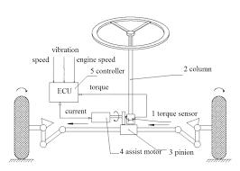
C. Electronic Control Unit
5.
International Research Journal of Engineering and Technology (IRJET) e-ISSN: 2395-0056 Volume: 08 Issue: 12 | Dec 2021 www.irjet.net p-ISSN: 2395-0072 © 2021, IRJET | Impact Factor value: 7.529 | ISO 9001:2008 Certified Journal | Page1362
● Thecontrolsoftware.
B. Steering Ratio
1:
An ECU unit is the Brain of the system and is needed to drive the electric motor. It consists of three principal functionalblocks:
● The temperature is monitored for the Power module, protects against overvoltages and currentsan dcarriesoutemergencymethods justincaseoffailure.
● Thepowermodule.
4. THE POWER MODULE
Fig 2: Electroniccontrolunit
A. Control Software
TABLE Rack Module 2 Pressure
● Additional computing power is needed for sensorless operation since the code must convert the responseof superimposed pulsesintoangular dataoftherotor.
● Theturn on/turn offsequencesareobsessedwith thespeedandforceneedsofthemechanism.
● This module consists of a silicon chip that's mounted on a PCB together with peripheral elements.
vehicle speed, the ECU calculates and obtains an optimum current needed for the assist motor. At the same time, the ECU collects the signals real timely, such as input torque, speed, voltage, current, rotor position of assisting motor, and adjusts the motor current, so as to control the output torque and rotation direction of the assist motor to assist the driver steering in order to gain a better driving experience.Withinthewholemethodofsystemoperating, the fault diagnosing module monitors all elements of the system in real time. Once a failure is detected, the system disconnectstheclutch,andusespuremanualsteering,and offersafaultsignalthatmakessurethedrivingsafety.
Acode tomanage the electrical motor will bedividedinto 2blocks:
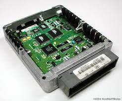
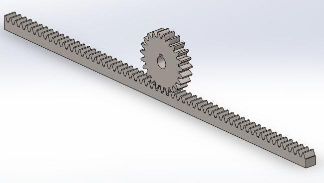
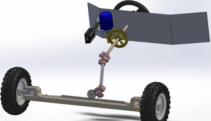
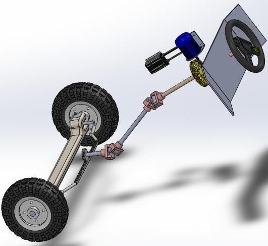
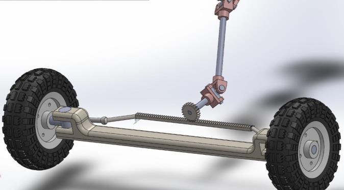
International Research Journal of Engineering and Technology (IRJET) e-ISSN: 2395-0056 Volume: 08 Issue: 12 | Dec 2021 www.irjet.net p-ISSN: 2395-0072 © 2021, IRJET | Impact Factor value: 7.529 | ISO 9001:2008 Certified Journal | Page1363 FaceWidth 10 PitchHeight 10 Length 356 Above measurements are in ‘mm’ TABLE-2: Pinion Module 2 NumberofTeeth 23 PressureAngle 20 FaceWidth 10 PitchCircleDiameter 46 Above measurements are in ‘mm’ TABLE 3: Specifications Wheelbase 1561 Steeringratio 3:1 Racktravel 107.95 Tierodlength 320 Locktolockturns 2.87 Steeringwheeldiameter 200 Above measurements are in ‘mm’ B. PHOTOS Fig 3:RackandPinionassembly Fig 4:Finalassembly Fig 5:Finalassembly Fig 6:Finalassembly
ADC converts the three analog information that three sensors provide. Thedata thatADCprovidesisprocessed using ATMEGA 32 which is a microcontroller . Following logicisusedtodriveEPS ● EPSisenablediftheRPMsensorgiveshighoutput anddisabledifitgiveslowoutput Assoonasvehiclecrosses80Km/hrmarks,speed sensor reacts and gives signal to EPS to turn off and henceforward vehicle runs on pure mechanicalassistedsteering. For eg if the torque sensor gives voltage output as2.5vinthiscasePWM(Pulsewidthmodulation) is0. Incaseofturningwheelstorightorleftdirection, when output of torque sensor is less than 2.5v vehicleturnsleftandviceaversai.e vehicleturns rightwhenoutputismorethan2.5v
B. Assist Map ForthestandardizationofECUgloballyandforsafedriving an assist map is created. In this graph steering torque vs assist torque is plotted. This graph shows amount of torquethatshouldbeprovidedbythemotoratrespective vehicle speeds. The vehicle speed and assist torque are inverselyproportionaltoeachother.Thisisdonetoensure a safe driving experience, hence driver will be able to handle vehicle comfortably even at high speeds. With increase in speed assist motor provides less torque, therefore turning vehicle left or right becomes hard and stabilityisgained.Asvehicletouchesandexceedsthemark of80Km\hrEPSstopsworking,asaresultofwhichdriver needstodelivermoretorquehenceturningvehicleless.As per the assist map, as soon as the driver torque reaches 2Nm, assist motor starts delivering assist torque to rack and pinion and at the same time assist torque will compensate the steering torque so that person will apply 2Nm torque only to turn the wheel . Above mentioned situationisforspeedtill 10Km/hr.Forfurtherconditions and vehicle speeds, ECU will act according to assist map shown.
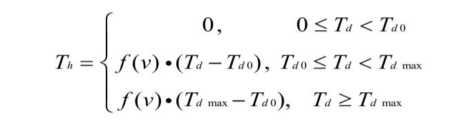
Fig 9:AssistMap C. ECU Logic Assist characteristic of electric power steering refers to therelationshipbetweeninputparametersthataretorque and speed, and output parameter that is assist torque or can be said as current of the motor. When vehicle is in motion as vehicle's speed goes on increasing resistance observed in steering wheel decreases, so the assist torque of motor should decrease with the increase of speed, and when the speed exceeds a certain limit, power of motor is cut off. The three common assist characteristic curves are linear, foldinglinesand curvestype. Outofwhichthe first one that is Linear assist characteristic curves are easy to
International Research Journal of Engineering and Technology (IRJET) e-ISSN: 2395-0056 Volume: 08 Issue: 12 | Dec 2021 www.irjet.net p-ISSN: 2395-0072 © 2021, IRJET | Impact Factor value: 7.529 | ISO 9001:2008 Certified Journal | Page1364 Fig 7: Pushtooperatebutton 6. SOFTWARE PART A. ECU Design Fig 8: ECUBlockDiagram
●
●
●
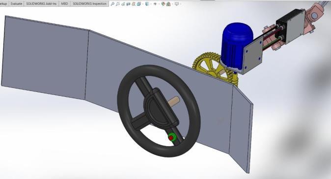
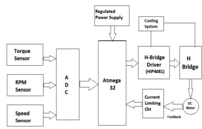
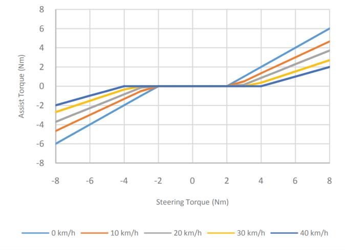
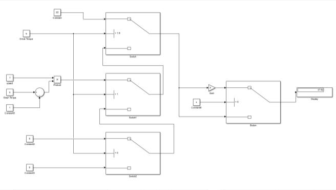
Fig 10: ECUsimulinkmodel
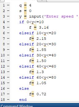
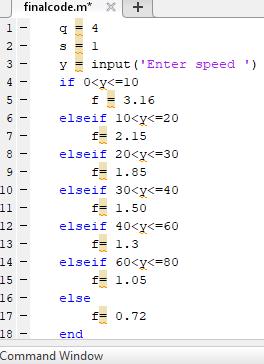
International Research Journal of Engineering and Technology (IRJET) e-ISSN: 2395-0056 Volume: 08 Issue: 12 | Dec 2021 www.irjet.net p-ISSN: 2395-0072 © 2021, IRJET | Impact Factor value: 7.529 | ISO 9001:2008 Certified Journal | Page1365 adjust, simple in form, implement in practice, and used most widely. Linear assist characteristic can be representedasthefollowingfunction Here Th is the assist torque to be provided by the motor , f(v) is coefficient of speed induction . Th max is the maximum capacity the assist motor can provide.,Td0 is theminimuminputtorqueofdriveratthebeginningofthe motor’s output power,Tdmax is the input torque of driver at the maximum power of motor. Establishing the characteristic parameters of assist curves as follows Td0=1Nm, Tdmax=7.6Nm, Th max=22Nm. According to the rules speed induction coefficient is considered. No power is given to motor when the speed is more than 80 km/hr. TABLE-4: Inductioncoefficientofdifferentspeed (Km/hr)Speed 0 10 20 30 40 60 80 CoefficientInduction 63.1 52.1 51.8 01.5 01.3 1.05 w0.72 D. Methodology
To prove that when push to operate button is pressed vehiclewilltakeu turninjust⅕thsteeringtorqueand⅕ th steering angle, we have recorded to outputs keeping sametorqueandvehiclespeedinbothcases
Driver will activate 3:1 steering ratio with a push to operatebuttongivenonthesteeringwheel.Powermodule delivers the power and Control Software operates the assist motor by means of space vector control. This generates the necessary pulse width modulation (PWM) forallsixField effecttransistorFETswitchesofthepower module. Push to operate switch will command ‘Control Software’ and ‘command power module’ to supply assist torque 5 times more in order to achieve 3:1 ratio . Hence withthesamedrivertorquewheelswillturn5timesmore as compared to normal turning when button is active, resultinginthevehiclemakingU turn.
7. RESULTS
TABLE 5: Normal Steering Ratio Extra Steering ratioforUturn value 15:1 3:1 Steering wheel Turns required forUturn 2.5 0.5 Angle covered by steering wheel 900deg 180deg Usually passenger cars have steering ratio 15:1 that meansfortakinguturnsteeringwheelsneedstobeturned 2.5 times i.e 900 deg to either side from idle position. Second steering ratio we are providing to driver is 3:1 which means steering wheel rotates 0.5 turns i.e 180 deg toeithersidefromidleposition
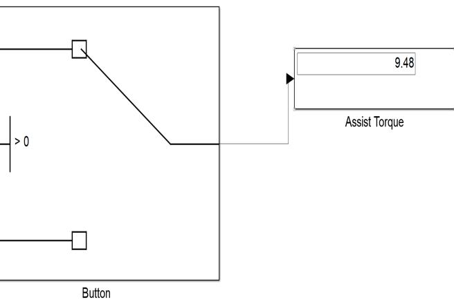
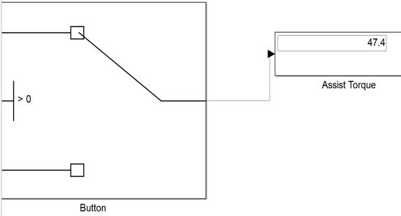
In first outputVehiclespeedis taken as35 Km/hr and Torquegivenbydriveristakenas4Nm.Insecondoutput vehicle speed is kept same i.e 35 Km/hr and torque given by driver is also kept the same i.e 4 Nm ,but in this case push to operate button is pressed hence the second steeringratio(3:1)usedforU turnisactivatedandresults are Displayrecorded.shows assist torque which will be provided by motor
International Research Journal of Engineering and Technology (IRJET) e-ISSN: 2395-0056 Volume: 08 Issue: 12 | Dec 2021 www.irjet.net p-ISSN: 2395-0072 © 2021, IRJET | Impact Factor value: 7.529 | ISO 9001:2008 Certified Journal | Page1366 a) 15:1steeringratio Fig 11:Displayshowingassisttorque(Nm) Fig 12:PushtooperatebuttonOff(s) b) 3:1steeringratio Fig 13:Displayshowingassisttorque(Nm) Fig 14: PushtooperatebuttonON(s) FromFig.11,Fig12,Fig13,Fig14itcanbeconcludedthat onactivatingpushtooperatebuttonassistmotorprovides 5timesmoretorque. 8. ACKNOWLEDGMENT We wouldliketoexpressourspecial appreciation and thanks to our guide, Professor Sachin Komble (Mechanical Department), for his constant support, constructive criticism, and guidance through each stage of theprocess.WearegratefultoProf. Dr.M.B.Chaudharisir HOD, Department of Mechanical Engineering for his valuable guidance and support. Most importantly, we would like to extend our sincere thanks to Prof. Dr. R M Jalnekar sir for his immense knowledge and plentiful experience have encouraged us in all the time of our academicproject.. 9. REFERENCES [1] Electronic Power Assisted Steering System, International Journal of Engineering and Innovative Technology(IJEIT)Volume1,Issue3,March2012 [2] ThePrototypeDevelopmentofElectronicControl Unit for Electric Power Steering, Joint International Conference on Electric Vehicular Technology and Industrial, Mechanical, Electrical and Chemical Engineering(ICEVT&IMECE)2015 [3] Design and Simulation of 4 Wheel Steering System, International Journal of Engineering and InnovativeTechnology(IJEIT)Volume3,Issue12,June 2014
International Research Journal of Engineering and Technology (IRJET) e-ISSN: 2395-0056 Volume: 08 Issue: 12 | Dec 2021 www.irjet.net p-ISSN: 2395-0072 © 2021, IRJET | Impact Factor value: 7.529 | ISO 9001:2008 Certified Journal | Page1367 [4] DESIGN OF STEERING SYSTEM OF FORMULA STUDENT RACE CAR, International Journal of Aerospace and Mechanical Engineering Volume 4 No.2,April2017 [5] Design of Steering GearSysteminPassengerCar: A Review, International Research Journal of EngineeringandTechnology(IRJET)Volume:05Issue: 01|Jan 2018 [6] Analysis and Improvement of the Steering Characteristics of an ATV Dr. S. Neelakrishnan. et al. Int. Journal of Engineering Research and Application www.ijera.comISSN:2248 9622,Vol.7,Issue5 [7] MicroControllerAssistedVariableSteeringRatio andSolutionofPullingofCar. InternationalJournalfor ResearchinAppliedScience&EngineeringTechnology [8](IJRASET)Design of a variable steering ratio for steer by wire vehicle with a joystick Advances in Mechanical Engineering2017,Vol.9(11)1 14 [9] DEVELOPMENT OF FOUR WHEEL STEERING SYSTEM FOR A CAR SASTECH Journal : Volume 12, Issue1,April2013 [10] Modelling and simulation of electric power steeringsystemusingpermanentmagnetsynchronous motors. IOP Conf. Series: Materials Science and Engineering561(2019) [11] Electronic Power Assisted Steering System. International Journal of Engineering and Innovative Technology(IJEIT)Volume1,Issue3,March2012 [12] Electric Power Steering Design Guide With DRV3205 Q1 Texas Instruments Incorporated: SLVA830 October2016 [13] DESIGN OF STEERING SYSTEM OF FORMULA STUDENT RACE CAR International Journal of Aerospace and Mechanical Engineering Volume 4 No.2,April2017 [14] Design of Rack andPinion Steering System for anAllTerrainVehicle©2018IJCRT|Volume6,Issue2 April2018|ISSN:2320 2882 [15] SimulationAnalysisforElectricPowerSteering Control System Based On Permanent Magnetism Synchronization Motor. 2nd International Conference on Electronic & Mechanical Engineering and InformationTechnology(EMEIT 2012)