1. INTRODUCTION
Asdiscussedwiththeirengineersandtechnician,majorproblemsfoundinsidethefictionweldingare:
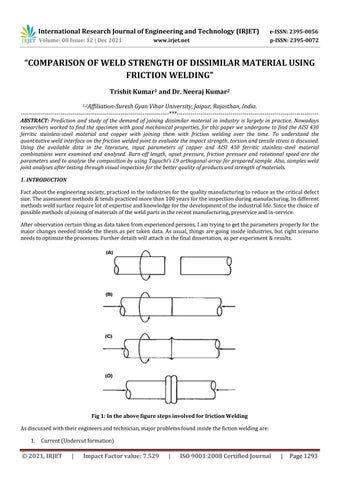
Fig 1: In the above figure steps involved for friction Welding
Factabouttheengineeringsociety,practicedintheindustriesforthequalitymanufacturingtoreduceasthecriticaldefect size.Theassessmentmethods&tendspracticedmorethan100yearsfortheinspectionduringmanufacturing.Indifferent methodsweldsurfacerequirelotofexpertiseandknowledgeforthedevelopmentoftheindustriallife.Sincethechoiceof possiblemethodsofjoiningofmaterialsoftheweldpartsintherecentmanufacturing,preserviceandin service.
Afterobservationcertainthingasdatatakenfromexperiencedpersons,Iamtryingtogettheparametersproperlyforthe major changes needed inside the thesis as per taken data. As usual, things are going inside industries, but right scenario needstooptimizetheprocesses.Furtherdetailswillattachinthefinaldissertation,asperexperiment&results.
1. Current(Undercutformation)
International Research Journal of Engineering and Technology (IRJET) e-ISSN: 2395-0056 Volume: 08 Issue: 12 | Dec 2021 www.irjet.net p-ISSN: 2395-0072 © 2021, IRJET | Impact Factor value: 7.529 | ISO 9001:2008 Certified Journal | Page1293 “COMPARISON OF WELD STRENGTH OF DISSIMILAR MATERIAL USING FRICTION WELDING” Trishit Kumar1 and Dr. Neeraj Kumar2 1,2Affiliation Suresh Gyan Vihar University, Jaipur, Rajasthan, India *** ABSTRACT: Prediction and study of the demand of joining dissimilar material in industry is largely in practice. Nowadays researchers worked to find the specimen with good mechanical properties, for this paper we undergone to find the AISI 430 ferritic stainless steel material and copper with joining them with friction welding over the time. To understand the quantitative weld interface on the friction welded joint to evaluate the impact strength, torsion and tensile stress is discussed. Using the available data in the literature, input parameters of copper and AISI 430 ferritic stainless steel material combinations were examined and analysed. Burn off length, upset pressure, friction pressure and rotational speed are the parameters used to analyse the composition by using Taguchi’s L9 orthogonal array for prepared sample. Also, samples weld joint analyses after testing through visual inspection for the better quality of products and strength of materials.

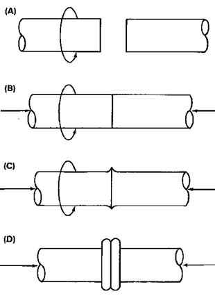
International Research Journal of Engineering and Technology (IRJET) e-ISSN: 2395-0056 Volume: 08 Issue: 12 | Dec 2021 www.irjet.net p-ISSN: 2395-0072 © 2021, IRJET | Impact Factor value: 7.529 | ISO 9001:2008 Certified Journal | Page1294 2. Non quantity(Current&voltage) 3. ThicknessofMaterials(SS,MS,Al) 4. Torchangle 5. Fillerwire 6. Gassetting In this study of friction welding, to improve & innovate the quality of manufactured products in the industry Taguchi methods are used as statistical methods. For the study of the dissimilar metals, here the optimal levels for various specimen, it is hard or impossible to control under uncontrollable conditions for the complete welding process that is, insensitivetonoisefactorsinthecontinuousprocess Enables joining dissimilar metals: It is essential that proper preparations and precautions should be taken for joining dissimilarmetals.Recently,weusedthebimetallicfrictionjointstojoindissimilarmetals.frictionweldingisthatitcanbe usedforthebelowmetalsintherecentresearchandtheiractivity: a) TitaniumtoCopper b) CoppertoAluminium c) Aluminiumtosteel d) Nickelalloytosteel Fig 2: Friction welding above at various stages Toanalyzethedetaildataoffrictionunderthevariousstagesofproductcreation,Minitabsoftwareusedasproblemsolver ofstatisticsdata,withthereferenceoftheseveralinformation. 2. OBJECTIVES OF RESERARCH WORK I. Investigationofdissimilarmaterialtoaccessthedevelopmentofsolid stateconditionsofMildsteelandStainless steelusingthefrictionbetweenthetwosurfacesfordetailconclusion.
2. Several dissimilar metal welding processes is carried out using the material having same diameter, we can also exploretheweldingaswellasmicrostructureevolutionusingdifferentdiameter.
I. Parameterdesign II. Systemdesign III. Tolerancedesign
1. Inthevariousresearchpaper,Ireportedthattheweld strengthofseveraldissimilarmaterialhasbeentastedon singlescalei.e.,UTMtesting,Rockwellhardnesstesting,fatiguetest.
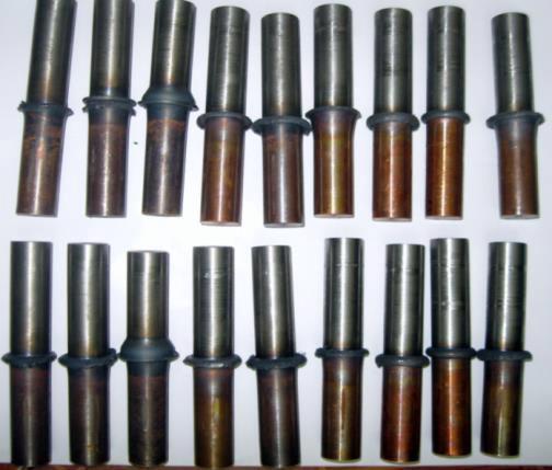
Dissimilar materials of copper and ferritic stainless steel friction welding are shown in Figure 1. In this work cylindrical rodsof25mmdiametersurfacearewellpolishedandcleansthroughthemachining,samplesdiameterofcylindricalrods is24mmand75mminlength.Werepurchased. Samplesofthe frictionweldedspecimenishavingthechangesfoundin theirchemicalcompositionasdetailedinTable1and2.Testingmachinesusedtofindouttheloadtest.Here,weusedthe tensiletestingmachine,withmaximumloadcapacityof75MPato135MPa.Dimensionof60mmx20mmfortensiletest was cut to test all the load conditions. Nozzle size and gas flow rate depends upon the specimen thickness (mm). Therefore,itisasperthethicknessgasflowrateshouldbemaintained.
3. Experimental Methods & Methodology Specimen selection for friction welding
Agapissomethingthatremainstobedoneorlearnedinanareaofresearch;it’sagapintheknowledgeofthescientistin thefieldofresearchofyourstudy:
Figure 3: Specimen visual inspection of welded portion
III. Presentstudyisfordissimilarmetal(mildsteel stainlesssteel)investigatedinthepresentworkthroughthejaws over the machine by rotating at one end and other end is fixed for the applied torque to analyze the torsion & impact test through pendulum fall over the notch opposite ends. The tensile strength of the joints determined, usingaconventionaltensiletestmachine.
Experimental arrangement and their collection form the local and city markets with their complete information about materialselectiondesignfactors.Conceptualizationoftheresearchandsynthesisofnewproductanalysisthatwillsatisfy functionalandeconomicalspecificationstothemarket,thatisobservedforthelifeofproductis:
3. There was lot of parameters (Weld time, burn off length, RPM) which can be varied individually to see their individualeffectsratherthancombiningtheseparameters.
International Research Journal of Engineering and Technology (IRJET) e-ISSN: 2395-0056 Volume: 08 Issue: 12 | Dec 2021 www.irjet.net p-ISSN: 2395-0072 © 2021, IRJET | Impact Factor value: 7.529 | ISO 9001:2008 Certified Journal | Page1295
II. Joiningofdissimilarmetalsnamelystainlesssteelandmildsteelbarsofsamediametertodeterminetheiroptimal conditions.Undertheseconditionsdifferentparametersnamelyaxialpressure,forgepressure,processspeedand theircomprehensiverotationforcewerestudied.
4. I also investigated that some sort of deflection occurred in several instrumental readings, the weld criteria and weldgeometryasforthesameRPMandforsameweldingdimensionthetestresultsvary.
Specimenrotationalspeedsetsbystudyingtheliteraturereviewto920RPM.Leversarethereinsidethelathemachineto adjust the rotational speed over the specimen, the constant speed over the sample was achieved within a fraction of seconds. Before applying the axial pressure, specimen checked for their axial alignment subsequently. Axial pressures differed from paper to paper for present study under composition of alloy, also matter for the different weld joints between 75MPa to 135Mpa. Weld portion will come down at required cooling point after 5 8 minutes of wait after the weldingjointsformed. Parametersforthespecimensizetoformthesamples: i. Samplesizeof24mmx75mmfortheirtestingshouldbeform. ii. DimensionofCylindricalrods(25mm)ofDía.
International Research Journal of Engineering and Technology (IRJET) e-ISSN: 2395-0056 Volume: 08 Issue: 12 | Dec 2021 www.irjet.net p-ISSN: 2395-0072 © 2021, IRJET | Impact Factor value: 7.529 | ISO 9001:2008 Certified Journal | Page1296
Table
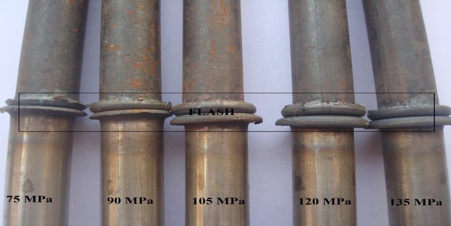
Figure 4: Specimen samples material (copper and ferritic stainless steel for friction welding at different pressure) Dissimilar materials have taken inside this job. Experiments are conducted based on Taguchi’s of 24 mm and 75 mm in length to a diameter. The chemical composition on L9 orthogonal array with three levels of copper and ferritic stainless steel made by friction weldingareshown in table 1,2 &3.The friction welded samplesofthedissimilarmaterial is well polishedandcleanedbyusingacetone. 1: Shows the Ferritic stainless
steel Chemical composition Element% Si Fe S P Mn C Cr Ni 0.551 81.58 0.016 0.023 0.689 0.076 16.52 0.19 Table 2: Shows the Copper Chemical composition Element% Cu Fe 99.99 <0.01 Table 3: Shows the Copper Chemical composition Parameters Level 1 Level 2 Level 3 Rotational speed (rpm) 500 1000 500 Burn off length (mm) 1 2 3 Upset pressure (MPa) 65 87 108 Friction pressure (MPa) 22 33 43
International Research Journal of Engineering and Technology (IRJET) e-ISSN: 2395-0056 Volume: 08 Issue: 12 | Dec 2021 www.irjet.net p-ISSN: 2395-0072 © 2021, IRJET | Impact Factor value: 7.529 | ISO 9001:2008 Certified Journal | Page1297 All the parameters adapted for the friction welding of specimen taken for the readings is shown in below table 4 Nomenclature of rotation per minute is (RPM), materials friction pressure (Pressure P1), materials upset pressure (PressureP2),No.oftimet1(frictiontime),No.oftimet2(upsettime) forgingphaseand heatingphase. Table 4: Different parameters adapted for friction welding Number of trials Friction time (s) (Mpa)pressureFriction speedRotational(RPM) (Mpa)PressureUpset Upset time(s) 1 5 80 1500 150 5 2 5 80 1500 175 6 3 5 80 1500 200 7 4 5 80 1500 300 8 A material constitutes of several substances in their core shown in Table 1. Object is the mixture of materials and their substance.Itcanbetheirphysicalandchemicalpropertiestotheirbiologicalfunctionandgeologicaloriginwhich retainit as their existence in pure or impure. This required their integrity to be retained during imaging. To achieve this prior to FIBpreparationofsamples. Table 5: Different parameters adapted for friction welding SAMPLE NO. DISTANCESTANDOFF(inch) OXYGEN FLOW RATE(m3/min) LPG FLOW RATE(m3/min) POWDER FEED RATE (gm/min) 1 7 180 70 14.09 2 7.7 265 64 14.09 3 8.5 35 58 14.09 4 7.7 180 58 15.94 5 8.5 265 70 15.94 6 7 350 64 15.94 7 8.5 180 64 17.80 8 7 265 58 17.80 9 8.5 350 70 17.80 Microstructuresofthecoatingonsubstratemetalplateare A. Micro hardnessofthecoatedmaterialonstainlesssteelplates. B. Porosityvolume%fractiontesting. C. ScanningElectronMicroscopy D. CoatingThicknessmeasurement. There was lot of parameters (Weld time, burn off length, RPM) which can be varied individually to see their individual effectsratherthancombiningtheseparameters. 4. RESULTS&DISCUSSIONS As evaluated for the combinations of materials in the alloy with the visual examination like impact strength, micro hardness,andtensilestrengththroughthemachinetoidentifytheconclusionfortheproductformed Ithasbeenobserved from the tensile test of the tested materials, by the specimen magnified images were captured samples to know their strengthintensionatthefracturedlocationstakenat1,500Xmagnification
Tensile Testing
4.2
Torsion Test Analysis
Analysisthroughscientificinstrumentsperformedfortorsiontestofthesamples.Torsiontestforthespecimenappliedtill samplegetsfractured.Everysamplefittedtomachine,machinehavetwojawsinwhichonesideitwaskeptfixed,andthe othersideofjawwillrotateatappliedtorque.So,overthemachineitgetstwistedovertheappliedtorque,degreeoftwist of the specimen called angle of twist and measured angle of twist said to be application of torque. During measured applicationoftwistingmomentallspecimenstartstwistingforthechangeformedatangleandthespecimenangleoftwist foreverysampleintermsofdegreesvariedfrom70to160andsampleformaximumtorsionstrengthforthetestsvaried from1182Nmto21.10Nm.Foreverysampleatintervalof5min,wechangethetorquebyincreasingitanditchangethe angleoftwist.Also,increaseinaxialpressurefromtheexperimentnotedthatangleoftwistincreasesforthesample.
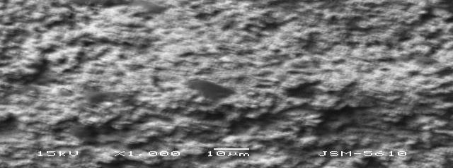
Fig 5: SEM of the coating at X1000 of particle size 10 µm.
4.1
International Research Journal of Engineering and Technology (IRJET) e-ISSN: 2395-0056 Volume: 08 Issue: 12 | Dec 2021 www.irjet.net p-ISSN: 2395-0072 © 2021, IRJET | Impact Factor value: 7.529 | ISO 9001:2008 Certified Journal | Page1298
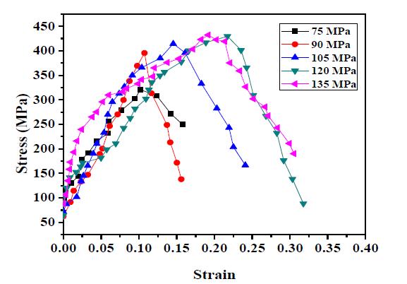
Figure 6: Relationship of Strain vs Stress (Mpa) at pressure exerted at axial point
Foreveryspecimentensiletestweresubjectedandrecordedfordifferentspecimenloadapplieduntilitfracturesandgets distorted from inside. Universal Testing Machine (UTM) used to perform the tensile test over the specimen and here machineusedishavingthecapacityof600KN.SamplespreparedthroughtheASTMstandardandspecimengaugelengths were maintained for everysampleasdetailed inASTM A370 12tokeepthegaugelengthincenterofthe weldinterface. Samples one by one tested and result for tension, axial tensile stress, fracture recorded at the variations of load. Tensile stressVsstraingraphplottedaftertheresult analysis,anditshowstheincreasein stress foreverychangeorincreasein strain
International Research Journal of Engineering and Technology (IRJET) e-ISSN: 2395-0056 Volume: 08 Issue: 12 | Dec 2021 www.irjet.net p-ISSN: 2395-0072 © 2021, IRJET | Impact Factor value: 7.529 | ISO 9001:2008 Certified Journal | Page1299 Fig 7. Specimen SEM image at 75 & 90 MPa axial pressure Figure 8: SEM image at 105 & 120 MPa axial pressure Figure 9: SEM image at 135 MPa axial pressure
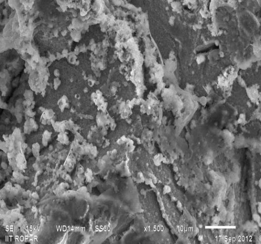
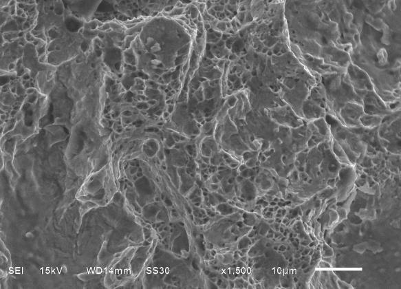
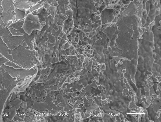
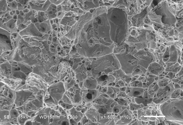
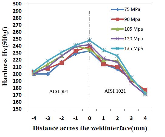
Figure 10: Shown the material Weld interface vs Hardness variations distance Attheweldinterfaceallthematerialsusedtoformthealloycombinationsishaving indentationsofhighervaluesandon bothweldfaces,alsointerfacewasprobablyplaceduringfrictionwelding.Inadditiontohardnessoxidationprocesswhich takes at the increase in hardness variations. Once the details for whole collected data through testing analyzed the followingresultsobtainedfromMinitabsoftwareforthetesting.
International Research Journal of Engineering and Technology (IRJET) e-ISSN: 2395-0056 Volume: 08 Issue: 12 | Dec 2021 www.irjet.net p-ISSN: 2395-0072 © 2021, IRJET | Impact Factor value: 7.529 | ISO 9001:2008 Certified Journal | Page1300 UsingimpacttestingmachinewiththemethodofpendulumtypesingleblowtestwascarriedoutforCharpyimpacttest. ASTM standards set for the sample preparation to form the notch at the center of sample weld interface. at both ends specimensweresupportedanditwascheckbybrokingthe sampleoppositesideofnotchbydroppingthependulum.So, foreverydroptherewillbetestnotedandshownintablefortheirrelativechangeofimpactaroundthesamples. Table 6: Samples with their impact strength relation SampleNo CharpyImpact(J) IzodImpact(J) Axial Pressure (Mpa) FractureLocation S1 25 20 75 weldinterface S2 25 20 90 weldinterface S3 24 19 105 weldinterface S4 23 19 120 weldinterface S5 21 19 135 weldinterface 4.3 Micro hardness testing
In this test apply the load along the axis at the intervals of 1 mm which is constant on the alloy combination of using the Vickers hardness testing machine. A potentiodynamic polarization curves obtained as shown in figure 10 through the test on the parent materials for the applied load of 500 gf. Affect of heat as indentations for the parentmaterialtofindthe hardnessandtheirvariations tested,basedpyramidtypediamondanalysisofmicrohardness testingofmaterialsachievethelengthofthehardnessrequiredforthecombinationofmaterials.
we
materials by
International Research Journal of Engineering and Technology (IRJET) e-ISSN: 2395-0056 Volume: 08 Issue: 12 | Dec 2021 www.irjet.net p-ISSN: 2395-0072 © 2021, IRJET | Impact Factor value: 7.529 | ISO 9001:2008 Certified Journal | Page1301
To reduce temperature length graph and the heat input variations inside the slope curve for the theoretical basis is the same. It increases with the root gap and decreases cracks the slope curve with the root gap spaces affected by the temperaturegradients. Timeisconsideredforthefractionweldinginsidethezone formaximumandminimum asfound which.iseasiertotimecurve.
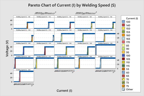
of Current (I) by Welding Speed (S)
ParetoANALYSISChart
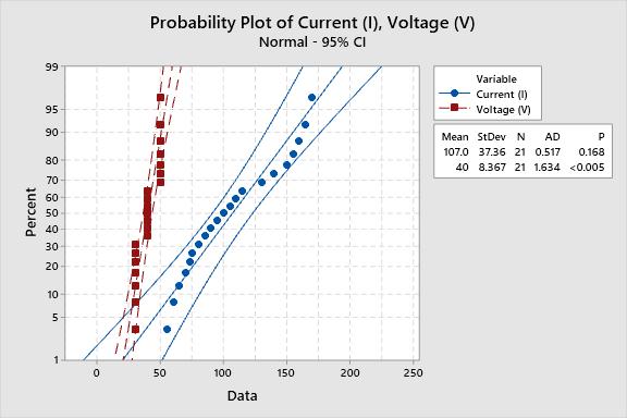
ProbabilityANALYSIS
Fig 12: Minitab graph pareto chart fraction welded specimen and their welded sample
Plot of Current (I), Voltage (V)
4.4 OPTIMISATION
Temperatureoftheheatgeneratedandthesampleresultsatthetimeinterval.Resultsareshowninbelowfigureno.12for the applied eddy current and infrared image of the system was in the high temperature regions. Temperature gradients willincreasegraduallyandthesegradientsfromthethermalimagehaveofcrackshavemorebrightareaof2saroundthe crackacrossthesampletaken,whichhavebrightareasoftheimagewastaken
Fig 11: Minitab graph welding current 100,110, 120, 130 and 170 are used over the welded specimen and their welded sample
[9] HANDA, A., CHAWLA, V.: (2014b), “An investigation on the effect of axial pressures on the mechanical properties of frictionweldeddissimilarsteels”,AdvancesinMechanicalEngineering,Vol.2014,2014,pp.1 6.
[10] HANDA, A., CHAWLA, V.: (2014c), “Investigation of mechanical properties of friction welded AISI 304 with AISI 1021dissimilarsteels”,InternationalJournalofAdvancedManufacturingTechnology,Vol.75,2014,pp.1493 1500.
ii. In friction welded joint this low upset pressure decreases in impact toughness when burn off length is higher. Also,qualityandthestrengthofthebondforbothmaterialsjoinedalsovariedwitheachother.
[5] HANDA, A., CHAWLA, V.: (2013a), “Mechanical characterization of friction welded dissimilar steels at 1000 rpm”, Mater.Eng. Mater.Inz,Vol.20,2013,pp.102 111.
[6] HANDA, A., CHAWLA, V.: (2013b), “Experimental study of mechanical properties of friction welded AISI 1021 steels”, Sadhana AcademyProceedingsinEngineeringSciences.,Vol.38,2013,pp.1407 1419.
This model can be applicable for all properties of defined materials for the thickness of the ferritic stainless steel. The porous coating was found to be low compared to other thermal spraying coatings. which is a necessary condition for obtaining sound joint. All the materials with dissimilar nature evaluated for their material properties as tested and analysishavesomeconclusionbasedontheirresultsasobtained.
i. The impact toughness values for ferritic stainless steel and copper obtained in which Friction welding for both materialsjoinedsuccessfully.Also,materialjointshavebeendifferentascomparedwiththeirpoints.
iv. In this test due to temperature rise, impact toughness of the welded joint will result in poor accumulation of alloying elements. Also, presence of intermetallic layers has joined their elements at their weld interface with sustainablesurfacelayer.
iii. Frictionweldedjointforincreaseintoughnessofweldedjointwiththeresultof14J/cm2withlowburn offand highupsetpressureshowswith46J/cm2.
v. ImpacttestedsamplewithFractureanalysisresultinductilemodeoffractureinthedifferentmagnificationswas madewithdimpleformation.
[4] CHAWLA, V., BATRA, U., PURI, D., CHAWLA, A.: (2008), “To study the effect of au tempering temperature on fracture behaviour of Ni Mo au tempered ductile iron”, Journal of Minerals & Materials Characterization & Engineering, Vol. 7, 2008,pp.307 316.
[7] HANDA, A., CHAWLA, V.: (2014), “Influence of process parameters on torsional strength, impact toughness and hardnessofdissimilarAISI304andAISI1021frictionweldedsteels”,Mater.Eng. Mater.Inz,Vol.21,2014,pp.94 103.
[2]ARIVAZHAGAN,N.,SINGH,S.,PRAKASH,S.,REDDY,G.M.:(2008)“Anassessmentofhardness,impactstrengthandhot corrosion behavior of friction welded dissimilar weldments between AISI 4140 and AISI 304”, International Journal of AdvancedManufacturingTechnology,Vol.39,2008,pp.679 689.
[1]ANANTHAPADMANADAN,D.,RAO,V.S.,ABRAHAM,N,RAO,K.P.:(2009),“Astudyofmechanicalpropertiesoffriction weldedmildsteeltostainlesssteeljoints”,MaterialsandDesign,Vol,30,2009,pp.2642 2646.
REFERENCES
[8] HANDA, A., CHAWLA, V.: (2014a), “Experimental evaluation of mechanical properties of friction welded dissimilar steels”,CogentEngineering,Vol.1,2014,pp.1 10.
5. CONCLUSIONS
International Research Journal of Engineering and Technology (IRJET) e-ISSN: 2395-0056 Volume: 08 Issue: 12 | Dec 2021 www.irjet.net p-ISSN: 2395-0072 © 2021, IRJET | Impact Factor value: 7.529 | ISO 9001:2008 Certified Journal | Page1302
[3]ARIVAZHAGAN,N.,SINGH,S.,PRAKASH,S.,REDDY,G.M.:(2011),“InvestigationofAISI304austeniticstainlesssteelto AISI4140lowalloysteeldissimilarjointsbygastungstenarc,electronbeamandfrictionwelding”,MaterialsandDesign, Vol.32,2011,pp.3036 3050.
International Research Journal of Engineering and Technology (IRJET) e-ISSN: 2395-0056 Volume: 08 Issue: 12 | Dec 2021 www.irjet.net p-ISSN: 2395-0072 © 2021, IRJET | Impact Factor value: 7.529 | ISO 9001:2008 Certified Journal | Page1303 BIOGRAPHY NAME TRISHITKUMAR DESIGNATION M.TECHSCHOLOR AFFILIATION SURESHGYANVIHARUNIVERSITY,JAIPUR,RAJ. NAME DR.NEERAJKUMAR DESIGNATION HEADOFMECHANICALDEPARTMENT AFFILIATION SURESHGYANVIHARUNIVERSITY,JAIPUR,RAJ.