1. INTRODUCTION
Iftheengineisconsideredtobetheheartofthevehicle,thentheheartofthedieselengineisthefuelinjectionequipment (FIE).TheFIEpumpsthedieselfueltotheenginethatisrequiredforittooperate.Italsoaffectstheengine'soutputandmostof theenginecharacteristicsaredependentontheFIE'sperformance.TheFIE'svalueissuchthatmuchofthedieselengine's productionhasbeencloselyrelatedtotheFIE'sdevelopmentovertheyears.
1.1 Diesel Engine
1.2Direct and Indirect Fuel Injection
In 2016, FuyingXue , FuqiangLuo, Huifeng Cui, Adams Moro, Liying Zhou[1] Thisarticlementionsthedefinitionandmodel ofmathematicsrelatingtocavitationandturbulence.Theturbulenceflowpatternandcavitationevolutionfornozzleholesofan asymmetricmulti holedieselinjectorwerereproducedusingthemulti phasetwofluidflowapproaches,wheretheeffectof injectionconditionsonthebubblenumberdensitywasconsidered.Thefuelflowcharacteristicsofeachnozzlecavityhavebeen simulated, the fuel flow characteristics have been simulated and cavitation and turbulence effects have been analyzed. In cavitation,theevolutionofholeshasvariedgreatly.Nozzleanglesandneedleliftingmechanismshavebeenfoundto affect cavitation,massmovementandspeedofflow.
International Research Journal of Engineering and Technology (IRJET) e ISSN: 2395 0056 Volume: 08 Issue: 12 | Dec 2021 www.irjet.net p ISSN: 2395 0072 © 2021, IRJET | Impact Factor value: 7.529 | ISO 9001:2008 Certified Journal | Page1231 CFD Analysis of Fuel Injection System using ANSYS CFX Ankit Kumar Tiwari1, Purushottam Kumar Sahu2 1Research Scholar BM College of Technology, Indore RGPV Bhopal 2Professor BM College of Technology, Indore RGPV Bhopal *** Abstract -
In the current study, fuel injection engine CFD analysis is performed to determine the design parameters produced by thrust force and static enthalpy. The design parameters are related to the number of fuel inlets, i.e. (1, 3 and 5). The quantity of fuel intake has a significant effect on combustion, which in turn affects the enthalpy output and thus the thrust strength. The Eddy dissipation combustion model used for CFD analysis provides a better approximation of fluid flows compared to other techniques. The pressure plot of all designs shows the highest pressure value in the combustion zone for all design configurations (1, 3 and 5 inlets). The pressure decreases along the length of the fuel injection engine tube and along the length of the fuel injection engine tube highest being in the combustion zone
Key Words: FuelInjector,Nozzlegeometry,dieselfuel,Outletvelocity,TransientFuelSprayFormation,optimization
Bothdieselengineshavefuelinjectionsystems,unliketraditionalpetrolengines,alsoknownasspark ignition(SI)engines withcarburettors.Themethodofinjectionfallsintooneoftwotypes,namelyDirectInjection(DI)orIndirectInjection(IDI).As thenameindicates,directinjectionapplies,seeFigure1.1,toallsystemsinwhichfuelisdirectlyinjectedintothecombustion chamber.Inasmallpre chamberorturbulencechamberinIDIengines,arelativelyrichfuelmixtureisfirstignited,seeFigure 1.2,andthisburningmixturethenpassesintothemaincombustionchamber,whereitmixeswiththeremainingcompressed airandburnsitveryeffectively.Traditionally,onlyIDIsystemshavebeenusedindieselpassengervehicles.Thiswasdueto relativelysmoothcombustion,loweroperatingnoiseandthefuelinjectionsystem'srelativelylowrequirementstoachieve successfulhigh speedfuel/airmixing.However,DIdieselenginesconsume10 15%lessfueland,naturally,thishasledtothe developmentofcarengineswithdirectfuelinjectionintoapiston bowllocatedeccentrictothepistonaxis.
Dr.RudolfDieseldevelopedtheDieselengine,alsoknownasacompression ignitionengine,inanefforttoimprovethespark ignitionengine'scomparativelypoorthermalefficiencybyusingahighercompressionratio.Duringtheengine'scompression stroke,theairinthecombustionchamberisheatedtosuchadegreethatitself igniteswhenthefuelisinjected.Duringthe initialenginedevelopment,injectingthefueldirectlyintotheengineprovedunsatisfactory,andsocompressedairwasusedto force it into the combustion chamber. This air blast injection process, however, was slow and costly and was ultimately replacedbyamechanicaldevice.Thesystemthathasbeengenerallyacceptedwasthe'jerkpump‘systeminwhichaninjection pumpmetersthefuelandinjectsitathighpressurethroughsmall holeinjectorsintothecombustionchamber.
1.1 Literature Review

In 2015, HengzhouWo , Karl D. Dearn , Ruhong Song , Enzhu Hu , YufuXu , Xianguo Hu [6] Duringadieselprocessusingan emulsion method, the blendof biomass oil anddiesel was preparedandcombusted.An injectorwasthen extracted anda combination of HRTEM, SEM/EDAX, Raman and XRD represented the morphology, composition, and structure of the carbonaceous deposits on the pintle type nozzle. The results revealed that the carbon deposition of the high crystalline emulsifiedfuelwasgreaterthanthatofdiesel.About10 30μmand50μmrespectivelyweretheagglomeratedparticulate diametersofthedepositedcarbonfromdieselandemulsifiedgasoline.Theprocessofemulsifiedfuelcarbondepositionwasdue tothehighoxygencontentofthegroups,resultinginincreasedpolymerizationandeventualcondensationofthecarbonized nozzlesurfaces.
3.Theinterfacebetweentheliquidandthemixingsectionisconstantthroughoutthechokingtime. 4.Theoutletvelocityincreasesduringthechokingtimeasthebackpressuredecreases.
In 2016, F.J. Salvador, D. Jaramillo, J. V. Romero, M. D.Rosello[2] Inthispaper,thebehavioroftheinternalnozzleflowand cavitation phenomena was numerically analyzed for non conventional Diesel convergent divergent nozzles in order to determinetheirabilityintermsofflowcharacteristics.Thenozzlesusedvaryfromeachotherinthedegreeofconvergence divergenceoftheorifices,buttheyallmaintainthesamediameteratthecenterofthenozzleorifice.Usingabiphasicfluid homogeneousequilibriummodelandusingaRANStechnique,thecalculationsareperformedusingacodepreviouslyvalidated andreadytosimulateacavitationphenomenon.Oneinjectionpressureandvariousdischargepressureswereusedforthe simulationsinordertotestnozzlecharacteristicsfordifferentReynoldsconditionsinvolvingcavitation.
International Research Journal of Engineering and Technology (IRJET) e ISSN: 2395 0056 Volume: 08 Issue: 12 | Dec 2021 www.irjet.net p ISSN: 2395 0072 © 2021, IRJET | Impact Factor value: 7.529 | ISO 9001:2008 Certified Journal | Page1232
2.Thedischargecoefficientdeclinesasthebackpressuredecreasesduringthechokingperiod.
In 2016, F.J. Salvador, J. De la Morena.Martínez López. Jaramillo [3] Anstudyofcompressibilityeffectsinnozzleflow simulations for injection pressures of up to 250 MPa was carried out in this paper. During a broad variety of boundary conditions,thefluidproperties(includingdensity,viscosityandspeedofsound)aredeterminedtodoso.Asa functionof pressureandtemperature,thesemeasurementshaveallowedcorrelationstobeobtainedforthefluidproperties.Thenthese equationsareimplementedintoaCFDsolverinordertotakeintoaccountthevarianceofthefluidpropertieswithpressure changesalongthecomputationaldomain.Comparedtoexperimentalmassflowandoutcomesofmomentumflux
In 2016, V. Lazarev, G. Lomakin, E. Lazarev [4]Theperfectionofthedieselengineperformanceparametersistakeninto accountasaresultoftheincreaseinrailpressureandthemodernizationofthenozzleTribosystemshaveahigh(upto300 MPa) fuel pressure value. The updated configuration nozzle and extra (bottom) precision guiding interface are used and hydrodynamic injection parameters are evaluated. Computational fluid dynamic (CFD) modeling is used to estimate hydrodynamicfuelflowandforcedistributionparameterswithinthe"needle nozzlebody"framework.Theoutcomesofthe injectionmodelingaredefinedandtheparametersforthechangeddesignofnozzleprecisioninterfacesarecommunicated.The waysofacceleratingthesteadinessofneedlepositionwithinthenozzlebodywithperfectionofparametersoffuelinjection systemarepresented.
In 2013, Zhixia He, WenjunZhong,QianWang,ZhaochenJiang,ZhuangShao[7] Aflowvisualizationexperimentdevicewith atransparentscaled upmulti holeinjectornozzletipwassetupandastrongagreementwasfinallyshownbetweenthetwo datasetsinordertocomparethemeasuredresultsfromthethree dimensionalnumericalcavitatingflowsimulationinthe nozzlewithamulti phasecavitatingflowmodelmixturetoobtaintheexperimentaldata.Innumericalsimulations,aswellasthe relationshipbetweenthedischargecoefficientandthenon dimensionalcavitationparameter,thecriticalconditionsforthe beginningofcavitationwerederived.
In 2016, Tao Qiu , Xin Song, Yan Lei, Hefei Dai , Chunlei Cao , HuiXu , Xiang Feng [5] Thisworkexplorestheeffectsofthe injectionbackpressureonthedevelopmentofinternalcavitationofthenozzle,especiallytheflowcharacteristicduringthe chokingprocess.Thefollowingarethemainobservations:Thecavitationprocessissplitinto3phasesasthebackpressure decreases.
Subsequently,thetestednumericalmodelswereunabletoexaminetheeffectsonthecavitatingflowinsidethenozzleofnozzle saclength,orificeinletcurvature,orificeinclinationangle,injectorneedleelevationandneedleeccentricity.Theresultsof numericalsimulationwillclearlydemonstratethethree dimensionalnatureoftheflowofthenozzleandthelocationandform ofthevapordistributioncausedbycavitation,whichwillhelptobetterunderstandtheflowofthenozzleandultimatelyput forwardtheprinciplesofoptimizationofdieselinjectors.
1.Duringthetimeofchoking,therearpressurehaslittleinfluenceonthemassmovement.
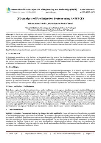
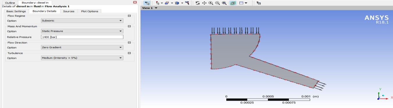
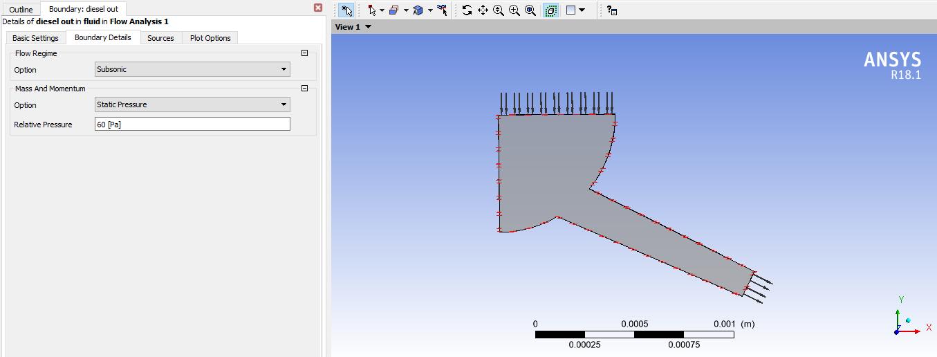
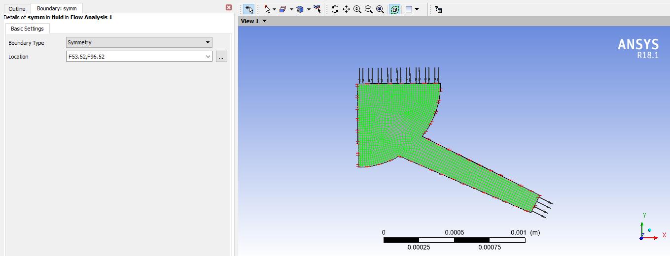
International Research Journal of Engineering and Technology (IRJET) e ISSN: 2395 0056 Volume: 08 Issue: 12 | Dec 2021 www.irjet.net p ISSN: 2395 0072 © 2021, IRJET | Impact Factor value: 7.529 | ISO 9001:2008 Certified Journal | Page1233 In 2014, Sanghoon Lee , Sungwook Park [11] Thispaperanalyzes,asacomparison,thesprayfeaturesofagroup hole nozzleasopposedtothecharacteristicsofasingle holenozzleintermsofsprayoperationandatomizationphase.Phase DopplerParticleAnalyzers(PDPA)andsprayvisualizationexperimentshavebeenperformedusingacustomizableGDIinjector thatcanadoptaparticularnozzleshapeunderfreesprayconditions.g Boundary conditions Thedomainisdefinedasfluid.Referencepressureissetto1atm.Twovariablek epsilonturbulencemodelissetforanalysis andinletpressureissetto1400barandoutletpressureissetto60Pa.Theinletboundaryconditionisdefinedwithdifferent massfractioncompositionofgasesandsameforfuelinletalso. PressureInlet 1400bar 2.PressureOutlet 60bar 3.Temperature 300K 4.TurbulenceKineticEnergy 1m²/s² 5.TurbulenceDissipationRate 1m²/s³ Figure5.5Inletpressureonfuelinjector Figure5.6Outletpressureonfuelinjector The2sidesurfacesareappliedwithsymmetricboundaryconditionsasshowninfigure6.7below.Thesymmetricboundary conditionssimulatetheconditiononbothsides.
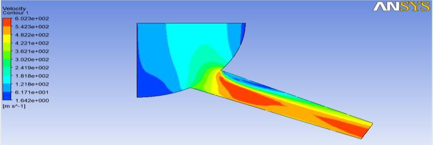
Thecontourplotofvelocityshowshighervalueatnozzleasshownbyredcolouredzonewithmagnitudeof602.3m/sand reducedvelocitynearwallsofnozzleasshownindarkbluecolourwithmagnitudeof1.642m/s.Theoutletportionofnozzlehas alsohighervelocitycomparedtorestof
Figureregion.6.2:VelocityplotfordieselfuelwithD=.140
International Research Journal of Engineering and Technology (IRJET) e ISSN: 2395 0056 Volume: 08 Issue: 12 | Dec 2021 www.irjet.net p ISSN: 2395 0072 © 2021, IRJET | Impact Factor value: 7.529 | ISO 9001:2008 Certified Journal | Page1234 Figure5.7Symmetricboundaryconditiononfuelinjector
6.1 Diesel fuel with D=.140
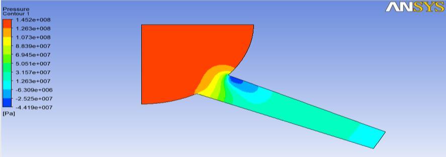
Thecontourplotofpressureshowshighervalueatinletasshownbyredcolouredzonewithmagnitudeof1.452*108Pawhile tensilepressureisgeneratednearoutletasshownindarkbluecolorwithmagnitudeof4.41*107Pa.
The CFD analysis of fuel injector is conducted using ANSYS CFX to obtain pressure plot, velocity plot, eddy viscosity and turbulencekineticenergyfordifferentvaluesofDi.e.140,.150and.169.Thedetailsarediscussedinsectionbelow.
Results and Discussion
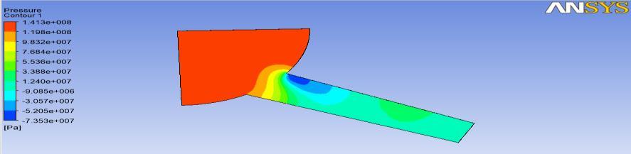
Figure6.1:PressureplotfordieselfuelwithD=.140
International Research Journal of Engineering and Technology (IRJET) e ISSN: 2395 0056 Volume: 08 Issue: 12 | Dec 2021 www.irjet.net p ISSN: 2395 0072 © 2021, IRJET | Impact Factor value: 7.529 | ISO 9001:2008 Certified Journal | Page1235
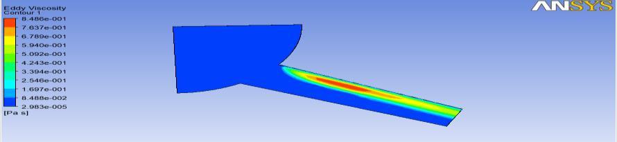
Figure6.3:EddyviscosityplotfordieselfuelwithD=.140
TheeddyviscosityplotforD=.140showshighermagnitudenearwallsofnozzletowardsexitasshowninredcolouredzone withmagnitudeof.575PaSanddecreasesaswemoveawayfromwallasshownbylightblueanddarkbluecolouredregions.
6.2 Diesel fuel with D=.150
Thecontourplotofpressureshowshighervalueatinletasshownbyredcolouredzonewithmagnitudeof1.453*108Pawhile tensilepressureisgeneratednearoutletasshownindarkbluecolorwithmagnitudeof5.142*107Pa.
Figure6.4:PressureplotfordieselfuelwithD=.150 Thecontourplotofvelocityshowshighervalueatnozzleasshownbyredcolouredzonewithmagnitudeof620.4m/sand reducedvelocitynearwallsofnozzleasshownindarkbluecolourwithmagnitudeof1.888m/s.Theoutletportionofnozzle hasalsohighervelocitycomparedtorestofregion.
Figure6.5:VelocityplotfordieselfuelwithD=.150 Figure6.6:EddyviscosityplotfordieselfuelwithD=.150
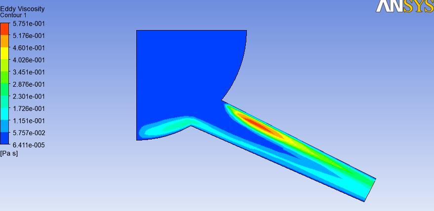
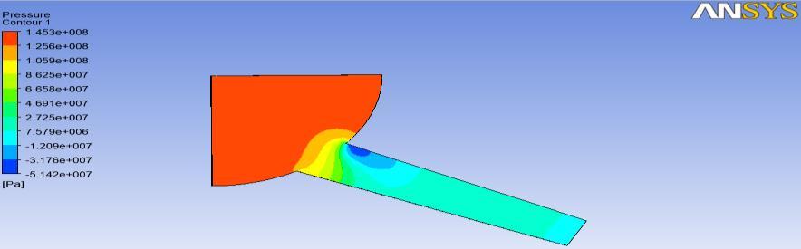
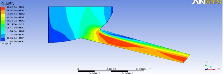
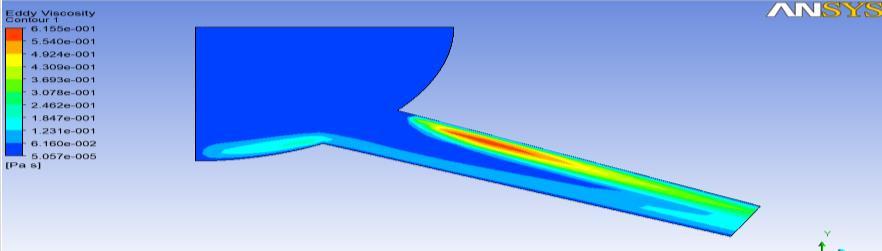
Figure6.7:PressureplotfordieselfuelwithD=.169
Figure6.9:EddyviscosityplotfordieselfuelwithD=.169 Table6.1:OutletVelocitytable D=.169 D=.150 D=.140 DIESEL
6.3
International Research Journal of Engineering and Technology (IRJET) e ISSN: 2395 0056 Volume: 08 Issue: 12 | Dec 2021 www.irjet.net p ISSN: 2395 0072 © 2021, IRJET | Impact Factor value: 7.529 | ISO 9001:2008 Certified Journal | Page1236
TheeddyviscosityplotforD=.169showshighermagnitudenearwallsofnozzletowardsexitasshowninredcolouredzone withmagnitudeof.8486PaSanddecreasesaswemoveawayfromwallasshownbylightblueanddarkbluecolouredregions.
Thecontourplotofpressureshowshighervalueatinletasshownbyredcolouredzonewithmagnitudeof1.413*108Pawhile tensilepressureisgeneratednearoutletasshownindarkbluecolorwithmagnitudeof7.353*107Pa.
526.41 528.07 527.62 DME 591.56 590.625 587.73
TheeddyviscosityplotforD=.150showshighermagnitudenearwallsofnozzletowardsexitasshowninredcolouredzone withmagnitudeof.615PaSanddecreasesaswemoveawayfromwallasshownbylightblueanddarkbluecolouredregions. Diesel fuel with D=.169
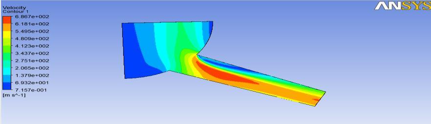
Thecontourplotofvelocityshowshighervalueatnozzleasshownbyredcolouredzonewithmagnitudeof686.7m/sand reducedvelocitynearwallsofnozzleasshownindarkbluecolourwithmagnitudeof.715m/s.Theoutletportionofnozzlehas alsohighervelocitycomparedtorestof Figureregion.6.8:VelocityplotfordieselfuelwithD=.169
FUEL
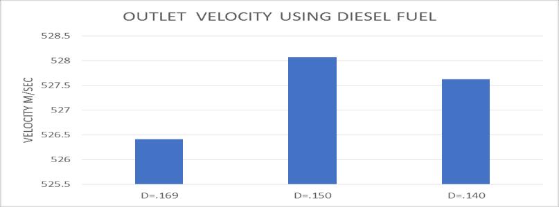
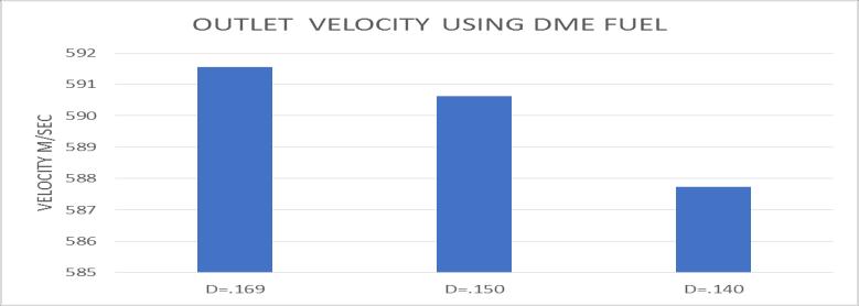
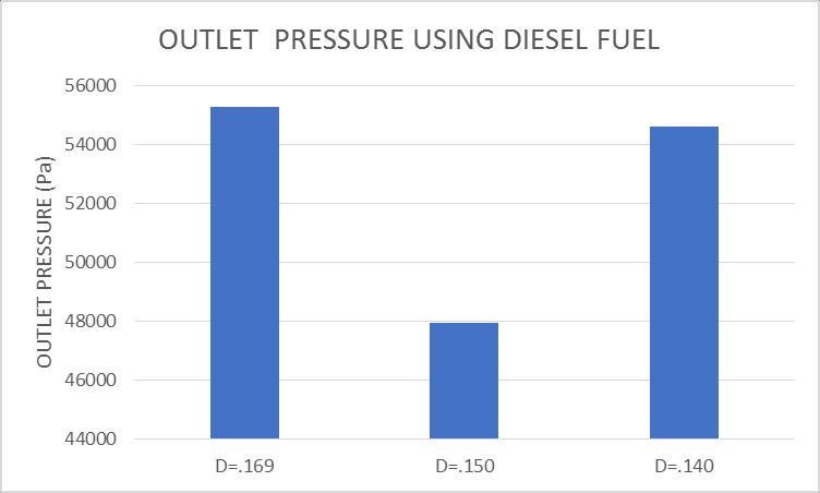
International Research Journal of Engineering and Technology (IRJET) e ISSN: 2395 0056 Volume: 08 Issue: 12 | Dec 2021 www.irjet.net p ISSN: 2395 0072 © 2021, IRJET | Impact Factor value: 7.529 | ISO 9001:2008 Certified Journal | Page1237 Figure6.10:Outletvelocitycomparisonusingdieselfuel Fromoutletvelocitycomparisonchartobtainedfordieselfuelitisevidentthatmaximumvelocityofdieselfuelisobservedfor D=.150followedbyD=.140andminimumforD=.169. Figure6.11:OutletvelocitycomparisonusingDMEfuel FromoutletvelocitycomparisonchartobtainedforDMEfuelitisevidentthatmaximumvelocityofDMEfuelisobservedfor D=.169followedbyD=.150andminimumforD=.140.Table6.2:Outletpressure FUEL D=.169 D=.150 D=.140 DIESEL 55281.1 47946.3 54607.7 DME 44675.2 47262.7 63999.9 Figure6.12:Outletpressurecomparisonusingdieselfuel Fromoutletpressurecomparisonchartobtainedfordieselfuelitisevidentthatmaximumpressureofdieselfuelisobserved forD=.169followedbyD=.140andminimumforD=.150.
[1]FuyingXue,FuqiangLuo,HuifengCui,AdamsMoro,LiyingZhou,“Numericalanalysesoftransientflowcharacteristicswithin eachnozzleholeofanasymmetricdieselinjector”,InternationalJournalofHeatandMassTransfer104(2017)18 27
196
[5]TaoQiu,XinSong,YanLei,HefeiDai ,ChunleiCao ,HuiXu ,XiangFeng,“Effectofbackpressureonnozzleinnerflowin fuelinjector”,Fuel173(2016)79 89
iv.
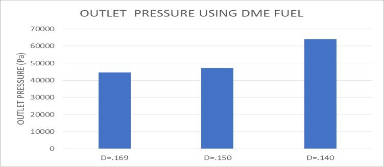
International Research Journal of Engineering and Technology (IRJET) e ISSN: 2395 0056 Volume: 08 Issue: 12 | Dec 2021 www.irjet.net p ISSN: 2395 0072 © 2021, IRJET | Impact Factor value: 7.529 | ISO 9001:2008 Certified Journal | Page1238 Figure6.13:OutletpressurecomparisonusingDMEfuel FromoutletpressurecomparisonchartobtainedfordieselfuelitisevidentthatmaximumpressureofDMEfuelisobservedfor D=.140followedbyD=.150andminimumforD=.169.
iii.
References:
[6]HengzhouWo,KarlD.Dearn ,RuhongSong ,EnzhuHu ,YufuXu ,XianguoHu,“Morphology,composition,andstructureof carbon deposits from diesel and biomass oil/diesel blends on a pintle type fuel injector nozzle”, TribologyInternational91(2015)189
i.
ii.
Conclusions
InthecurrentresearchCFDanalysisoffuelinjectionengineisconductedtodeterminethedesignparametersonthrustforce andstaticenthalpygenerated.Thedesignparametersarerelatedtonumberoffuelinletsi.e.(1,3and5).Thenumberoffuel inlet has significant effect on combustion which in turn effects enthalpy and thus thrust force generation. The detailed conclusionsare: ThecombustionmodelofeddydissipationusedforCFDanalysisoffersimprovedpredictionoffluidflowscomparedto othermodels. Forallsystemconfigurations,thepressuregraphofalldesignsindicatesthehighestpressurevalueinthecombustionzone (1,3and5inlet) Thepressuredecreasesoverthelengthofthefuelinjectionenginetubeandishighestinthecombustionzone. Comparedtothesinglefuelinletconfiguration,astrongquantumofimprovementisfoundinthegenerationofthrustforce usingmultiplefuelinletconfigurations. Comparedto3inletand1inletconfigurations,thefuelinjectionsystemwith5fuelinletdesignshasthemaximumthrust provided. Theproducedstaticenthalpyishighestintheconfigurationof5fuelinletsandlowestintheconfigurationofsinglefuel inlets. Fivefuelinletconfigurationswithamagnitudeof23763kNareusedforthehighestthrustproduced. viii. Thesinglefuelinletconfigurationwithamagnitudeof8876kNisthelowestthrustproduced.
vi.
v.
vii.
[4]V.Lazarev,G.Lomakin,E.Lazarev,“ModelingofInjectionParametersforDieselEngineInjectorNozzleswiththeAdditional PrecisionGuidingInterface”,ProcediaEngineering150(2016)52 60
[2]F.J.Salvador,D.Jaramillo,J. V.Romero,M. D.Rosello,“Usingahomogeneousequilibriummodelforthestudyoftheinner nozzleflowandcavitationpatterninconvergent divergentnozzlesofdieselinjectorss”,JournalofComputationalandApplied Mathematics[3]F.J.Salvador,J.DelaMorena.Martínez López.Jaramillo,“Assessmentofcompressibilityeffectsoninternalnozzleflowin dieselinjectorsatveryhighinjectionpressures”,EnergyConversionandManagement132(2017)221 230
International Research Journal of Engineering and Technology (IRJET) e ISSN: 2395 0056 Volume: 08 Issue: 12 | Dec 2021 www.irjet.net p ISSN: 2395 0072 © 2021, IRJET | Impact Factor value: 7.529 | ISO 9001:2008 Certified Journal | Page1239 [7]ZhixiaHe,WenjunZhong,QianWang,ZhaochenJiang,ZhuangShao,“Effectofnozzlegeometricalanddynamicfactorson cavitating and turbulent flow in a diesel multi hole injector nozzle”, International Journal of Thermal Sciences 70 (2013) [8]132e143TongHaoa,LiYonga,ZhangLonga,LiBaoquanb,“MechanismdesignandprocesscontrolofmicroEDMfordrillingspray holesofdieselinjectornozzles”,PrecisionEngineering37(2013)213 221 [9]ZhixiaHe,ZhengyangZhang,GenmiaoGuo ,QianWang,XianyingLeng ,ShenxinSun,“Visualexperimentoftransient cavitatingflowcharacteristicsinthereal sizedieselinjectornozzle”,InternationalCommunicationsinHeatandMassTransfer 78(2016)13 20 [10]SiminAnvari,HadiTaghavifar,ShahramKhalilarya,SamadJafarmadar ,MohammadTaghiShervani Tabar,“Numerical simulationofdieselinjectornozzleflowandin cylindersprayevolution”,AppliedMathematicalModelling000(2016)1 13 [11]SanghoonLee,SungwookPark,“SprayatomizationcharacteristicsofaGDIinjectorequippedwithagroup holenozzle”, Fuel137(2014)50 59 [12]BoWang,TawfikBadawy,YizhouJiang,HongmingXu,AkbarGhafourian ,XinyuZhang,“Investigationofdepositeffecton multi holeinjectorspraycharacteristicsandair/fuelmixingprocess”,Fuel191(2017)10 24 [13]YangboDeng,HongweiWu,FengminSu,“Combustionandexhaustemissioncharacteristicsoflowswirlinjector”,Applied ThermalEngineering110(2017)171 180 [14]F.J.Salvador,J.Martínez López ,M.Caballer,C.DeAlfonso,“Studyoftheinfluenceoftheneedleliftontheinternalflow andcavitationphenomenonindieselinjectornozzlesbyCFDusingRANSmethods”,EnergyConversionandManagement66 (2013)246 256 [15] E. Delacourta, B. Desmeta , B. Besson, “Characterisation of very high pressure diesel sprays using digital imaging techniques”,Fuel84(2005)859 867