International Research Journal of Engineering and Technology (IRJET) e ISSN: 2395 0056 Volume: 08 Issue: 12 | Dec 2021 www.irjet.net p ISSN: 2395 0072 © 2021, IRJET | Impact Factor value: 7.529 | ISO 9001:2008 Certified Journal | Page96 Perforated Pin Fins Array for Forced Convective Heat Transfer Mohanad Hatem1, Hassan Abdellatif 2, Wadhah Hussein3 1Ph.D Student in Dep. of Mechanical Engineering, Sudan University of Since and Technology, Iraq 2Associate Professor in Dep. of Mechanical Engineering, Sudan University of Since and Technology, Khartoum 3Assistance Professor, Dept. of Mechanical Engineering, Tikrit University, Iraq *** Abstract - High speed multifunctional electronics are being increasingly miniaturized, necessitating more severe temperature management. The use of perforated pin fins to improve the rate of heat transfer in these devices is pinconductionoffins55°Cperforatedfins,temperatureexperimentalExperimentsperforationswasforcedperforatedfindings.increaperforatedeachTheinvestigatedexperimentallyandcomputationallyinthispaper.effectsofthenumberofholesandperforationdiameteronpinareexploredinparticular.TheNusseltnumberforpinsis47percentgreaterthanforsolidpins,anditseswiththenumberofperforations,accordingtotheWhencomparedtosolidpins,thepressuredropwithpinsisalsoreducedby19%.Heattransmissionviaconvectioninapinfinwithcircularholesasheatsinksinvestigatedinanexperimentalresearch.Circularwereamongtheperforationpatterns.wereconductedinaspeciallyplannedandbuiltlaboratory.Atlowpower,itobservedadeclinefrom35to31°Calongthenonperforatedbutatemperaturedropfrom35to29.8°Calongthefins(50W).Temperaturesdroppedfrom120tofornonperforatedfinsand120to38°Cforperforatedatthegreatestpower(600W).Thisisbecausethenumberperforationsperpinhasdecreased,ashastheaxialheatalongthepin.Themodelthatwasutilizedhad16finsandwasmadeoutofAluminumAlloy. Key Words: pin fin, round perforated, forced convection 1. INTRODUCTION Electronic technology has been driven by rapid advancementsinmanufacturing technologyand customer demands to increase component functionality and compactness.Electronicsminiaturizationcausesafasterrate of power dissipation per unit volume. As a result, good thermalmanagementisbecomingincreasinglyimportantin ordertomaintaintheoperatingtemperaturethatensures theefficiencyandreliabilityofelectroniccomponents. Theopposingneedsofmaximizingthermaldissipationrate and limiting pressure drop throughout the system are optimizedinthedesignofheatsinkdevices.Theuseofapin finarraytoaheatsinkdesignisoneofthemostprevalent options Sparrowetal.[1]investigatedtheheatdissipation and pressure drop effects of in line and staggered pin fin arrays.Theheattransmissionandpressurecoefficientsfor staggeredarraysaregreaterthanforin linearrays.Khan's analyticalanalysis[2]cameupwithsimilarconclusions.The lengthwiseandspanwiselayoutsofstaggeredandinlinepins wereoptimizedbyTahatetal.[3.]Bilenetal.[4]measured theheattransportandfrictionofacylindricalfinnedsurface experimentally.Theyfoundthatin lineandstaggeredpinfin arrays provided much more thermal performance than a heatsinkwithoutpins.Morecrucially,forthesameReynolds number, the heat dissipation of staggered pins is 33% greater than that of in line pins, albeit at the cost of increased pressure drop. Soodphakdee et al. [5] used numericalsimulationstoexaminetheimpactofgeometryon finsinin lineandstaggeredconfigurations,andfoundthat circularpinsoutperformedsquarefins,whileellipticalfins outperformed plate fins. The elliptical pin fin has a better heattransfercoefficientatlowReynoldsnumbers(Reh30), whereas the circular pin fin is more effective at higher Reynoldsnumbers(Reh).Pinfinarrayshaveabetterheat transfercoefficientthanplates,buttheyalsohaveahigher pressuredrop[6].Shortpinsarecircularpinswithaheight to diameter ratio of 0.5 4, whereas long pins are circular pinswithaheight to diameterratiogreaterthan4[7].Short pinsareoftenemployedtocoolgasturbineblades,whereas longpinsareusuallyfoundinheatexchangerswithahigh heat transfer coefficient. Vanfossen [8] confirmed experimentally that long pins yielded better heat transfer ratesthanshortpinsinstaggeredpinfinarrays,butatthe costofincreasedpressurelossesandhencehigherpumping power requirements. The majority of research that have shownthatperforationsimprovetherateofheattransferin pinfinarrayshaveonlyemployedasinglepunctureperpin. The metallic foam like porous pins are the logical limit of this characteristic. Indeed, numerical simulations, such as thosebyYang,havebeenconducted. etal.[9]andSeyfandLayeghi[10]haveshownthatfoam like porous pin arrays can boost heat transfer rates by orders of magnitude, owing to their huge surface area to volumeratio. Foam likeporouspins,ontheotherhand,maybeunsuitable sincetheyarereadilycontaminated,leadingtoclosedpores andlowerefficiency.Regardless,researchonfoam likepins suggests that the number of holes per pin may be a key elementincontrollingheattransmission.Theimpactsofpin geometry and combinations have been investigated by several researchers. [11, 12] The magnitude of the recirculatingflowbehindthepinshasasubstantialimpact onthelocalrateofheattransfer,accordingtoMeindersetal. Saraetal.[13]foundthatincreasingthesizeofperforation rather than the number of perforations can improve heat transfer effectiveness for a given porosity. According to ShaeriandYaghoubi's[14]numericalsimulations,therateof heattransferinperforatedfinsissubstantiallygreaterthan in solid fins due to the increased surface area to volume

1.1 Previous Studies Fins, which help with heat transfer, are becoming increasingly popular. Fins composed of anisotropic composites,porousmedia,andperforatedandinterrupted platesaresomeofthenewdesignideasthathaveemerged as extended surface technology advances (Bayram and Alparslan,2008).Theoptimizationoffinsizeiscriticaldue totheneedforlightweight,compact,andcost effectivefins. Asaresult,finsmustbeconstructedtoremovethemostheat withtheleastamountofmaterial,easingfinproduction(Al EssaandAl Hussien,2004).Finshapeoptimizationhasbeen studiedextensively.Otherstudieshaveusedformalterations toenhancetheheattransferareaand/ortheheattransfer coefficient by removing some material from the fins to producecavities,holes,slots,grooves,orchannelsthrough thefinbody(Elshafei,2010). Theusageofinterruptedsurfacesinavarietyofpatternsisa popular heat transfer augmentation strategy. The interruptionisdesignedtoboosttheheattransfercoefficient of the surface area by encouraging surface turbulence (Kutscher, 1994). Non flat surfaces exhibit natural convectioncoefficientsthatare50%to100%higherthan flat surfaces, according to the study (Chung and Layer, 1993). Many other researchers have observed a similar trend for interrupted, perforated, and serrated surfaces, attributingtheimprovementtotherestartingofthethermal boundarylayeraftereachinterruption,indicatingthatthe increaseintheconvectioncoefficientismorethanenoughto compensate for anyarea lost(Elshafei,2010). Fora given profile area, the concave parabolic profile of a straight fin offers greatest heat dissipation (Malekzadeh et al., 2006). Rectangularfinswereemployedinmostapplicationstosave productioncosts.Theubiquitoususageofrectangularfins forheatexchangersnecessitatesaknowledgeofconvection dynamics and a forecast of rectangular fin heat transfer performance. Flow and heat transfer are typically used to study these characteristics at the same time (Suksangpanomrungetal.,2007).Mousa(2000)investigated
International Research Journal of Engineering and Technology (IRJET) e ISSN: 2395 0056 Volume: 08 Issue: 12 | Dec 2021 www.irjet.net p ISSN: 2395 0072 © 2021, IRJET | Impact Factor value: 7.529 | ISO 9001:2008 Certified Journal | Page97 ratio.Furthermore,thetemperaturedifferentialbetweenthe topandbottomsurfacesofperforatedpinsissmallerthan thatofsolidpins,anditshrinksasthenumberofholesper pin increases. They also discovered that solid fins had a substantiallygreateroveralldragcoefficientthanperforated fins,owingtothefactthatsolidfinsmakefarbiggerwakes thanperforatedpins. Theimpactofthenumberofholesandperforationdiameter on heat transfer and flow characteristics appears to be lacking in experimental and computational studies on staggered,circular,longpinfinarrays.Thecurrentresearch describes an experimental and computational analysis of steady state,incompressibleforcedconvectiveheattransfer insolidandstaggeredperforatedpinfinarraystoaddress thesechallenges.Theimpactsofthenumberofperforations, N, and perforation diameter, DP, were investigated using three dimensional (3D) Computational Fluid Dynamics (CFD)simulations.
1.2 Problem Statement. Heatproductioninmanyindustrialapplicationscanleadto overheating and, on rare occasions, system failure. Heat sinksthatareefficientarecritical tosolvingthisproblem. Forced convection from these devices is one of the considered cooling solutions, and it played a key role in preservingtheirconsistentperformance.
Theheattransmissionoftheperforatedfinswasfoundtobe higherthanthatofthenon perforatedfins. Increasesintheheattransfercoefficientandeffectiveheat transfer surface area can improve heat transmission from extendedsurfacesforagivenfinmaterial,basetemperature, and ambient temperature (Shaeri and Yaghoubi, 2009). Surfaceroughnessenhancedtheheattransfercoefficientof the fin surface, resulting in more turbulence. In terms of surface area, there are numerous approaches in the literature for increasing the effectiveheattransferarea of fins(AbdullahandMohammed,2009).Thegoalofthiswork is to see how increasing the number of holes affects temperature distribution, heat transfer rate, and heat transfercoefficient.
2. Experimental Setup. Fin optimization has become a prominent concern for fin designduetoadvancementsinheattransferequipmentsuch asheatsinksusedinelectronicdevicesandothersystems. Finoptimizationisusuallydoneinoneoftwoways.Thefirst istoreducethevolumeormassrequiredforagivenquantity of heat dissipation, while the second is to increase heat dissipationforagivenvolumeormass.Finsarecommonly employedinheat transferdevicestoincreaseheattransfer betweenamainsurfaceandthesurroundingfluid.
Heat exchanger fins come in a variety of forms and sizes, ranging from rectangular, square, cylindrical, annular, tapered, or pin fins to a mix of geometries. The plate fin surfaces'finsareregularlychoppedintopiecesorotherwise disrupted ina varietyof ways.These changesare madeto enhancetheheattransfercoefficientand,insomecases,the heat transfer area. The alterations are made by removing portion of the fin's material to create cavities, holes, slots, grooves, or perforations in the fin's body. Fin size optimization is critical due to the increased demand for lightweight,compact,andcost effectivefins.
thethermalperformanceofahorizontalrectangularfinwith ahomogeneouscross sectionalareaandfourverticalbody perforation patterns running the length of the fin. Triangular, square, round, and rectangular holes were amongthedesignsstudied.Naturalconvectionwasutilized toanalyzethesepatternsusingthefiniteelementmethod.
International Research Journal of Engineering and Technology (IRJET) e ISSN: 2395 0056 Volume: 08 Issue: 12 | Dec 2021 www.irjet.net p ISSN: 2395 0072 © 2021, IRJET | Impact Factor value: 7.529 | ISO 9001:2008 Certified Journal | Page98
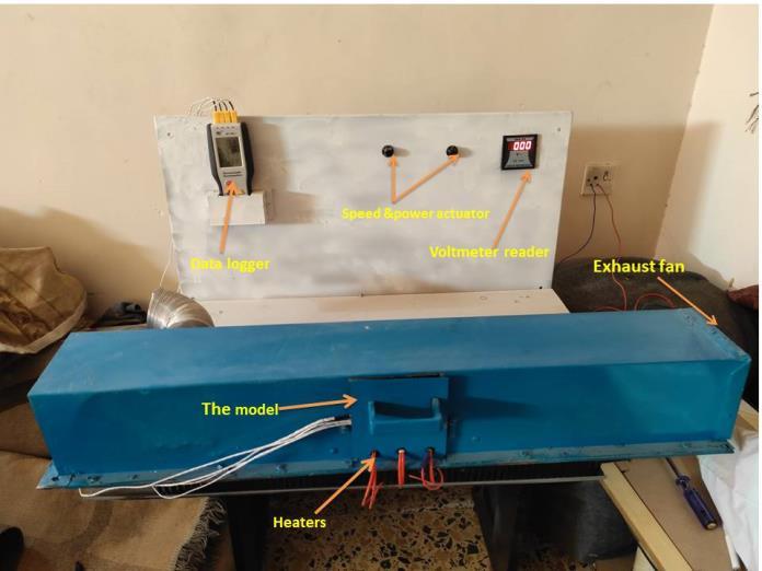
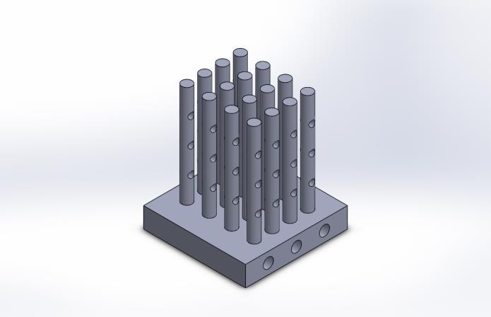
Figure.2 model of perforations
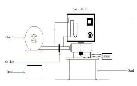
2. Test section (heat sink): a soled brass sheet of certain dimensionsischosenfortesting,andtheworkoftheholes insidethesheetisheatedbyheatingelementsgivenpower. Connectingpinfinsconstructedofaluminumwithprecise dimensions,includingsolidandperforatedtheminvarious shapes (patterns such as round, square, and rectangular perforations)onthesheet'soutersurfacetoserveasatest 3.sample.Thermocouples,manometers,apowersupplyregulator, andacomputermakeupthedataacquisitionsystem.
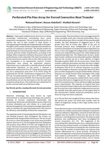
4. Air blower: blows air through the tube that houses the finnedsurfaceheatsink(figure1
1. Main duct (wind tunnel): made of aluminum sheets to evacuateparticulargaseswhilemaintainingaconstantflow ofairtoevaluatethesample.
Figure.1 experimental setup used for study Surfaceinterruptionisrepresentedbyperforatedpinfinsor perforatedfins;thisapproachisusedtocounteractlostarea byincreasingtheconvectioncoefficient.Experimentswere conducted Conduct in a specially planned and built experimental laboratory. The major components of the experimentalsetupareasfollows:


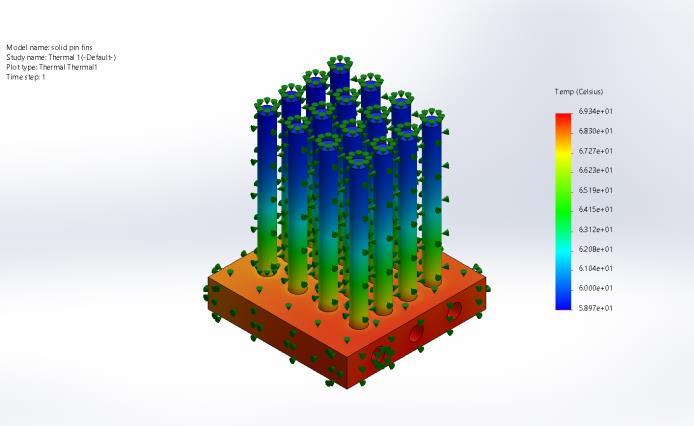
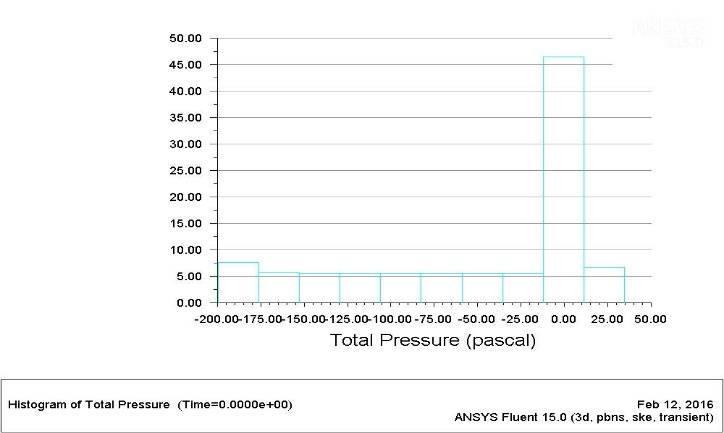
International Research Journal of Engineering and Technology (IRJET) e ISSN: 2395 0056 Volume: 08 Issue: 12 | Dec 2021 www.irjet.net p ISSN: 2395 0072 © 2021, IRJET | Impact Factor value: 7.529 | ISO 9001:2008 Certified Journal | Page99 Ansys.16 was used to simulate the solid and perforated models, with a set flow of air (3m/sec) and varied heat powersprovidedbyheaterelements(3psc10mmdiameter) mountedinthesheetplate'ssidebase. Figure.3 Temperature contour for Perforated Circular pin fin Theperforateddrop shapedpinfinwillimproveinteraction betweentheairflowmediumandthepinfinarrays. When compared to circular and rectangular with holes, this will increaseheattransmission. ThepressurevaluesproducedinANSYSHistogramplotsfor circularinXYplotareshownbelow.TheX axisrepresents pressureamount,whereastheY axisrepresentslocation Figure.4 XY Plot for total pressure drop in a Circular pin fin array


REFERENCES
[1] Yazicioglu, B., “Performance of rectangular fins on a vertical Base in free convection heat transfer”, A Thesis SubmittedtoTheGraduate School ofNatural AndApplied SciencesofMiddleEastTechnicalUniversity,2005.
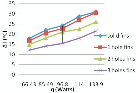
b)Weemployedfourdifferenttypesoffinsinourproject, thereforethethree holefinismoreefficientthantheothers. Convective heat transfer gains 30 to 40% of its value. For variousvaluesofq,thetemperaturedifferencerangesfrom 17 to 31 degrees Celsius for solid fins, 16 to 30 degrees Celsius for one hole fins, 14 to 26 degrees Celsius for two holefins,and12to21degreesCelsiusforthreeholefins.
[2] Cakar, K. M., “Numerical investigation of natural convectionfromverticalplatefinnedheatsinks”,AThesis SubmittedtoTheGraduate SchoolofNatural AndApplied SciencesofMiddleEastTechnicalUniversity,2009.
International Research Journal of Engineering and Technology (IRJET) e ISSN: 2395 0056 Volume: 08 Issue: 12 | Dec 2021 www.irjet.net p ISSN: 2395 0072 © 2021, IRJET | Impact Factor value: 7.529 | ISO 9001:2008 Certified Journal | Page100
Thegraphabovedepictsthetemperaturedifferencesforthe various types of fins utilized in this experiment. When compared to other fins, the temperature differential for threeholesfinsislower.Asaresult,therewillbeincreased convectiveheattransmission.
[3] Tari, I. and Mehrtash, M., “Natural convection heat transfer from inclined plate fin heat sinks”, International JournalofHeatandMassTransfer2013,56,pp.574 593.
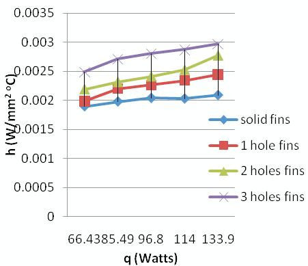
Figure 6: Graph between ‘q’ on X axis and ‘h’ on Y axis
a) Perforated pin fins transmit more convective heat than solidpinfins.Asaresult,wemayemployperforatedfinsina varietyofapplicationsthatwouldnormallyneedsolidfins. Withmoreholesandalargersurfacearea,thetemperature differentialbecomesmoresignificant.
ChangethepingeometryanduseDrop shapedpinfinstofix thisproblem.Themajorbenefitofdelayingtheseparation and reattaching the flow thereafter is the reduction in pressureloss,whichismostlyduetofrictionaldraginthe case of drop pins. This demonstrates that lowering the pressuredropimprovesheattransmission.
Figure 5: Graph between ‘q’ on X axis and Temperature Difference 'ΔT' on Y-axis
The dissimilarity of the h with regard to q, i.e., Qconv, is showninFigure.6.Finsofallkindsarewelcome.Thevalueof h fluctuates from 0.00189748 W/mm2oC to 0.00297 W/mm2oC in this case. This illustrates that when the perforationvalueofhgrows,sodoesthevalueofh.
5. CONCLUSIONS Theresultsofthisexperimentshowthat:
4. Result and Discussion. Differentobservationsare made,suchastheheatinputq, i.e., Qconv. The average temperature across the fins in W. Tm1in°CmeanoutsidetemperatureTm2in°C,temperature differenceTin°C,andhheattransferrateinW/mm2°Cfor solidpinfins,onewholepinfin,twoholespinfin,andthree holespinfins;theresultshowsthatheattransferincreases with the number of perforations; when solid fins are comparedtothreeholespinfins,hincreasesbyabout30to 40%.Inaddition,asthenumberofperforationsincreases, thetemperaturedifferentialreduces.Thisdemonstratesthat alittletemperaturedifferentialresultsinalargeamountof heattransfer
Thepressurefluctuateswiththeplacementsofthepinfin array in a rectangular duct with forced air supplied by a blowerforheattransfer,asshowninthediagramabove.The heater with a heat flux of 5000W/m2 heated the pin fin array, and heat transmission proceeded via forced convection. The perforated round pins appear to have a greaterseparationzoneintheback,whichisdefined by a very low velocity, suggesting the discontinuity of the flow streamlinesandtheflowcirculationdownstreamofthepins.
[7]BaskayaS.,Sivrioglu,M.,Ozek,M.“Parametricstudyof naturalconvectionheattransferfromhorizontalrectangular finarrays”,Int.J.ThermalSci.,2000,39,pp.797 805.
[9]Yazicioglu,B.andYuncu,H.,“Acorrelationforoptimum fin spacing of vertically based rectangular fin arrays subjectedtonaturalconvectionheattransfer”,J.ofThermal ScienceandTechnology,2009,29(1),pp.99 105.
[13] Saad, M. J., “Effect Orientation on Performance of Longitudinal (Trapezoidal) Fins Heat Sink Subjected to NaturalConvection”,AnbarJournalofEngineeringSciences, 2009,2(2).
[6]Yuncu,H.andAnbar,G.,“Anexperimentalinvestigation onperformanceofrectangularfinsonahorizontalbasein freeconvectionheattransfer”,HeatMassTransfer,1998,33, pp.507 514.
[17] Kharche, S. S., Farkade, H. S., “Heat Transfer Analysis through Fin Array by Using Natural Convection”, InternationalJournalofEmergingTechnologyandAdvanced Engineering.,2012,2(4),pp.595 598.
International Research Journal of Engineering and Technology (IRJET) e ISSN: 2395 0056 Volume: 08 Issue: 12 | Dec 2021 www.irjet.net p ISSN: 2395 0072 © 2021, IRJET | Impact Factor value: 7.529 | ISO 9001:2008 Certified Journal | Page101
[15] Fahiminia, M., Naserian M. M., Goshayeshi, H. R., Majidian, D., “Investigation of Natural Convection Heat Transfer Coefficient on Extended Vertical Base Plates”, EnergyandPowerEngineering,2011,3,pp.174 180. [16] Mahmoud, S.,Al Dadah, R., Aspinwall, D. K., Soo, S. L., Hemida, H., “Effect of micro fin geometry on natural convection heat transfer of horizontal microstructures”, AppliedThermalEngineering,2011,31,pp.627 633.
[10] Harahap, F. and Setio, D., “Correlations for heat dissipation and natural convection heat transfer from horizontally based, vertically finned arrays”, Applied Energy,2001,69,pp.29 38.
[18]Sane,S.S.,Sane,N.K.,Parishwad,G.V.,“Computational analysis of horizontal rectangular notched fin arrays dissipating heat by natural convection”, 5th European Thermal SciencesConference,TheNetherlands,2008.
AUTHORS 1 MOHANAD HATEM FEZEA Ph.D. student in Dep. Of Mechanical Engineering, Sudan University of Since and Technology, Iraq 2. Hassan Abdellatif, Associate professor in Dep. Of Mechanical Engineering, Sudan University of Since and Technology, Khartoum 3. Wadhah Hussein Assistance Professor, Dept. Of Mechanical Engineering, Tikrit University, Iraq
[14] Wadhah, H., Razzaq A., Al Doori, “Enhancement of naturalconvectionheattransferfromtherectangularfinsby circularperforations”,InternationalJournalofAutomotive andMechanicalEngineering,2011,4,pp.428 436.
[11] Harahap, F. and Lesmana, H., “Measurements of heat dissipationfromminiaturizedverticalrectangularfinarrays underdominantnaturalconvectionconditions”,HeatMass Transfer,2006,42,pp.1025 1036.
[5] Yazicioglu, B. and Yuncu, H., “Optimum fin spacing of rectangular fins on a vertical base in free convection heat transfer,”Journalofheatandmasstransfer,2007,44,pp.11 21.
[12]Wankar,V.andTaji,S.G.,“ExperimentalInvestigationof flow pattern on rectangular fin array under natural convection”, International Journal of Modern Engineering Research,2012,2(6),pp.4572 4576.
[8] Naidu, S. V., Rao V. D., Rao, B. G., Sombabu, A., Sreenivasulu,B.,“Naturalconvectionheattransferfromfin arrays experimental and theoretical study on effect of inclination of base on heat transfer”, ARPN Journal of EngineeringandAppliedSciences,2010,5(9).
[19]Kim,T.H.,Do,K.H.,KimD.K.,“Closedformcorrelations forthermaloptimizationofplate finheatsinksundernatural convection”,InternationalJournalofHeatandMassTransfer, 2011,54,pp.1210 1216
[4] Tari, I. and Mehrtash, M., “A correlation for natural convection heat transfer from inclined plate finned heat sinks”,Applied Thermal Engineering, 2013, 51, pp. 1067 1075.
[20]Kim,D.K.,“Thermaloptimizationofplate finheatsinks with fins of variable thickness under natural convection”, InternationalJournalofHeatandMassTransfer,2012,55, pp.752 761