Ms. Naik Ashwini Shankarrao1, Dr. P.B. Ullagaddi2
Abstract- Earthquake is an herbal disaster; it creates sturdy floor actions that affect the structure. Small or vulnerable actions which could or might not be perceptible to humans. Shear partitions and bracings are set up to enhance the lateral stiffness, ductility and minimum lateral displacement, and protection of the structure. Bracing structures and shear partitions are most normally implemented in medium to tall homes to offer the rigidity, strength, and power dissipation required to face up to masses from earthquakes and wind. In this work, two main factors were considered, namely with shear walls and bracings for the ceiling structure. The Flat slab structure is modelled with the ETABS software and analysis for Response Spectrum analysis according to 1893: 2002. The Project work is carried out for (G+8), (G+10), and (G+12) stories of structure and the analysis for 12 different models, Flat slab with shear partitions and Bracing System. From assessment various parameters, the Flat slab with shear Partition effects with the values of Story Displacement and Drift is decreased and the values of Story Stiffness and Shear is better than flat slab with the bracing system. It can be concluded that the flat plate with the wall plate is the highest choice compared to all other models, while a flat slab with bracings remains the second choice.
WITH SHEAR WALL AND BRACING SYSTEM FOR DIFFERENT BUILDING HEIGHTS
1.1 Flat Slab
A flat reinforced concrete slab, also known as a beamless slab,theslabatrestsonceonthecolumn,andtheloadfrom theslabis nowtransferred tothecolumns and thento the foundation. To help the heavy hundreds, the thickness of the plate near the help with the column is increased and the people are called drops or columns. they usually come withenlargedheadsknownascolumnheads.
COMPARATIVE FLAT SLAB
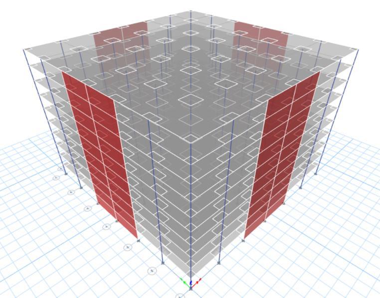
1.2 Shear wall
Key Words: FlatSlab,ShearWall,BracingSystem,Seismic Loads,E TABS.
The shear wall is a structural element used to withstand lateralforcesdesignedtowithstandin plane.lateralforces, commonly wind and seismic hundreds. Withstands hundreds from the cantilever. In different words, wall panels are vertical factors of the horizontal pressure resistance system. In this work RC type of shear wall is used. RC shear partitions are extensively utilized in medium high houses for providing the lateral force, the rigidity and the current dissipation functionality are required.tostandasmuchaslateralhundredsspringingup fromwindorearthquakes.
ASSESSMENT OF
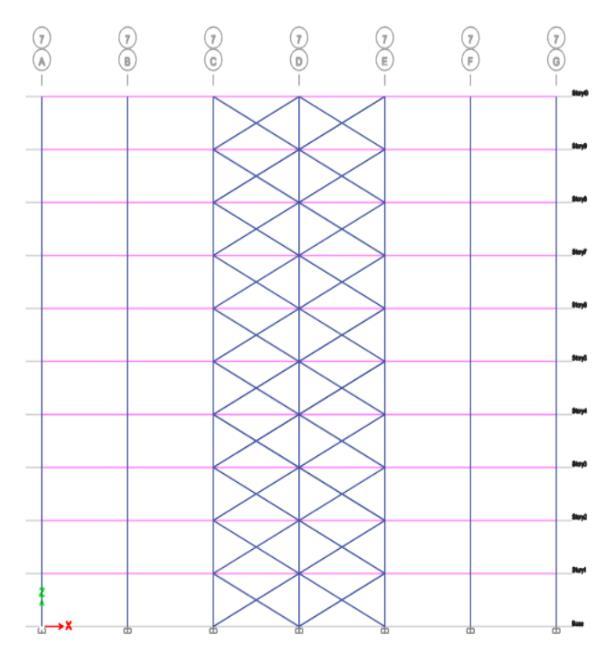
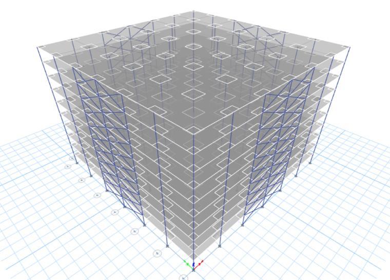
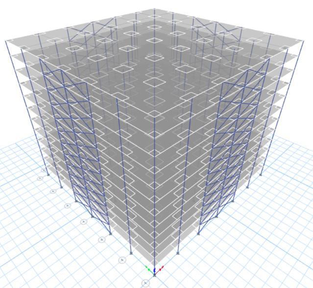
1.3 Bracing Bracing is a construction technique used to improve the overall bearingcapacityof thebuilding. Bracing structures consist of wooden or metal elements that help to evenly distribute the loads and increase the protection of the structure. In this work X type of bracing is used in which two diagonal bars cross each other, it is known as
2Head and Professor, Department of Civil Engineering, Shri Guru Gobind Singhji Institute of Engineering and Technology, Nanded, Maharashtra, India 431606 ***
International Research Journal of Engineering and Technology (IRJET) e ISSN: 2395 0056 Volume: 08 Issue: 12 | Dec 2021 www.irjet.net p-ISSN: 2395-0072 © 2021, IRJET | Impact Factor value: 7.529 | ISO 9001:2008 Certified Journal | Page1184
1.INTRODUCTION
1M. Tech Student, Department of Civil Engineering, Shri Guru Gobind Singhji Institute of Engineering and Technology, Nanded, Maharashtra, India 431606
Theproblemofthearea in cityregionshasexpandedthe vertical improvement including the low rise, high rise, andtall building.Ingeneral,the framed structure isused for the construction of such buildings. The framed structure is subjected to vertical in addition to lateral loads. The lack of framed action in the flat slab structure results in instability in the structure in the seismic zone. Thus, such structures are greater vulnerable to earthquake loads. So, there's a want to carry out the seismic evaluation of the flat slab structure. Thus, the buildings that are designed for vertical loads may not standforthelateral loadsandcanfail fortheduration of anearthquake.Inmany earthquakesinclinedregions,the buildings had been failed which aren't designed for earthquake loads. Thus, all this situation made the seismic evaluationofthestructure ofhigh qualityimportance. The flatslabconstructiontechniqueisthesedaysishavingease in India. Due to many improvements consisting of the benefit of construction, the time required for construction andclearerfloortofloorheightduetotheabsenceofbeam has expanded using the flat slab structure. By combining the flat slab structures with some structural factors can show good results. The structural addition including shear wallandbracingcanbeusedwiththestructure.Sixmodels of the flat plate with shear partition and flat slab with bracing (G+8), (G+10) &(G+12) storied buildings are designed and completed response spectrum analysis. In thisworkshear,wall,andbracingsystemsofstructuresare takenattentionandachievedforlateralforces.

story building(3DView) 3:
International Research Journal of Engineering and Technology (IRJET) e ISSN: 2395 0056 Volume: 08 Issue: 12 | Dec 2021 www.irjet.net p ISSN: 2395 0072 © 2021, IRJET | Impact Factor value: 7.529 | ISO 9001:2008 Certified Journal | Page1185 transverse reinforcement or X reinforcement. This reinforcement must have tensile strength, and each reinforcementcanwithstandtransverseforces. 2. OBJECTIVES
To
systems. [4] To
structures with
3. MODELLING The
[1] examine and design flat plate shear analyses design flat slab structures know the seismic behavior of structures having shearwallandbracing knowthebestsuitablearrangementsystem the structurewhetheritmaybeshearwallandbracing. methodology flat plate with shear
consistsofthemodelingandevaluation of the structure. Modelling of the
partitions & bracing building is achieved by using ETABS 2018Software. 3.1 Structural Data Used Table 1: Preliminaryassumeddata
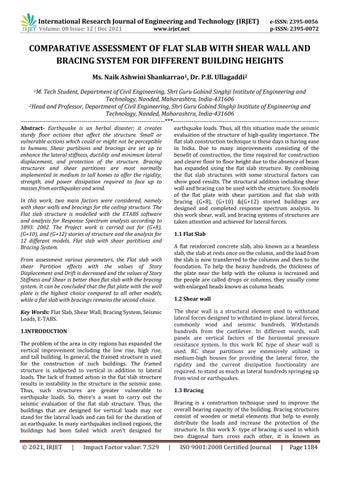
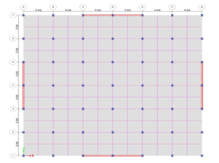
Fig 1: Flatslabwithshearwallhaving(G+8)storybuilding (Plan
Fig FlatSlabwithShearWallhaving(G+8) FlatSlabwithShearWallhaving(G+10) Flatslabwithshearwallhaving(G+10)
with bracing system arrangements for different building heights. [3] To
to
and
View)
story Sr.No. Content Description 1 BuildingStories G+8,G+10,&G+12 2 StoryHeight 3m 3 GradeofConcrete M 30 4 SteelGradefor (MainBar) Fe550 SteelGradefor (ConfinementBars) Fe500 5 ColumnSize: 450x600 6 FlatslabThickness 250mm(M 30,Fe550) 7 Bracing ISMB500oftypeX bracing 8 DeadLoad 6.25KN/m 9 Zone ZoneIICity)(Hyderabad 10 ZoneFactor 1 11 SiteType (TypeII)Medium Soil 12 ImportanceFactor (I) 1.5 13 ResponseFactorreduction 5(SMRF) 14 WindLoad IS875(PartIII) 15 BasicWindSpeed (Vb) ZoneII=44m/sec 16 WindCo efficient forWindward 0.8 WindCo efficient forLeeward 0.5
2:
story building(PlanView) Fig 4:
partition arrangements for different structure heights. [2] To
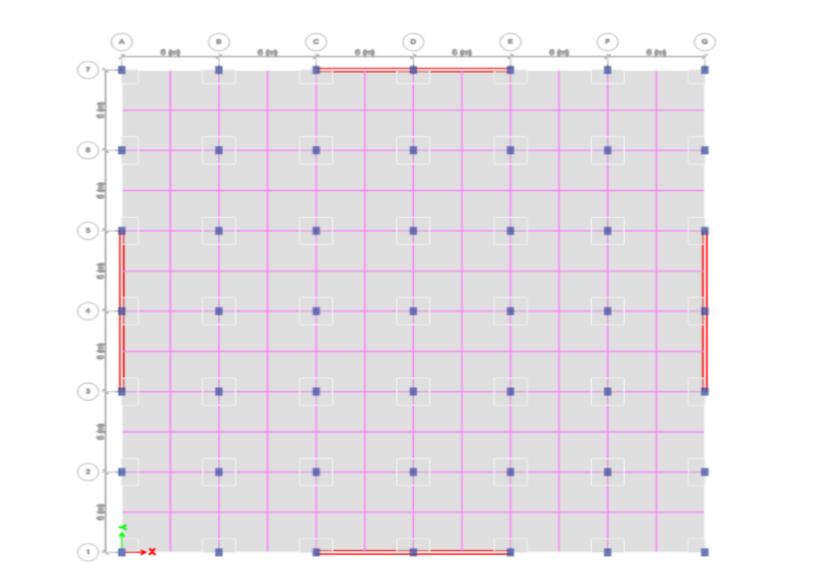
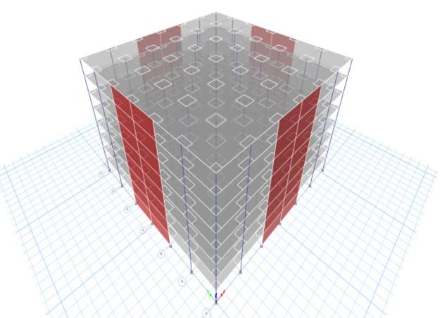
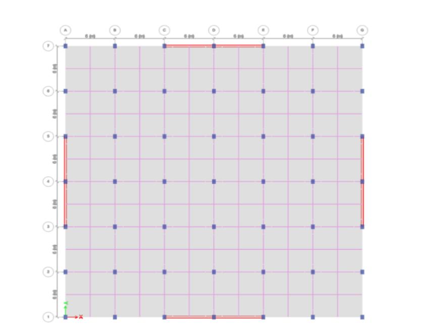

Fig 9: Flatslabwithbracinghaving(G+10)story building(PlanView)
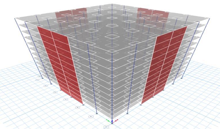
Fig 6: Flatslabwithshearwallhaving(G+12)story building(3DView)
Fig 5: Flatslabwithshearwallhaving(G+12)story building(PlanView)
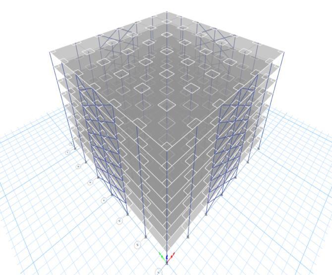
Fig -8: Flatslabwithbracinghaving(G+8)storybuilding (3DView)
International Research Journal of Engineering and Technology (IRJET) e ISSN: 2395 0056 Volume: 08 Issue: 12 | Dec 2021 www.irjet.net p ISSN: 2395 0072 © 2021, IRJET | Impact Factor value: 7.529 | ISO 9001:2008 Certified Journal | Page1186 building(3DView)
Fig 7: Flatslabwithbracinghaving(G+8)storeybuilding. (PlanView)
Anoverallof6modelsofsystemsisusedforthedynamic evaluation of the use of the response Spectrum Method. The Code used is IS1893 part I 2016 for the response Spectrum Method, from which the outcomes of Story Displacement, Storey Shear, Story Drift, & Story Stiffness forseismiczoneIIareobtained.
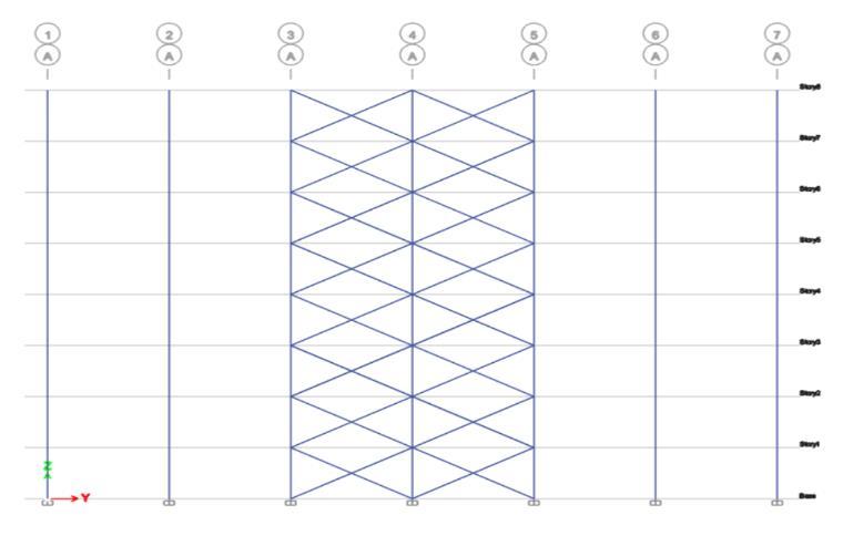
Fig 12: FlatslabwithbracinghavingG+12story(3D View)
STOREY
International Research Journal of Engineering and Technology (IRJET) e ISSN: 2395 0056 Volume: 08 Issue: 12 | Dec 2021 www.irjet.net p ISSN: 2395 0072 © 2021, IRJET | Impact Factor value: 7.529 | ISO 9001:2008 Certified Journal | Page1187
The above graph shows that maximum displacement occurs for the structure that a bracing system has due to stiffness or resistance to lateral forces high, if we comparethisstructurewithshearwall.Wecanseethere is a difference between storey displacement of the shear wallandbracingsystem,forexampleatstorey8thevalue of storey displacement for bracing is maximum i.e., 13.141mm and for shear wall i.e.,5.494mm A flat slab with a shear wall structure is more desirable than a flat slabwitha bracingstructurebecausestorydisplacement isfoundtobeless. MM NO'S DISPLACEMENT
The present work carried out on the comparative investigation of the construction of flat slabs with shear wall and bracing systems for different Building heights.
4. ANALYSIS RESULTS
Fig 11: Flatslabwithbracinghaving(G+12)story building(PlanView)
4.1. Storey Displacement for (G+8): Fig 13: StoryDisplacementfor(G+8)storybuilding
14121086420
STOREY
Fig -10: Flatslabwithhaving(G+10)storybuilding (3DView)
Bracing Shearwall

The above graph shows that maximum displacement occursforthestructurethatabracingsystemhasdue to stiffness or resistance to lateral forces high, if we compare this structure with shear wall. We can see there is a difference between storey displacement of the shear wall and bracing system, for example at storey10thevalueofstoreydisplacementforbracing is maximum i.e., 18.171mm and for shear wall i.e.,10.903mm A flat slab with a shear partition structureismoredesirablethanflatslabwithbracing structure because story displacement is found to be less.
Storey Displacement for(G+10)
International Research Journal of Engineering and Technology (IRJET) e ISSN: 2395 0056 Volume: 08 Issue: 12 | Dec 2021 www.irjet.net p ISSN: 2395 0072 © 2021, IRJET | Impact Factor value: 7.529 | ISO 9001:2008 Certified Journal | Page1188 4.2
4.5. Storey Stiffness for (G+10): Fig 17: StoryStiffnessfor(G+10)Storybuilding
The maximum displacement occurs for the structure that a bracing system has due to stiffness or resistance to lateral forces high, if we compare this structure with shear plate. We can see there is a difference between storey displacement of the shear partitionandbracingsystem,forexampleatstorey12the value of storey displacement for bracing is maximum i.e.,23.73mm and for shear partition i.e.,15.09mm. A flat slab with a shear wall structure is more desirable than a flat slab with a bracing structure because story displacementisfoundtobeless.
20181614121086420MM STOREY NO'S DISPLACEMENT Shear Wall Bracing 2520151050MM Storeyno's Displacement Bracing ShearWall 181614121086420KN/M Millions STOREY NO'S STOREY STIFFNESS Bracing Shear Wall 1614121086420MillionsKN/M STOREYNO'S STOREYSTIFFNESS Bracing ShearWall
4.4. Storey Stiffness for (G+8): Fig 16: StoryStiffnessfor(G+8)storeybuilding The above graph shows, maximum stiffness of the structure having flat slab with shear wall at story 1, i.e 16075530.37 KN / M and the minimum stiffness of the structure having bracing system at storey 1, i.e., 2661172.347 KN/M. Flat plate with shear partition structure is better than flat slab with bracing building becausestorystiffnessisfoundtobemore.
Fig 14: StoryDisplacementfor(G+10)Storey building
4.3. Storey Displacement for (G+12): Fig 15: StoryDisplacementfor(G+12)Story building
International Research Journal of Engineering and Technology (IRJET) e ISSN: 2395 0056 Volume: 08 Issue: 12 | Dec 2021 www.irjet.net p ISSN: 2395 0072 © 2021, IRJET | Impact Factor value: 7.529 | ISO 9001:2008 Certified Journal | Page1189
The above graph shows that maximum stiffness of thestructurehavingflat platewithshearpartitionat storey 1, i.e., 13972018 KN / M and the minimum stiffness of the structure having bracing system at storey 1, i.e., 2549525.6 KN/M. Flat slab with shear partition structure is better than flat plate with bracingstructure becausestoreystiffnessisfoundto bemore.
Theabovegraphshowsthestorystiffnessfor(G+10) structurewithShearpartition&bracingsystem, that maximum stiffness building having Flat plate with shear partition at storey 1, i.e., 14896681.1KN / M and the minimum stiffness structure having bracing systematstory1, i.e.,2598589.4KN/M.Flatslabwith shearpartitionstructureisbetterpreferablethanflat plate with bracing structure because storey stiffness isfoundtobemore.
4.6. Storey Stiffness for (G+12): Fig 18: StoryStiffnessfor(G+12)StoryBuilding
4.7. Storey Shear for (G+8): Fig 19: StoryShearfor(G+8)StoryBuilding
4 8. Storey Shear for(G+10): Fig 19: StoryShearfor(G+10)StoreyBuilding
Theabovegraphshows,maximumshearofthestructure having flat plate with shear partition at storey 1, i.e., 9.5 KN and the minimum shear of the structure having bracingsystematstorey1,i.e.,2.81KN. Aflatslabwitha shear partition shape is ideal than a flat plate with a bracingshapeduetothefactstoryshearisdiscoveredto bemore. 4.9. Storey Shear for (G+12): Fig -21: StoryShearfor(G+12)StoreyBuilding
The above graph shows that maximum shear building having flat plate with shear partition at story 1, i.e., 17.748 KN and the minimum shear of building having bracing system at story 1, i.e., 4.513 KN. Flat slab with shear wall structure is better than flat slab with bracing structurebecausestoreyshearisfoundtobemore.
151050 Base Storey1 Storey2 Storey3 Storey4 Storey5 Storey6 Storey7 Storey8 Storey9 Storey10 Storey11 Storey12 KN/M Millions STOREY NO'S STOREY STIFFNESS Bracing Shear Wall 20151050 Top Bottom Top Bottom Top Bottom Top Bottom Top Bottom Top Bottom Top Bottom Top Bottom Top Bottom BaseStorey1Storey2Strorey3Storey4Storey5Storey6Storey7Storey8 KN STOREY NO'S STOREY SHEAR Bracing ShearWall 1086420 Top Top Top Top Top Top Top Top Top Top Top BaseStorey1Storey2Strorey3Storey4Storey5Storey6Storey7Storey8Storey9Storey10 KN STOREYNO'S STOREYSHEAR Bracing ShearWall 6543210 Top Top Top Top Top Top Top Top Top Top Top Top Top BaseStorey1Storey2Strorey3Storey4Storey5Storey6Storey7Storey8Storey9Storey10Storey11Storey12 KN STOREYNO'S STOREYSHEAR Bracing ShearWall
4.10. Storey Drift for (G+8): Fig 22: StoryDriftforG+8StoreyBuilding
1)Storydisplacementismostatthepinnacletaleandasa minimum at the bottom of the structures. As the constructing peak increases, the price of displacement furthermoreincreases.
5. CONCLUSION
STOREYNO'S
0.00070.00060.00050.00040.00030.00020.00010
2)Theshapehasthemosttaledisplacementforaflatslab with the bracing gadget in comparison to the flat slab withtheshearwall.
4.11. Storey Drift for(G+10): Fig 23: StoryDriftfor(G+10)StoreyBuilding
The above graph shows, maximum shear of the structure having flat plate with shear partition at story 1, i.e., 5.65 KN and the minimum shear of the structurehaving bracingsystematstorey 1,i.e.,1.89 KN.Aflatslabwithashearpartitionshapeisgreater appropriate than a flat plate with bracing shape due tothefactstoryshearislocatedtobegreater.
0.00080.00070.00060.00050.00040.00030.00020.00010
4.12. Storey Drift for(G+12): Fig 24: StoryDriftforG+12StoreyBuilding
STOREYDRIFT Bracing ShearWall
3) The tale float flat plate with shear partition manufacturing is less than flat plate with the bracing gadget. The price of tale float is most somewhere, near thesignificanttale.Thevaluesoftalefloatare withinthe permissible limit, i.e., now no longer extra than 0.004 instances the tale peak in step with the requirements in stepwithIS1893:2002Part1.
The above graph shows that story drift follows a parabolic direction together with the story height, with the maximum value someplace close to the central story. From the above graphs, it becomes found that story go with the drift of flat slab with shear partition building is less than a flat slab with thebracingsystem.
International Research Journal of Engineering and Technology (IRJET) e ISSN: 2395 0056 Volume: 08 Issue: 12 | Dec 2021 www.irjet.net p ISSN: 2395 0072 © 2021, IRJET | Impact Factor value: 7.529 | ISO 9001:2008 Certified Journal | Page1190
The story drift followsa parabolicdirection together with the story height, with maximum value someplace close to the central story. From the above shows That story float of the flat slab with the bracing deviceisextrathanaflatplatewithshearpartitiondevice the peak of the constructing increases and cost of the storydriftadditionallydecreases.
0.00090.00080.00070.00060.00050.00040.00030.00020.00010
STOREY NO'S STOREY DRIFT Bracing Shear Wall
The above graph suggests that storywaft of the flat plate with the bracing machine is extra than a flat slab with shear partition machine height structure increases,andpricestorywaftmoreoverdecreases.
STOREYNO'S STOREYDRIFT Bracing ShearWall
The analysis of buildings with floors (G + 8), (G + 10), & (G + 12) is carried out with a flat ceiling system with shear partitions and Bracing system, following conclusionsaredrawnfromthestudy:
International Research Journal of Engineering and Technology (IRJET) e ISSN: 2395 0056 Volume: 08 Issue: 12 | Dec 2021 www.irjet.net p ISSN: 2395 0072 © 2021, IRJET | Impact Factor value: 7.529 | ISO 9001:2008 Certified Journal | Page1191
8.SudhirSinghBhaduria.,NitinChhugani., “Comparative Analysis and Design of Flat and Grid Slab System with Conventional Slab System”, International Research Journal of Engineering and Technology (IRJET) Volume 04,Issue08,Aug2017
5)Thestiffnessoftheshapewiththebracinggadget could be very low in comparison to a shape with a shearwall.Withgrowingconstructingpeaktheprice ofthetalestiffnessadditionallydecreases.
6) From the assessment of various parameters, the flat plate with shear partition effects with the values Story Displacement and Drift is decreased and the values of Story Stiffness and Shear is better than flat platewiththebracingsystem.
International Journal of Engineering & Science Research (IJESR),Volume05,Issue07July2015
5. Dr. Uttamasha Gupta., Shruti Ratnaparkhe., Padma Gome.,” Seismic Behaviour of Buildings Having Flat Slabs with Drops” International Journal of Emerging Technology and Advanced Engineering Volume 2, Issue 10,October2012.
4. PradipLandeS.,AniketRautB.,“SeismicBehaviour ofFlatSlabSystems”,JournalofCivilengineeringand Environmental technology, and Advanced EngineeringVolume02,Issue10,October2012.
1. Luo Y. H., Durrani A. et.al., “Seismic Reliability Assessment of Existing R/C Flat Slab Buildings”, American Society of Civil Engineers (ASCE), Volume 10,2015.
2) BIS, IS1893: 2002 (Part I), Criteria for Earthquake Resistant Design of structures, Bureau of Indian standards,FifthRevision.
7)Itcanbeterminated that flat platewiththeshear partition is higher preference as compared to all differentmodels,atthesametimeasaflatplatewith bracingsstaysthesecondonepreference.
6.Rameshkumar H Mali., Shreepad Desai., “Performance of Flat Slabs & Flat Plates in High Seismic Zone with Varying Stiffness” International Research Journal of Engineering and Technology (IRJET), Volume 05, Issue 08,Aug2018.
7.P.Srinivasulu.,A.DattatrayKumar.,“BehaviourofRCC flat slab structure under earthquake loading”
10.Sukanya Sawant.,K.R.Dabhekar., “Seismic Analysisof Flat Slab Structure” International Journal of Science Technology & Engineering, Volume 2, Issue 11 |, May 2016 Standard Codes: 1)BIS,IS456:2000, PlainandReinforcedconcretecode ofpractices,BureauofIndianstandards,FourthRevision.
6. FUTURE SCOPE 1)I have studied only four major Parameters i.e., Story displacement, Story drift, Story Stiffness, and taleshear.Thevolumeofwork undertakenthishave a look at is restricted to comparison of seismic reaction parameters in a constructing with different shearpartitionplacestheusageofdynamicanalysis.
4) The tale shear values of the flat slab with shear wall shapeindicates mostpriceincomparison tothe flatslabwithbracingshape.
7. REFERENCES
9. Md. Samdani Azad., Syed Hazni Abd Gani., “Comparative Study of seismic analysis of multistory buildings with shear walls and bracing systems”, International journal of advanced structures and geotechnicalengineering,vol.05,no.03,July2016
[3]BIS,IS875:1987(PartIII), CodeofPracticefor Wind loadsbureauofIndianstandards.
3. Navyashree K., Sahana T. S., “Use of Flat Slabs in Multi Storey Commercial Building Situated in High Seismic Zone”, International Research Journal of Engineering and Technology (IRJET), Volume 03, Issue08,Aug2014.
2)Theexaminationcanbeextendedthroughinclusive of diverse different parameters inclusive of torsion effectsandsoftstoryeffectsinabuilding.
2. Dr. Rame Gowda M., Techi Tata, “Study of Seismic Behaviour of Buildings with Flat Slab”, International Research Journal of Engineering and Technology (IRJET),Volume03,Issue09,Sep.2016.