1.3 NEED OF BRACINGS
Seismic Analysis of Floating Column & Transfer Girder with & without Bracings Jigar J. Solanki1 , Dr. S. S. Angalekar2
1.INTRODUCTION Earthquake is the most dangerous phenomenon because of its unpredictability and massive devastation power. Depending on the zone in which the particular site is located, treatment is required. Earthquakes in the recent past have raised a number of concerns and pushed us to considerdisaster management. To avoid failureor reduce property loss, it is now necessary to think about a structure from the planning stage to the construction stage.So,asaresult,studyingtheseismicreactionofthese buildingsintheelasticrangeiscritical. A column is a vertical member which is supposed to be startingfromfoundationlevelandtransferringtheloadto the ground. Now a days, in the metro cities, Population is increasing and hence more space is required to provide maximum amenities to the residents living in a structure. But due to the lesser space available, it is a common practice to provide all these amenities inside a structure only.Thesemayincludeprovisionofparkingsystem(Stilt Parking, Stack Parking, Puzzle Parking, Basement Parking), Commercial Offices, Shops, Auditorium, Conference Hall etc. In these units, lesser number of columnsareexpectedfromtheArchitects. To comply the needs of large open space, without or with the minimal use of columns, Floating Columns were introduced. Floating Columns are those which starts from an intermediate floor level instead of foundation level to meetthe requirementofopenstorey.The beamonwhich floatingcolumnrestsiscalledasTransferGirder. This Assembly of floating column and transfer girder creates many problems in a structure. Hence it should be carefullystudied,analyzedanddesigned.
1M.E. Structures Student, Department of Civil Engineering, Sinhgad College of Engineering, Pune, Maharashtra, India 2Associate Professor, Department of Civil Engineering, Sinhgad College of Engineering, Pune, Maharashtra, India ***
International Research Journal of Engineering and Technology (IRJET) e ISSN: 2395 0056 Volume: 08 Issue: 12 | Dec 2021 www.irjet.net p ISSN: 2395 0072 © 2021, IRJET | Impact Factor value: 7.529 | ISO 9001:2008 Certified Journal | Page1155
Reinforced concrete structures have become more common in India in recent years. Horizontal members
1.2 DISADVANTAGES OF FLOATING COLUMN
Key Words: Analysis methods, Braced framed structure, Braced system, Concrete Structure, ETABS 2019, Floating Column, Response spectrum analysis, Seismic load, Single diagonal edge bracing, Transfer Girder,Vbracing,Xbracing,
Thoughfloatingcolumnshavetobediscouraged,thereare manyprojectsinwhichtheyareadopted,especiallyabove the ground floor, where transfergirders are employed, so that more open space is available in the Ground Floor. In the earthquake zones, the transfer girders which are employedhaveto be designedanddetailedproperly with care.Ifthereare nolateral loads,thedesignand detailing isnotdifficult.
1.1 ADVANTAGES OF FLOATING COLUMN
3. There is no continuity with the above and below floors makingitvulnerable.
1. Floating columns are mainly used to fulfil the architecturalrequirementsofastructure.
1.Increasestoreydisplacementinbuildings.
2.TheyAttractseismicforcesextensively.
Abstract Floating Columns are those which starts from an intermediate floor level instead of foundation level to meet the requirement of open storey. The beam on which floating column rests is called as Transfer Girder. This Assembly of floating column and transfer girder creates many problems in a structure. Hence it should be carefully studied, analyzed and designed. Bracings in concrete structures are used because it can withstand lateral loads due to an earthquake, wind etc. It is one of the best methods for lateral load resisting systems. Concrete framed high rise buildings are becoming more common in major cities. Engineers have turned to braced concrete framed structures as a cost effective way to resist seismic loads. In this report, Dynamic Analysis by Response Spectrum Analysis is carried out with G+12 Building having floating columns with different types of bracing systems.
2.PlanonEachFloorcanbevariedasperrequirement.
4. Joints of floating column have to bear large amount of shear force and moment due to sudden coming of earthquake. This may cause crack and damage at the joints.
3. They are very useful when the lower floor has a large span hall having rooms on its upper floors such as hotels, offices,shops,auditoriumetc.

3.TodecidesuitabilityofabovesysteminSeismiczonesII, III,IV,V.
2. MODELLING Foranalysispurpose,16differentmodelsareprepared as 1.follows4models of G+12 Storey building, one with floating column and transfer girder & without bracing and others withX,V&Singleedgediagonalbracinginseismiczone II.
2. 4 models of G+12 Storey building, one with floating column and transfer girder & without bracing and others withX,V&Singleedgediagonalbracinginseismiczone III
3. 4 models of G+12 Storey building, one with floating column and transfer girder & without bracing and others withX,V&Singleedgediagonalbracinginseismiczone IV
(beams and slabs) and vertical members (columns and walls) make up a conventional RC structure, which is supported by ground level foundations. A RC frame is a structure made up of RC columns and connecting beams. The RC frame helps to withstand seismic forces. Earthquake shaking causes inertia forces in the structure, which are proportional to the mass of the structure. Because the majority of the building's mass is concentrated on the floor levels, earthquake induced inertia forces are concentrated there. These pressures move down throughslabs to the beams, beams to the columns and walls, and finally to the foundations, where they are diffused to the earth. The columns and walls of the lower storey encounter larger earthquake generated forcesastheinertiaforcesaccruedownwardfromthetop of the building, and are thus intended to be stronger than thestoreyabove. Structural response can be increased in the structures by introducing steel bracing in the structural system. There are 'n' number of possibilities to arrange steel bracings, suchascrossbracingsX',diagonalbracing'D',and'V'type bracing,KneebracingandNewO gridbracing. Thereactionofbracedframesisresearchedextensivelyin various disciplines of structural engineering. Because of their external load carrying capabilities, these buildings have attracted a lot of attention from researchers. Inter storeydriftmustbemanagedinordertoavoiddamageto structuralandnon structuralelements,hencetheconcrete constructionmustbestrongandstiff.
4. The reduction in lateral displacement is a significant benefit. In this situation, concentric (X) bracing is more effectivethaneccentric(V)bracing.
Followingareseveraltypesofbracingsadopted: (i)SingleDiagonalEdgeBracing (ii)Cross bracingorXbracings (iii)K Bracing (iv)V Bracing (v)O GridBracing
4. 4 models of G+12 Storey building, one with floating column and transfer girder & without bracing and others withX,V&Singleedgediagonalbracinginseismiczone V
1.4 DIFFERENT TYPES OF BRACINGS
1.6 OBJECTIVES
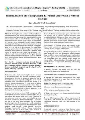
DifferentparametersuchasBaseshear,StoreyDriftRatio, Modal Participating Mass Ratio are compared for these models. The overall plan dimension is 40mx40m. Ground floorheightofthebuildingis4.2mandtypicalfloorheight is3m.
1.7 SCOPE OF STUDY
The floating column and transfer girder captures various problems in structure like Higher time period, creation of soft storey, various irregularities like Mass irregularity, Stiffnessirregularity,Torsionalirregularityetc.Hencethis system needs to be carefully studied, analyzed and designed to avoid collapse of structure and loss of lives under seismic events. So, in this project, G+12 storey building with & without bracings will be analyzed in seismic zones II, III, IV, V by using ETABS 19.0.2 version. Under the seismic analysis, Equivalent static method and Response Spectrum method will be used to compare various parameters like base shear, storey drift, time periods,irregularitiesetc.Aftercomparingtheresults,the suitability of this system will be decided in the various seismiczones.
International Research Journal of Engineering and Technology (IRJET) e ISSN: 2395 0056 Volume: 08 Issue: 12 | Dec 2021 www.irjet.net p ISSN: 2395 0072 © 2021, IRJET | Impact Factor value: 7.529 | ISO 9001:2008 Certified Journal | Page1156
1.Itreduceslateralstoreydisplacement,storeydrift,axial force, and bending moment in columns to a significant 2.extent.Braced frames withstand wind and seismic stresses betterthannon bracedstructures.
3.Itisinexpensive,simpletoerect,andstraightforwardto designtoprovidetheneededstrengthandstiffness.
1.5 ADVANTAGE OF BRACED STRUCTURES
1. To Study Seismic behavior of Floating Column and TransferGirdersystemwith&withoutbracingsinSeismic zoneII,III,IV,V.
2. To compare various seismic parameters in Structure in SeismiczonesII,III,IV,V.
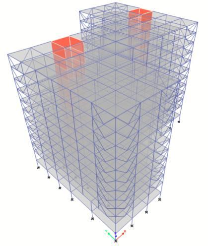
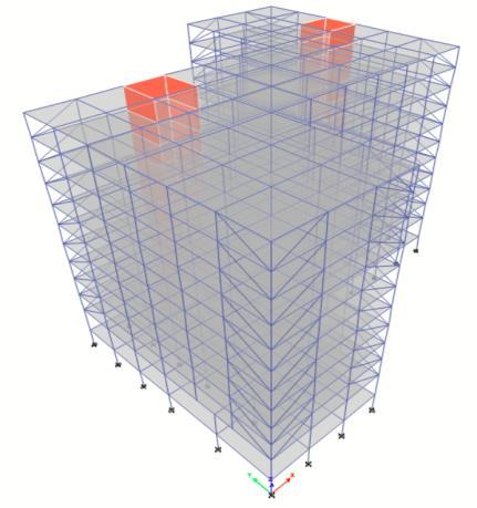
International Research Journal of Engineering and Technology (IRJET) e ISSN: 2395 0056 Volume: 08 Issue: 12 | Dec 2021 www.irjet.net p ISSN: 2395 0072 © 2021, IRJET | Impact Factor value: 7.529 | ISO 9001:2008 Certified Journal | Page1157 3. MODEL DESCRIPTION In this research, Response Spectrum Analysis was performed to study the behavior of floating column and transfer girder with and without bracings. Analysis is carried out by using ETABS 2019 software. Each building is designed using IS 1893:2016, IS 13920:2016 and IS 456:2000. In the following Table, all the parameters of 4 buildingsaresameexcepttheseismiczone. Table 1: Modeldetails Sr. no. Parameter Type/Value 1. StructureType RCCStructure 2. No.ofStorey G+12 3. No.ofmodels 16 4. Ground floor height 4.2m 5. Typicalfloorheight 3m 6. GradeofConcrete M30 7. GradeofSteel Fe500 8. FloorFinish 1.5kN/m2 9. Liveload 2kN/m2 10. Wall Thickness (Internal & External) 150mm 11. WallType AACBlocks 12. WallDensity 10kN/m3 13. SoilType Type I 14. ImportanceFactor 1 15. ReductionResponseFactor 5 16. DampingRatio 0.05 17. Typeofbracing X, V, Single diagonal EdgeBracing 18. SizeofBeam 300mmX600mm 19. Sizeofgirderbeam 1000mmX1250mm 20. Sizeofcolumns 500mmX500mm 21. Size of floating columns 500mmX500mm 4. PLAN & 3D VIEW OF MODELS IN ETABS Following are the 3D pictures of all 12 models with and without bracing which are used for the research work in ETABS. Fig.4.1Planforallframes Fig.4.2Model A,E,I,MwithoutBracinginseismiczone II, III,IV,V Fig.4.3Model B,F,J,NwithX Bracinginseismiczone II,III, IV,V
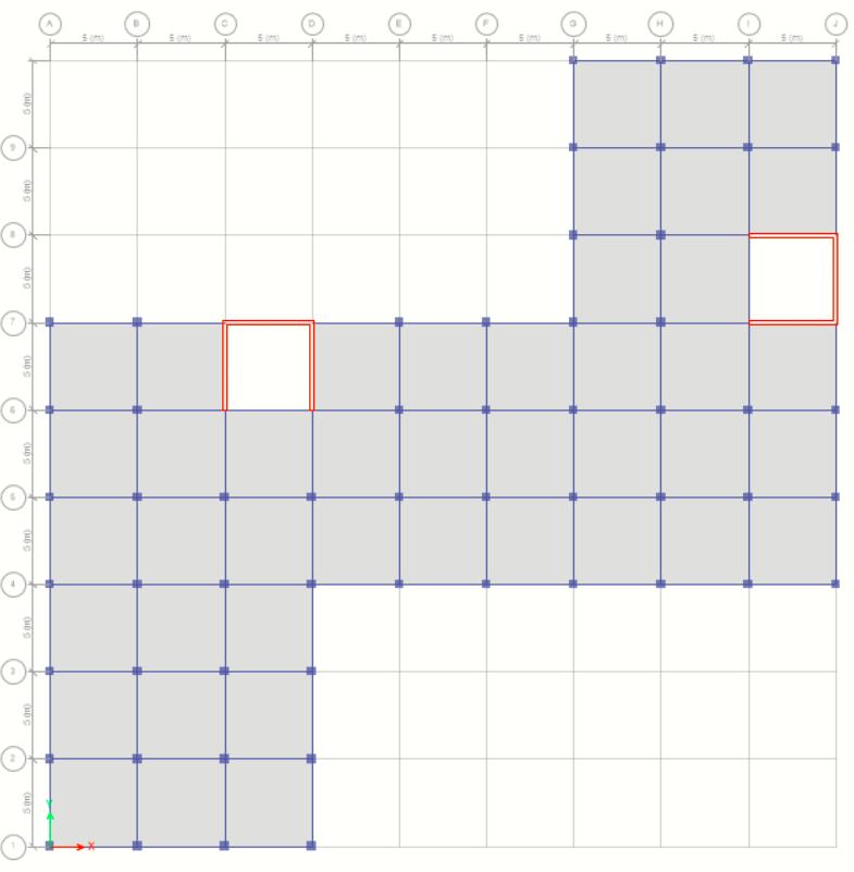
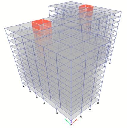
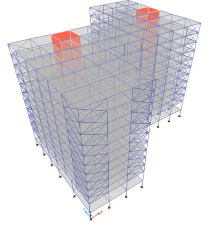
Fig.4.5Model D,H,L,PwithSingleDiagonalBracingin seismiczone II,III,IV,V 3D view of G+12 concrete frames with floating column & transfer girder, without bracing and with X bracing, V bracing and single diagonal bracing are represented in these figures. These models are used for the response spectrum analysis. Section properties are same for all 16 models.Bracingsareprovidedintheendbaysofframesin each Afterdirection.assigning the sectional properties to the frame, 3D models were generated. After that Response Spectrum Analysiswasperformedtostudythebehaviorofstructure. Analysis is carried out by using ETABS 2019 software. After analysis, it was concluded that different bracing systemhelpstodecreasetorsionin1st naturalmode.Also, it is observed that base shear decreases by significant amount when bracings are provided. Bracing system also helpstoreducethestoreydriftinirregularbuilding.
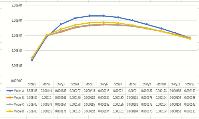
5.1 INTER STOREY DRIFT RATIO
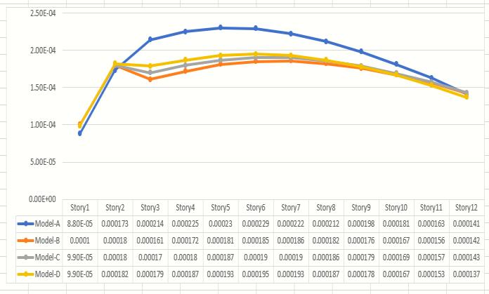
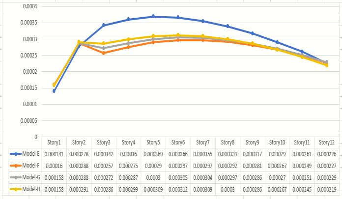
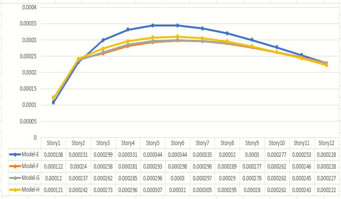
Fig.52Inter storeydriftratioinY Directionformodelsin seismiczone II In Seismic zone II, maximum drift ratio in X Direction is 0.00023 without bracings whereas after providing the bracings, drift ratio reduces to 0.000181 in case of X Bracing. In Y Direction, maximum drift ratio without bracings is 0.000215 which reduces to 0.000183 after bracings are introduced. Hence, X bracing is proved to be themosteffectiveinthesecases.
5. RESULTS AND DISCUSSION Response spectrum analysis was carried out to evaluate theperformanceofRCCbuildingwithfloatingcolumnand transfer girder with & without bracings under the action of lateral forces. After the response spectrum analysis, following results were obtained and are represented in tabularandgraphicalformatandcompared.
Fig.4.4Model C,G,K,OwithV Bracinginseismiczone II, III,IV,V
International Research Journal of Engineering and Technology (IRJET) e ISSN: 2395 0056 Volume: 08 Issue: 12 | Dec 2021 www.irjet.net p ISSN: 2395 0072 © 2021, IRJET | Impact Factor value: 7.529 | ISO 9001:2008 Certified Journal | Page1158
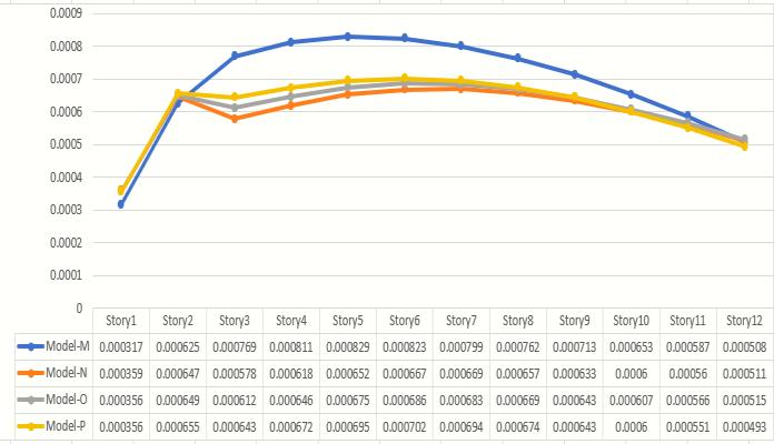
Fig.5.1Inter storeydriftratioinX Directionformodelsin seismiczone II
5.1.1 FOR SEISMIC ZONE-II
5.1.4 FOR SEISMIC ZONE V
Fig.5.4Inter storeydriftratioinY Directionformodelsin seismiczone III In Seismic zone III, maximum drift ratio in X Direction is 0.000369 without bracings whereas after providing the bracings, drift ratio reduces to 0.00029 in case of X Bracing. In Y Direction, maximum drift ratio without bracings is 0.000344 which reduces to 0.000293 after bracings are introduced. Hence, X bracing is proved to be againeffectiveinthiscase.
5.1.3 FOR SEISMIC ZONE IV
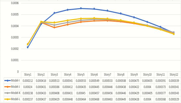
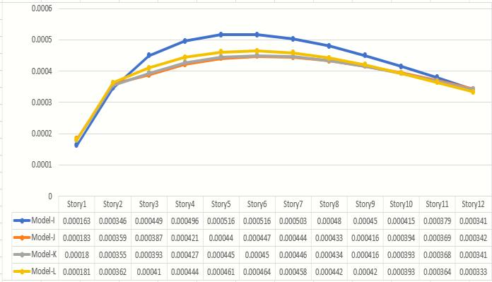
Fig.55Inter storeydriftratioinX Directionformodelsin seismiczone IV Fig.56Inter storeydriftratioinY Directionformodelsin seismiczone IV
International Research Journal of Engineering and Technology (IRJET) e ISSN: 2395 0056 Volume: 08 Issue: 12 | Dec 2021 www.irjet.net p ISSN: 2395 0072 © 2021, IRJET | Impact Factor value: 7.529 | ISO 9001:2008 Certified Journal | Page1159 5.1.2
As observed in table, in Seismic zone IV, maximum drift ratioinX Directionis0.000553withoutbracingswhereas after providing the bracings, drift ratio reduces to 0.000435 in case of X Bracing. Also, In Y Direction, maximum drift ratio without bracings is 0.000516 which reducesto0.000447afterbracingsareintroduced.Hence, X bracingisprovedtobeagaineffectiveinthiscase.
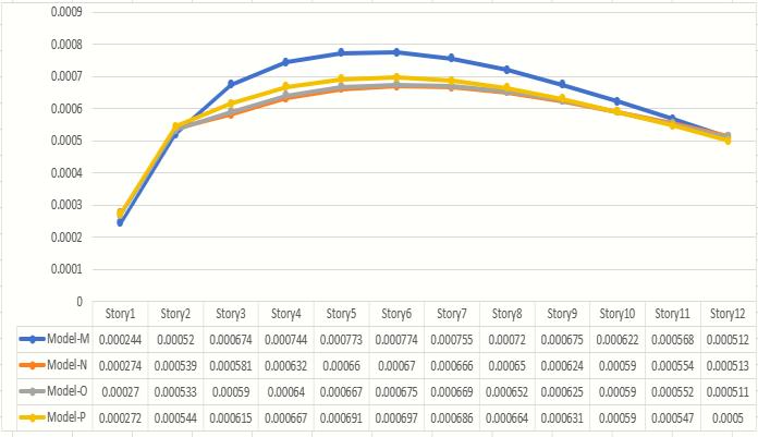
Fig.58Inter storeydriftratioinX Directionformodelsin seismiczone V
FOR SEISMIC ZONE-III
Fig.57Inter storeydriftratioinX Directionformodelsin seismiczone V
Fig.53Inter storeydriftratioinX Directionformodelsin seismiczone III
As observed in table, in Seismic zone V, maximum drift ratioinX Directionis0.000829withoutbracingswhereas after providing the bracings, drift ratio reduces to 0.000652 in case of X Bracing. Also, In Y Direction,
5.3 MODAL PARTICIPATING MASS RATIO 5.3.1 FOR SEISMIC ZONE II
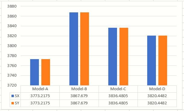
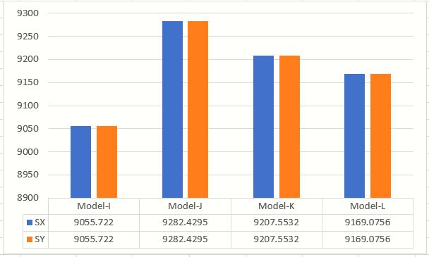
5.2 BASE SHEAR 5.2.1 FOR SEISMIC ZONE II Fig.5.9BaseshearComparisonformodelsinseismiczone II
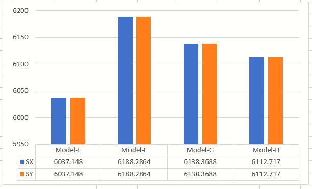
5.2.2 FOR SEISMIC ZONE III Fig.5.10BaseshearComparisonformodelsinseismic zone III
International Research Journal of Engineering and Technology (IRJET) e ISSN: 2395 0056 Volume: 08 Issue: 12 | Dec 2021 www.irjet.net p ISSN: 2395 0072 © 2021, IRJET | Impact Factor value: 7.529 | ISO 9001:2008 Certified Journal | Page1160
maximum drift ratio without bracings is 0.000773 which reduces to 0.00066 after bracings are introduced. Hence, X bracing is useful in all the seismic zones to reduce the driftratio.
In seismic zone IV, the base shear for unbraced structure is 9055.722 kN. After the provision of bracing, the base shear increases to 9282.4295 kN. Hence, the maximum baseshearisobservedinX Bracingsystem.
It can be observed from analysis that base shear for unbraced floating column structure experience a base shear of 6037.148 kN; and for braced system, this value increasesto6188.2864kNincaseofX Bracing. 5.2.3 FOR SEISMIC ZONE-IV Fig.5.11BaseshearComparisonformodelsinseismic zone IV
From the analysis, it was observed that slight torsion is present in first mode for the building without bracings (17.46%). After the bracing is provided, torsion is almost removedin1stmode(2.76%)(reducedbymaximuminX bracingsystem).
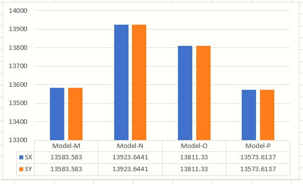
5.2.4 FOR SEISMIC ZONE V Fig.5.12BaseshearComparisonformodelsinseismic zone V
As observed in graph, it can be observed that base shear forthemodelwithoutbracingsystemis3773.2175kNfor X & Y Direction which increases to maximum value of 3867.679kNincaseofX Bracing.
Inseismiczone V,thebaseshearforunbracedstructureis 13583.583 kN. After the provision of bracing, the base shear increases to 13823.6441 kN. Hence, the maximum base shear is observed in X Bracing system in every seismiczone.
ResponseSpectrumAnalysisisusedtostudythebehavior offloatingcolumn transfergirdersystemwith&without different types of bracings in a multistorey RCC framed structure in seismic zone II ,III ,IV, V. Based on the analysis,followingfindingshavebeendrawn: a) FromBaseshear:fig.5.9,5.10, 5.11 & 5.12, it is clear that Base shear unbraced structure is 3773.2175 kN, 6037.148 kN, 9055.722 kN, 13583.583 in seismic zone II, III, IV, V respectively. For braced frame structure, the base shear increases to 3867.679 kN, 6188.2864 kN, 9282.4295 kN, 13923.6441 kN respectively for seismic zone II, III, IV, V This indicates rigidity of the structures improves when various types of bracings are provided specially for
1. In every Seismic zone, sometimes even low rise structures face severe problem, sometimes leadingtoitstotalcollapse,useoffloatingcolumn and transfer girder should be avoided; although provision of bracing can be adopted to control drift, to achieve translational modes in first 2 fundamentalmodeofvibration.
5. ShivamWankhede,M.Shahezad(SeismicAnalysis of Multistory Building with floating Column: A
1. Prof.RupaliGoud(IJSTE InternationalJournalof Science Technology & Engineering | Volume 4 | Issue 1 | July 2017): Comparative study of structures with floating columns and without floating columns under seismic and non seismic forces
3. Mansi Jain, Rupali Goud (study on configurations of floating columns in an asymmetrical irregular RC framed Building under earthquake loading, International Journal of Advanced in Management, Technology and Engineering Sciences)
4. The V type bracing also gave better results in displacement and storey drift when compared to othermodels.
Fromb)irregularstructures.StoreyDrift:fig.5.1,5.2,5.3, 5.4, 5.5, 5.6, 5.7, 5.8, it can be observedthatStoreydriftratioisfoundtobemaximumat nearly mid height of the structure having the values 0.00023, 0.000369, 0.000553, 0.000829 in X Direction in seismic zone II ,III,IV,V respectivelywhen it isunbraced. When the bracings are provided, the storey drift ratio value decreases to 0.000172, 0.00029, 0.000435, 0.000652 in X Direction in seismic zone II ,III, IV, V respectively. This indicates drift of the structures decreasesconsiderablywhenvarioustypesofbracingsare c)provided.ModalparticipatingMassratio: AsperIS:1893 2016,torsionshouldnotbeallowedinfirst 2fundamentalmodesofoscillation.Fromtheanalysis,itis observed that torsion is present in 1st fundamental mode of vibration having the values 0.1746, 0.2171, 0.2171, 0.2171 in seismic zone II, III, IV, V when bracings are not provided. After the inclusion of various types of bracings, it can be observed that torsion is removed from 1st fundamental mode having the values 0.0276, 0.1216, 0.1216, 0.1216 in seismic zone II,III,IV,V respectively. In addition to this, X bracing is proved to be the most effective in every seismic zone as there is very negligible torsioninthefirst2fundamentalmodesofvibration. Following are the concluding remark of the research work:
2. With the application of bracing, the lateral drifts are significantly reduced, and based on these findings,theidealconcentricsystemtousewould betheXbracedsystem,whichhadthebestoverall performance.
6. CONCLUSIONS
2. Trupanshu Patel, Jasmin Gadhiya, Aditya Bhatt (Effect of floating column on RCC building with and without infill wall subjected seismic force, International Journal of Engineering Trends and Technology (IJETT) Volume 47 Number 4 May 2017)
3. Building with X type of bracing is found to be most effective under the action of lateral loads and it is the most suitable type of bracing to increase the seismic performance of the concrete structures.
4. Prof. Nikhil Singla, Er. Ashfi Rahman (Effect of Floating Columns on Seismic Response of Multi Storeyed RC Framed Buildings, International Journal of Engineering Research & Technology (IJERT),Vol.4Issue06,June 2015)
REFERENCES
5. The single diagonal bracing not proved that efficient as compared to X & V Bracings as the reduction in the displacement and drift is very less.
International Research Journal of Engineering and Technology (IRJET) e ISSN: 2395 0056 Volume: 08 Issue: 12 | Dec 2021 www.irjet.net p ISSN: 2395 0072 © 2021, IRJET | Impact Factor value: 7.529 | ISO 9001:2008 Certified Journal | Page1161 5.3.2 FOR SEISMIC ZONE-III, IV, V In Seismic zone III, IV, V, 21.71% mass is participating in twisting action in 1st mode which means torsion is presentin1stmodeinthebuildingnothavinganybracing. But after the bracings are provided, torsion reduces to 12.16%whichmeansitbecomestranslationalmode.Here also,X Bracingisprovedtobethemosteffective.
15. IS 875(part 1):1987 Indian standard code of practice for design loads (other than earthquake) forbuildingsandstructurespartdeadloads unit weights of building materials and stored materials.
17. IS 1893 (Part 1) : 2016. Indian Standard Criteria forEarthquakeResistantDesignofStructures
14. Hardik Bhensdadia, Siddharth Shah (Pushover analysis of RC frame structure with floating column and soft story in different earthquake zones, International Journal of Research in EngineeringandTechnology)
6. Susanta Banerjee, Sanjaya Kumar Patro (Estimation of the Park Ang Damage Index for Floating Column Building with Infill Wall, International Journal of Civil and Environmental EngineeringVol:8,No:6,2014)
10. Mansi Jain, Rupali Goud (study on configurations of floating columns in an asymmetrical irregular RC framed Building under earthquake loading, International Journal of Advanced in Management, Technology and Engineering Sciences)
© 2021, IRJET | Impact Factor value: 7.529 | ISO 9001:2008 Certified Journal | Page1162 Review, International Research Journal of Engineering and Technology Volume 06 Issue 12 Dec2017)
12. ShivamWankhede,M.Shahezad(SeismicAnalysis of Multistory Building with floating Column: A Review, International Research Journal of Engineering and Technology Volume 06 Issue 12 Dec2017)
8. Prof.RupaliGoud(IJSTE InternationalJournalof Science Technology & Engineering | Volume 4 | Issue 1 | July 2017): Comparative study of structures with floating columns and without floating columns under seismic and non seismic forces
9. Trupanshu Patel, Jasmin Gadhiya, Aditya Bhatt (Effect of floating column on RCC building with and without infill wall subjected seismic force, International Journal of Engineering Trends and Technology (IJETT) Volume 47 Number 4 May 2017)
16. IS 875(part 2):1987 Indian standard code of practice for design loads (other than earthquake) for buildings and structures part 2: imposed loads.
7. Hardik Bhensdadia, Siddharth Shah (Pushover analysis of RC frame structure with floating column and soft story in different earthquake zones, International Journal of Research in EngineeringandTechnology)
11. Prof. nikhi Singla, Er. Ashfi Rahman (Effect of Floating Columns on Seismic Response of Multi Storeyed RC Framed Buildings, International Journal of Engineering Research & Technology (IJERT),Vol.4Issue06,June 2015)
International Research Journal of Engineering and Technology (IRJET) e ISSN: 2395 0056 Volume: 08 Issue: 12 | Dec 2021 www.irjet.net p ISSN: 2395 0072
13. Susanta Banerjee, Sanjaya Kumar Patro (Estimation of the Park Ang Damage Index for Floating Column Building with Infill Wall, International Journal of Civil and Environmental EngineeringVol:8,No:6,2014)
18. IS 13920 : 2016 Ductile Design and Detailing of Reinforced Concrete Structures subjected to seismicforces 19. Indian Standard, IS 456 2000, “Plain and Reinforced Concrete Code of Practice,” BIS, New Delhi,India.