3Associate Professor & HOD, Dept. Of Mechanical Engineering, Kuppam Engineering college, AP, India ***
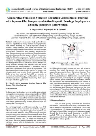
Key Words: Active magnetic bearing; Squeeze film damper, Vibration, Bearing 1. Introduction AMBs are used as bearings however unlike conventional bearingsthereisnocontactbetweenstatorandrotor.AMBs can produce only attractive forces and therefore a closed loop controller is required to maintain stable operation. AMBsoffervariousadvantagesoverrollingelementbearings suchashighspeed,tunability,nowear,nolubrication,and lowerpowerconsumption. The working principle of AMB is shown in Fig 1. An AMB system consists of four essential sub systems: magnetic actuator, controller (digital/analog), power amplifier, and proximityprobe. Whentherotorpositionchangesthesignal fromproximityprobeissenttocontrollerwhichsendserror signaltopoweramplifierwhichinturnsendsthenecessary currenttotheactuatorcoils.Thecoilscreatemagneticflux andattracttherotorbacktoitsequilibriumposition.This real time process helps in levitating the rotor during its operation.
InAMBapplications,eachbearingaxishasapairofpower amplifies. They supply the actuator coils with the current requiredtogeneratetheforcesthatactontherotor.Thus they function between controller and the coils of electromagneticactuator. Eddycurrentproximityprobes, capacitive sensors, inductive pick ups, magnetic pick ups, optical sensors, photo electric sensors, laser type sensors and Hall sensors are the most commonly used sensors in AMB applications(Schweitzer and Maslen, 2009; Tiwari, 2011).Eddycurrentsensorshaveadisplacementrangeof2 mm and possess good frequency response and are most commonlyused. Touchdownbearingsalsocalledauxiliary orbackuporretainerbearingsaremountedatonehalfof AMBairgaptoprotecttheAMBintheeventofpowerfailure orloadsaturation.Duringnormaloperationtheyarenotin contactwiththerotor.
2 Literature Review
Das and Dutt (2010) controlled the transverse vibrationsofaflexiblerotor shaftusingacombinationofPD lawandextendedstateobserver. Basaranetal.(2011)used a H∞ controlleronaflexiblerotorsupportedontworadial AMBsandathrustAMBtocontrolitsvibrationsasitpassed through the first critical speed. Kozanecka et al. (2011) applied AMB as a vibration damper in the torque transmission system to a tail rotor of a helicopter to pass throughthreecriticalspeeds.
International Research Journal of Engineering and Technology (IRJET) e ISSN: 2395 0056 Volume: 08 Issue: 12 | Dec 2021 www.irjet.net p ISSN: 2395 0072 © 2021, IRJET | Impact Factor value: 7.529 | ISO 9001:2008 Certified Journal | Page1095
Abstract - In this work a comparative study of the vibration reduction capabilities of rolling element bearings provided with external damping and that of magnetic bearings is studied. A simply supported rotor system with two discs and subjected to unbalance force is considered. The rotor systemis modeled with Timoshenko beam elements which consider shear deformation and rotational inertia. Theglobalequation of motion of the rotor bearing system is solved in time domain in Mat lab /Simulink environment. Firstly thecaseoftherotor with two discs supported on two rolling element bearings is considered. Three different clearances are considered in SFD and their effect on vibration reduction is studied. Next thetwo rolling element bearings are replaced with two active magnetic bearings with 8 poles each. A parametric study of the effect of changing the value of kp, ki, kd is performed. Time domain wave forms and orbit plots are used to compare the vibration of the rotor systems for the cases with SFDs and AMBs. It has been observed that AMBs are superior to conventional bearing/damper configuration in terms of vibration suppression capabilities thus making them a good choice for industrial applications
1PG Student, Dept. Of Mechanical Engineering, Kuppam Engineering college, AP, India
Fig 1: WorkingprincipleofAMB rotorsystem(taken fromSrinivasetal.,2018)
2Assistant Professor, Dept. Of Mechanical Engineering, Kuppam Engineering college, AP, India
Comparative Studies on Vibration Reduction Capabilities of Bearings with Squeeze Film Dampers and Active Magnetic Bearings Employed on a Simply Supported Rotor System
R Singaravelu1 , Nagaraja S N 2, K Ganesh3


International Research Journal of Engineering and Technology (IRJET) e ISSN: 2395 0056 Volume: 08 Issue: 12 | Dec 2021 www.irjet.net p ISSN: 2395 0072 © 2021, IRJET | Impact Factor value: 7.529 | ISO 9001:2008 Certified Journal | Page1096
ChasaAMBs.levris et al. (2011, 2014) used AMB to study the operationofwornoutjournalbearings.Xuetal.(2016)used a mid span AMB exciter to study the bearing outer race defects of faulty rolling element bearings. Guinzburg and Buse (1995), Baun and Flack (1999) made direct measurementsofreactionforcesactingoncentrifugalpump impellerswiththehelpofretrofittedAMBs.Marshalletal. (2001)madestaticforcemeasurementinAMBsusingmulti point technique based on actuator geometry and control current. Raymer and Childs (2001) measured the force exerted by AMB on rotor using fibre optic strain gages (FOSG)mountedonthemagneticpoles. NordmannandAenisetal.(2004)comparedvariousAMB force measurement techniques such as i s method, reluctance network method, and flux based method using Hall sensors. Zutavern and Childs (2008) identified the parametersofanannulargassealonaflexiblerotortestrig using AMBs. The dynamic forces acting on the rotor were measured using four fibre optic strain gauges and further usedforparameter identification.Kozanecka etal.(2008) used measured gaps and measured magnetic forces to estimationofthebearingdynamicparameters.Tiwariand Chougale(2014)developedalinearregressionalgorithmfor the estimation of AMB dynamic parameters and rotor unbalances for a flexible rotor system levitated on AMBs. Thenumericallyestimatedparameterswerecomparedwith the previously obtained experimental results obtained by Tiwarietal.(2009).TiwariandViswanadh(2015)estimated stiffness constants of AMBs and residual unbalances in a rigid rotor system levitated on AMBs using the numerical responsesobtainedfromaSimulinkTMmodel.
ChasalevrisandPapadopoulos(2015)usedAMBsforearly detectionofshallowcracks(<5%ofshaftradius)inrotating shafts.SinghandTiwari(2015,2016)numericallystudied the behaviour of a rotor bearing AMB system with a breathingcrack.Thevibrationdatathatwaslostonaccount ofusingAMBwascompensatedforbytheuseofcontroller current.BothvibrationandAMBcurrentwereusedforthe purposeofidentifyingcrackparameters.SarmahandTiwari (2018, 2020) identified internal and external damping coefficientsinacrackedrotorsystemsupportedonauxiliary
ZhongandZhu(2013)testedthesteadystateresponseand accelerationresponseofaflexiblerotorusinga2 DOFPID controllerasitpassedthroughthefirstcriticalspeed.The PIDcontrollershowedhigherdampingandbetterstability thanthe1 DOFPIDcontroller.Defoyetal.(2014)compared theperformancesofasimplePID,SISOfuzzyPIDandpolar fuzzycontrollersonaflexiblerotor AMBtestrig. Wangetal.(2014)usedvirtualtrial weightsmethod,which simulate the physical trial weights, for field balancing a magneticallylevitatedflexiblerotorbelowthecriticalspeed. AMBs produce synchronous electromagnetic forces which actastrialweightsinthismethod.DiandLin(2014)applied an all coefficient adaptive control method to stabilize a flexible rotor using an AMB. The performance of the controller was comparable those obtained with the benchmarkµ synthesiscontroller. Zhaoetal.(2015)used modelpredictivecontrol(MPC)methodtostudythestability of a flexible rotor AMB system subject to the input and output constraints. Fang et al. (2015) tested a damping controlmethodona315kWmagneticallysuspendedrotor which reduced the rotor 1X amplitude near the critical EnemarkspeedandSantos(2016)achievedsignificantreduction in1Xvibrationforceofamagneticallysuspendedcentrifugal compressorwithanadaptivenotchfilter. ZhengandFeng (2016) devised an adaptive notch filter to eliminate the current stiffness force of a magnetically suspended centrifugal compressor using a compensation signal. Significant reduction in synchronous vibration force is achievedat30,000rpminexperiments. Lustyetal.(2014,2016)developedaconcentrictwin spool rotorconsistingofahollowouterrotormountedonbearings and coupled magnetically to inner non rotating shaft in a clampedconfiguration.AMBsareactivatedatcriticalspeeds of primary shaft resulting in a coupling between the two rotors that changes the vibration behaviour of the rotor system.Royetal.(2016)implementedacontrollawcalled high frequencyband limitedPDcontrollawonarigidrotor shaftsystem.Thiswasshowntobemoreefficientcompared to PID in reducing the rotor vibration amplitudes. Ranjan andTiwari(2020)usedauxiliaryAMBtointroducevirtual trial unbalances in a flexible rotor supported on rolling element bearings. Influence coefficients were calculated based on these trial unbalancesand were usedto balance rotorbelowitsfirstcriticalspeed. Manietal.(2006),Quinnetal.(2005)usedmultiplescales analysistoestimateacombinationresonanceamongcritical shaft frequencies, shaft rotational speed, and external frequency of AMB excitation. Sawicki et al. (2008), and Sawicki (2009) present similar experimental results on combination frequencies technique. Storozhev (2009) conducted experiments where in cracked rotor was supported/ levitated using AMBs unlike the earlier work where AMB was used as an exciter and not as a support Kasardaetal.(2007)performedexperimentalstudiesonthe useofAMBtoasanactuatorforidentifyingshaftcrack.Litak etal.(2009),Friswelletal.(2010)usedrecurrenceplotsto studytheconditionofacrackedrotor. Sawickietal.(2011a, 2011b)usedcombinationfrequenciestostudytheresponse of a cracked rotor system excited by unbalance force and external AMB force. They used harmonic balance method insteadofmultiplescalesanalysisintheirstudies.Moraiset al. (2012) numerically studied a phenomenon called self healing wherein a mid span AMB was used to control the breathingmechanismofcrack.Thishoweverwasfoundto increasetherotorvibrationlevel.
In
4.2 Force due to stiffness and damping of bearings Rollingelementbearingsareisotropicwithnocross coupled stiffness coefficients. If radk is the radial stiffness of the bearingthentheforcevectorduetostiffnessis 0.5()() 0 iiii ki radbbradbb b kuukuu f (2) Generallytheequivalentviscousdampingofrollingelement bearingsismuchlowerthanthatofjournalbearings.If radc istheradialstiffnessofthebearingthentheforcevectordue todampingisgivenby 0.5()() 0 iiii c radbbradbb b cuucuu f (3) 4.3 Squeeze Film Damper SFDs are commonly used in rotor systems in conjunction witharollingelementbearingforthepurposeofattenuating rotorvibration.Theempiricalrelationsprovidedherearefor the short bearing approximation (Chen & Gunter, 2007). Whentheoilfilmcompletelyfills(2πfilm,nocavitation)the annulusthenthestiffnessanddampingofSFDaregivenby 0K (4)
d)Toperformparametricstudiesonrotor 1byvaryingthe geometricparametersofSFDsuchasclearance,landlength.
3. Objectives Theobjectivesofthepresentworkare
12121212 TT e xzyzyyxx jxxjyy uuu (1) Themass,stiffnessandgyroscopic matricesofshaft,discs are
Besides
Fig
size
e)Toperformparametricstudiesonrotor 2byvaryingthe gainconstantsofAMB(KP,KI,andKD).
4. System Configuration and Mathematical Modeling For the presentstudy two different rotor systems have been considered. Fig 2 shows the simply supported rotor systemwithtwodiscssupportedonrollingelement bearings at either end. Viscous damping is provided by incorporating squeeze film dampers at both the bearing locations.Figure3showsthesamerotor systemsupported onAMBsateitherend. 2: Rotor Bearing SFDsystem. Fig-3:Rotor AMBsystem Shaft and disc model this work Timoshenko beam finite elements have been usedtodiscretizetherotorsystem.Theelementalmatricesof giveninChenandGunter(2007)thatcorrespondtoa complex nodal displacement vector have been used for modeling each finite element. reducing the computationaleffort. given etal.(2010).
f) To perform comparative study from the vibration responsesofrotor 1androtor 2.
International Research Journal of Engineering and Technology (IRJET) e ISSN: 2395 0056 Volume: 08 Issue: 12 | Dec 2021 www.irjet.net p ISSN: 2395 0072 © 2021, IRJET | Impact Factor value: 7.529 | ISO 9001:2008 Certified Journal | Page1097
intheFriswell
c)TobuildtheSimulinkmodelsforrotor 1androtor 2to generateresponsesintimedomain
After conducting a comprehensive survey of literature availableonAMBssomegapshavebeenfoundwhichneedto be explored.a) The comparison of the vibration characteristicsofAMBsandSqueezefilmdampers(SFD)has notbeenaddressed.b)Theidentificationoffaultparameters inthepresenceofmultiplefaultssuchasunbalance,cracks, misalignment,rubshasnotbeeninvestigated.c)Theeffectof AMBinrotorsystemswherelateralandtorsionalvibration iscoupledhasnotbeeninvestigated.
a) To develop the mathematical model a rotor bearing systemsupportedonSFDs(Rotor 1). b) To develop the mathematical model a rotor bearing systemsupportedonAMBs(Rotor 2).
4.1

Theunbalanceforcevectorduetothemasseccentricitiesat thenodallocationsofdiscsis 2jj t unbdmeeef (10) Where e is the disc unbalance eccentricity located at the phaseangle. 4.6 Global Equations of Motion ForthecaseofrotorsupportedonSFDstheglobalEOMin complex form obtained by assembling the sub system matricesisgivenby j unb MuCGuKuf (11) where shaftdisc MMM ; brgSFDshaft CCCC ; brgshaft KKK ; shaftdisc GGG ForthecaseofrotorsupportedonAMBstheglobalEOMin complex form obtained by assembling the sub system matricesisgivenby j unbAMB MuCGuKuff (12) where shaftdisc MMM ; brgshaft CCC ; brgshaft KKK ; shaftdisc GGG 4.7 Simulink Model Eq.(11) is used to build the Simulink model of Rotor Bearing SFD system shown in Figure 4. The responses of bearings,discscanbeplottedusingthetimedomainoutput ofthismodel.LikewiseEq.(12)isusedtobuildtheSimulink modelshowninFig 5.Inadditiontothevibrationresponses atvariousaxiallocationsalongthelengthoftherotor,AMB currentisalsoobtainedfromthemodel. There are various fixed step and variable step solvers available in Simulink library. The choice of the solver dependsuponthenatureoftheequationsbeingsolved.For the present problem Runge Kutte 4th order solver with a fixed time step of 410 s is used to solver Eq.(11) and TheEq.(12).present section dealt with the development of mathematical models for Rotor Bearing SFD system and Rotor AMB system using the elemental matrices of shaft, disc, and bearings. The external forces acing on the rotor system are the unbalance forces generated due to the uneven mass distribution. Simulink models have been developedforRotor SFDsystemandRotor AMBsystemto identify worksdomain.resonancesandgeneratevibrationresponsesintimeTheAMBthatisintegratedwiththerotorsystemonPIDcontrollaw.Thenextsectiondealswiththe
International Research Journal of Engineering and Technology (IRJET) e ISSN: 2395 0056 Volume: 08 Issue: 12 | Dec 2021 www.irjet.net p ISSN: 2395 0072 © 2021, IRJET | Impact Factor value: 7.529 | ISO 9001:2008 Certified Journal | Page1098 3 323/2 (1) RL C C (5) When the oil film partially fills the annulus (π film, cavitation)thenthestiffnessanddampingofSFDaregiven by 3 322 2 (1) RL K C (6) 3 323/22(1) RL C C (7) where istheviscosityofoil,CistheSFDclearance, is theeccentricityratio(e/c;eisthejournaleccentricity), is theangularspeedofrotor,RisSFDradiusandLisSFDland length. The above expressions are valid for the cases of circularsynchronousradialmotionabouttheoriginwithno precession. 4.4 Active Magnetic Bearing The lateral force exerted by the AMB on the rotor at its nodallocationisgivenby 0 sAMBic AMB kuki f (8) where () cpAMBiAMBDAMB itKuKudtKu (9) AMBu isthecomplexrotorvibrationattheAMBlocation, ic is thecomplexAMBcurrentks andkiarethedisplacementand currentstiffnessconstantsofAMB. In the present work PID control law is employed and the valuesofproportionalgain(KP),integralgain(KI),derivative gain (KD) of the controller are taken from Bordoloi and Tiwari (2013). These gain values can be chosen from the pidTuner which is a MATLAB tuning algorithm with a graphicaluserinterface. 4.5 Unbalance Force
parametricstudiesandresultsgeneratedfromtheSimulink models. Fig- 4 : SimulinkmodelofRotor Bearing SFDsystem (rotor 1) Fig 5:SimulinkmodelofRotor Bearing SFDsystem (rotor 1)foridentifyingresonances
5. Results and Discussions
In this section firstly the response of the rotor bearing system without external viscous damping through SFD is studied.Therotorisdiscretizedinto25elements,each20 mminlength.Thenodallocationsofbearingsare(1,21)and those of discs are (6, 21). Table 1 shows the geometric propertiesoftheshaft,discsandbearings.
Table 1: Propertiesofshaft,discs,andbearings
ThecriticalspeedsoftherotorsystemareobtainedfromFig 8whichisthehilbertenvelopeofvibrationinxdirectionthat isobtained by rampingupthe rotor from0 rpmto 12000 rpmatarateof40πrad/sfor10seconds.Itcanbeseenfrom thattheresonantspeedsofrotorarepresentat3090rpm and8234rpm.Theorbitsoftherotoratcriticalspeedsare showninFig 9.
International Research Journal of Engineering and Technology (IRJET) e ISSN: 2395 0056 Volume: 08 Issue: 12 | Dec 2021 www.irjet.net p ISSN: 2395 0072 © 2021, IRJET | Impact Factor value: 7.529 | ISO 9001:2008 Certified Journal | Page1099
Fig 6: SimulinkmodelofRotor AMBsystem(rotor 2) Fig 7: SimulinkmodelofRotor AMBsystemfor identifyingresonances(rotor 2)


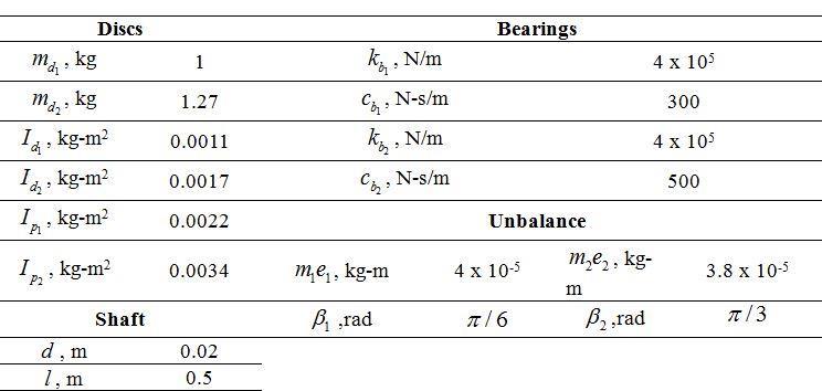
Fig 10: Dampingcoefficientvseccentricityratiofor(a) c=0.1,L=20(b)c=0.125,L=20(c)c=0.175,L=20(d) c=0.1,L=25(e)c=0.125,L=25(f)c=0.125,L=175(c &Linmm)
International Research Journal of Engineering and Technology (IRJET) e ISSN: 2395 0056 Volume: 08 Issue: 12 | Dec 2021 www.irjet.net p ISSN: 2395 0072 © 2021, IRJET | Impact Factor value: 7.529 | ISO 9001:2008 Certified Journal | Page1100
Fig 8:Hilbertenvelopeofrotorvibrationinxdirection fornominalunbalanceatnode 21
Fig 9: Orbitsatvariouslocations(a)Bearing 1 (b) Disc 1(c)Disc 2(d)Bearing 2fornominalunbalance 5.1 Response of rotor system with squeeze film damper (rotor 1) Parametric studies are carried out by varying the radial clearance(125µm,150µmand200µm) andlandwidthof theSFD(20mm,25 mm). A2πoilfilm(nocavitation)is assumedtobepresentaroundtheannulusoftheSFD.The dampingcofficientsarecalculatedfromEq.(5).Thevarious parametersofSFDaregiveninTable2.
Fig-11: Orbitsatvariouslocations(a)Bearing 1(b) Disc 1
Table: 2 ParametersofSqueezeFilmDamper Oilviscosity, ,N s/m^2 5e 3 SFDradius, R ,mm 75 Landwidth, L ,mm 20,25 Radialclearance, c ,µm 125,150,200 Inpractice SFDsoperateat eccentricity ratiosof0.4 0.5. FromFigures10(a)to10(f)itcanbeseenthatforagiven land width with increasing clearance damping coefficent increases. Also it can be seen that for a given amount of radialclearancethedampingvalueincreaseswithincreased land width. Fig 11 and Fig 12 show the orbits at various locations along the rotor length i.e. at the locations of bearing 1,disc 1,disc 2andbearing 2.Itisclearlyevident thathigherdampingcontributestoacleardecreaseinthe size of the orbits. Fig 13 shows the response at disc 2 location for the above six configurations when the rotor acceleratesfromstandstilltobeyondsecondcriticalspeed. Fig 14showsthatasdampingincreasesthecriticalspeeds shifttohighervalues.Theamplitudeofvibrationdecreases initiallywithincreaseindamping.Beyondacertainvalueof dampingtheamplitudeagainincreases.The x displacement withc=14510N s/mis400µmwhereaswithc=28870N s/mthe x displacementis500µm.Thisshowsthatincrease indampingbeyondacertainvaluerigidifiesthesupportand leadstoincreaseinvibration.
(c)Disc 2(d)Bearing 2forc=7430N s/m Fig 12: Orbitsatvariouslocations(a)Bearing 1(b)Disc 1 (c)Disc 2(d)Bearing 2forc=14510N s/m Fig 13: ResponseofvariousSFDconfigurationsatDisc 2 locationfor10cm.gmunbalance
5.2 Response of rotor system with active magnetic bearing (rotor 2) In the next stage parameteric studies are carried out by varyingthegains ,, PIDkkk ofcontrollertoinvestigatetheir effectof the responses.The valuesofAMBgainsandAMB displacement stiffness and current stiffness are given in Table3. Table 3: AMBparametersconsideredforparametric studies Pk N/m, 12000 8000 4000 Ik ,N/A 2000 1000 500 Dk 10 5 3 s k 105210 ik 42.1 FromFig 15itcanbeseenthatwithincreasingproportional gain Pk thecriticalspeedoftherotorsystemshiftstohigher speedsandincreasestheresponseamplitudeaswell.For Pk of400thecriticalspeedanddisc 1amplitudesare1056rpm and 204 microns respectively. Increasing Pk to 12000 increases the respective values to 2045 rpm and 531 microns.
International Research Journal of Engineering and Technology (IRJET) e ISSN: 2395 0056 Volume: 08 Issue: 12 | Dec 2021 www.irjet.net p ISSN: 2395 0072 © 2021, IRJET | Impact Factor value: 7.529 | ISO 9001:2008 Certified Journal | Page1101
Fig 14: ResponseofvariousSFDconfigurationsat1st criticalspeedfor10cm.gmunbalance
Fig 15:SensitivityofRotor AMBsystemto Pk (x displacementatDisc 1)
Fig 19: SensitivityofRotor AMBsystemto Dk (x currentatBearing1) Fig 16 shows the effect of increasing Integral gain Ik .Withincreasein Ik theresponseinitiallyincreaseswith increasing Ik and then decreases. Similar trend can be noticed in the critical speeds with the value shifting from 1068rpmwith Dk of5to1056rpmfora Dk valueof20and then decreasing to 1016 rpm for a Dk value of 20. Fig 17 showsasimilartrendintheAMBcurrentplots.Fig 18shows theeffectofincreasingderivativegain Dk .Asthevalueof Dk incerasesfrom5to20theresponseamplitudedecreases from 17 microns to 11 microns. The corresponding AMB currentincreasesfrom0.97Ato1.4asshowninFig 19.Also amarginalshiftin1stcriticalspeedcanbenoticedfrom1144 rpmto1299rpmandthe2nd criticalspeedshiftsfrom7632 rpmto7832rpm.
Fig 16: SensitivityofRotor AMBsystemto Ik (x displacementatDisc 1) Fig 17:SensitivityofRotor AMBsystemto(x currentat Bearing1) Fig 18: SensitivityofRotor AMBsystemto Dk (x displacementatDisc 1)
6. Conclusions A parametric study has been made to study the effect of incorporating squeeze film dampers and active magneticbearingsinasimplerotorsystemwithtwodiscs. Timoshenkobeamelementsareusedtodiscretizetherotor systemintofiniteelements.Externalforcingduetothemass unbalance present in the discs has been considered. The globalequationsofmotionhavebeenassembledusingthe mass, stiffness, gyroscopic matrices of shaft, mass and gyroscopicmatricesofdiscs.Initiallytheresponseofrotor systemwithnominaldampinghasbeenconsidered.The1st and2ndcriticalspeedshavebeenfoundtobepresentat3090 rpmand8234rpm.Theresponseat1st criticalspeedis322 microns. Next SFDs have been incorporated at bearing locations to introduce external viscous damping. Three differentclearancesandthreedifferentdamperlengthshave beenconsideredforparametricstudies.Ithasbeenshown that damping is linear up to an eccentricity ratio of 0.5. Beyond this it shows significant nonlinearity. From the responseplotsitisfoundthatincorporationofSFDcertainly
International Research Journal of Engineering and Technology (IRJET) e ISSN: 2395 0056 Volume: 08 Issue: 12 | Dec 2021 www.irjet.net p ISSN: 2395 0072 © 2021, IRJET | Impact Factor value: 7.529 | ISO 9001:2008 Certified Journal | Page1102
1. Bordoloi, D.J., Tiwari, R., Optimization of controller parameters of Active Magnetic Bearings in Rotor Bearing Systems, Advances in Vibration Engineering, 12, pp 319 327,2013 2.Basaran,S.,Sivrioglu,S.,Okur,B.,andZergeroglu,E.,2011, “Robust H∞ control of Flexible Rotor Active Magnetic BearingSystem”,6thInternationalAdvancedTechnologies Symposium,Elazig,Turkey,39 43
13. Kozanecka, D., Kozanecki, Z., Lech, T., 2008, “Experimental Identification of Dynamic Parameters for Active Magnetic Bearings”, Journal of Theoretical and AppliedMechanics,46,1,41 50
9.8 Enemark, S., Santos, I.F., 2016, “Feed forward compensation control of rotor imbalance for high speed magnetically suspended centrifugal compressors using a noveladaptivenotchfilter”,JournalofSoundandVibration, Volume366, 1 14 10. Fang, J., Tang, E., Zheng, S., 2015, “Optimum Damping Control of the Flexible Rotor in High Energy Density Magnetically Suspended Motor”, Volume 137, 082505 1 082505 9
6.Chen,W.J.,Gunter,E.J,2007,“IntroductiontoDynamicsof Rotor BearingSystems”,TraffordPublishing,Charlottesville, Virginia,469pages. 7.Das,A.S.,Dutt,J.K.,Ray,K.,2010,“Activevibrationcontrol of unbalanced flexible rotor shaft systems parametrically excited due to base motion”, Applied Mathematical Modelling,Volume34,Issue9, 2353 2369
16.Mani,G.,Quinn,D.D.,Kasarda,M.E.F.,2006,“Activehealth monitoringinarotatingcrackedshaftusingactivemagnetic bearingsasforceactuators”,JournalofSoundandVibration, Volume294,Issue3,454 465
18. Nordmann, R., Aenis, M., 2004, “Fault Diagnosis in a Centrifugal Pump Using Active Magnetic Bearings”, InternationalJournalofRotatingMachinery,10(3),183 191
14.Kozanecka,D.,Kozanecki,Z.,Lagodzinski,J.,2011,“Active magneticdamperinapowertransmissionsystem”,Commun Nonlinear Sci Numer Simulat, Volume 16, Issue 5, 2273
20.Ranjan,G.,Tiwari,R.,2020,“On sitehigh speedbalancing of flexible rotor bearing system using virtual trial unbalancesatslowrun”,InternationalJournalofMechanical Sciences,183,105786
15.2278Litak,G.,Sawicki,J.T.,Kasperek,R.,2009,“Crackedrotor detectionbyrecurrenceplots”,Non destructiveTestingand Evaluation,Volume 24,No.4,347 351
19. Quinn, D. D., Mani, G., Kasarda, M.E.F., Bash, T., Inman, D.J., Kirk, R. G.,2005, “Damage Detection of a Rotating CrackedShaftUsinganActiveMagneticBearingasaForce Actuator Analysis and Experimental Verification”, IEEE/ASMETransactionsonMechatronics,Volume 10,No. 6,640 647
3.Chasalevris,A.C.,Dohnal,F.,Markert,R.,2011,“Symptoms of Misaligned Worn Journal Bearings in Rotor Response under External Excitation by A Magnetic Bearing”, Proceedings of the ASME 2011 International Design Engineering Technical Conferences & Computers and Information in Engineering Conference, IDETC/CIE 2011, August28 31,Washington,DC,USA 4. Chasalevris, A.C., Dohnal, F., Chatzisavvas, I., 2014, “Experimentaldetectionofadditionalharmonicsduetowear in journal bearings using excitation from a magnetic bearing”,TribologyInternational,Volume71,158 167
5.Chasalevris,A.C.,PapadopoulosC.A.,2015,“Experimental detection of an early developed crack in rotor bearing systemsusinganAMB”,InternationalJournalofStructural Integrity,Volume6,Issue2,194 213
21.Raymer,S.G.,Childs,D.W.,2001,“ForceMeasurementsin Magnetic Bearings using Fibre Optic Strain Gauges”,
11. Friswell M.I., Penny, J.E.T., Garvey, S.D., Lees, A.W., DynamicsofRotatingMachines,CambridgeUniversityPress, 1stEdition,March,2010,NewYork,USA 12.Kasarda,M.E.F.,Bash,T.,Quinn,D.,Mani,G.,Inman,D., Kirk, R. G., 2007, “A New Approach for Health Monitoring and Detection of a Shaft Crack Using an Active Magnetic ActuatorduringSteady StateRotorOperation”,Proceedings ofGT2007,ASMETurboExpo2007:PowerforLand,Seaand Air,Montreal,Canada
REFERENCES
International Research Journal of Engineering and Technology (IRJET) e ISSN: 2395 0056 Volume: 08 Issue: 12 | Dec 2021 www.irjet.net p ISSN: 2395 0072 © 2021, IRJET | Impact Factor value: 7.529 | ISO 9001:2008 Certified Journal | Page1103 helpsinvibrationattenuation.Howevervibrationamplitude decreases with damping only up to a certain value of dampingcoefficient.Beyondthisvaluethedamperlocksup andbehaveslikearigidsupportwhichleadstoincreasein vibrationamplitude..Thisgoestoshowthatonlyproperly tunedSFDsarehelpfulinvibrationreduction.NextAMBsare incorporated at bearing locations. The effect of varying proportional,integralandderivativegainsonthevibration amplitudes has been studied. Proportional gain helps in shifting the resonant speeds, however the peak at the resonantspeedalsoincreases.Increasingintegralgainshifts the resonant speed marginally. However a reduction in vibration amplitude is noticed. The same behaviour is noticedwithanincreaseinthevalueofderivativegain.From the results it has been found that AMBs provide more flexibility in controlling the dynamic behaviour of rotor system by way of shifting critical speeds and controlling vibration amplitudes. Also with SFD a new design/tuning essentially involves a replacing existing component with newone.WithAMBtuningcanbeperformedbyvaryingthe gains without changing any hardware. This shows the potential of AMBs to replace SFDs in rotordynamic applications.
8. Defoy, B, Alban, T, Jarir M., 2014, “Experimental AssessmentofaNewFuzzyControllerAppliedtoaFlexible RotorSupportedbyActiveMagneticBearing”,ASMEJournal ofVibrationandAcoustics,Volume136,051006 1 051006
17.MoraisTS.,Steffen,V.Jr.,Mahfoud,J.,2012,“Controlof thebreathingmechanismofacrackedrotorbyusingelectro magneticactuator:numericalstudy”,LatinAmericanJournal ofSolidsandStructures,Volume9,No.5,581 596
37.Zhao,J.,Zhang,H.T.,Fan,M.C.,Wu,Y.,2015,“Controlofa Constrained Flexible Rotor on Active Magnetic Bearings”, InternationalFederationofAutomaticControlPapersOnline, Volume48,Issue28,156 161
ProceedingsofASMETurboExpo2001June4 7,2001,New Orleans,Louisiana 22. Roy, H.K., Das A.S., Dutt J.K., 2016, “An efficient rotor suspensionwithactivemagneticbearingshavingviscoelastic controllaw”,MechanismandMachineTheory,Volume98, 48 63
38.Zheng, S., Feng,R., 2016, “Feed forward compensation control of rotor imbalance for high speed magnetically suspendedcentrifugalcompressorsusinganoveladaptive notchfilter”,JournalofSoundandVibration,Volume366,1 39.14Zhong,Z.X.,Zhu,C.S.,2013,“Vibration of flexible rotor systems with two degree of freedom PID controller of active magnetic bearings”, Journal of Vibroengineering, Volume15,Issue3,1302 310
25.Sawicki,J.T.,2008,“RationaleforMu SynthesisControlof FlexibleRotor MagneticBearingSystems”,ActaMechanicaet Automatica,Volume2,No.2,67 74
26.Sawicki,J.T.,2009,“RotorCrackDetectionusingActive MagneticBearings”,SolidStatePhenomena,Volume 144,9 27.15 Sawicki, J.T., Storozhev, D.L., Lekki, J.D., 2011, “ExplorationofNDEPropertiesofAMBSupportedRotorsfor StructuralDamageDetection”,ASMEJournalofEngineering for Gas Turbines and Power, Volume 133, 102501 1 102501 9
Volume: 08 Issue: 12 | Dec 2021 www.irjet.net p ISSN: 2395 0072
40. Zutavern, Z.S., Childs, D.W., 2008, “Identification of Rotordynamic Forces in a Flexible Rotor System Using Magnetic Bearings”, ASME Journal of Engineering for Gas TurbinesandPower ,Volume130,022504 1 022504 6
© 2021, IRJET | Impact Factor value: 7.529 | ISO 9001:2008 Certified Journal | Page1104
23.Sarmah,N.,Tiwari,R.,2018,“Modelbasedidentification ofcrack andbearingdynamicparametersinflexible rotor systems supported with an auxiliary active magnetic bearing”,MechanismandMachineTheory, 122,292 307
28. Sawicki, J.T., Friswell, M.I., Kulesza, Z., Wroblewski, A., Lekki,J.D.,2011,“Detecting crackedrotorsusingauxiliary harmonicexcitation”,JournalofSoundandVibration,330, pp.1365 1381. 29.Schweitzer,G.,Maslen,E.H.,2009,“MagneticBearings: Theory, Design and Application to Rotating Machinery”, Springer Verlag,Berlin,Heidelberg
30. Singh, S., Tiwari, R., 2015, “Model based fatigue crack identification in rotors integrated with active magnetic bearings”,JournalofVibrationandControl,1 21 31.Singh,S.,TiwariR.,2016,“Model basedSwitching Crack Identification in a Jeffcott Rotor with an offset disk integratedwithanActiveMagneticBearing”,ASMEJournal of Dynamic Systems, Measurement, and Control, Volume 138,031006 1 031006 11 32. Storozhev, D.L., 2009, “Smart Rotating Machines for StructuralHealthMonitoring”,Thesis,MasterofSciencein MechanicalEngineering,ClevelandStateUniversity 33.Tiwari,R.,Chougale,A.,2014,“Identificationofbearing dynamicparametersandunbalancestatesinaflexiblerotor system fully levitated on active magnetic bearings”, Mechatronics,Volume24,Issue3,274 286 34. Tiwari, R., Viswanadh, T., 2015, “Estimation of speed dependent bearing dynamic parameters in rigid rotor systemslevitatedbyelectromagneticbearings”,Mechanism andMachineTheory,Volume92,100 112 35. Wang, Y., Fang, J., Zheng, S., 2014, “A Field Balancing Technique Based on Virtual Trial Weights Method for a Magnetically Levitated Flexible Rotor”, ASME Journal of Engineering for Gas Turbines and Power”, Volume 136, 092502 1 092502 7
36.Xu,Y.,Di,L.,Zhou,J.,Jin,C,Guo,Q,2016,“Activemagnetic bearingsusedasexcitersforrollingelementbearingouter racedefectdiagnosis”,ISATransactions61,221 228
International Research Journal of Engineering and Technology (IRJET) e ISSN: 2395 0056
24.Sarmah,N.,Tiwari,R.,2020,“Analysisandidentification of the additive and multiplicative fault parameters in a cracked bowed unbalancedrotorsystemintegratedwithan auxiliaryactivemagneticbearing”,MechanismandMachine Theory146,103744