International Research Journal of Engineering and Technology (IRJET) e ISSN: 2395 0056 Volume: 08 Issue: 12 | Dec 2021 www.irjet.net p ISSN: 2395 0072 © 2021, IRJET | Impact Factor value: 7.529 | ISO 9001:2008 Certified Journal | Page973
Abstract - An abstract summarizes, in one paragraph (usually), the major aspects of the entire paper in the following prescribed sequence. Iris based authentication system is essentially a pattern recognition technique that makes use of iris patterns, which are statistically unique, for the purpose of personal identification. In this paper, a novel method for improved iris recognition system with reduced false acceptance rate (FAR) and false rejection rate (FRR) using enhance disc centric segmentor (EISOS) and wavelet rectangular coder (WRC). The iris and pupil are very famous circular characteristics which are distinguished by an approximately stable intensity along the limbus (the junction between the sclera and the iris), and the iris and the pupil. In order to localize pupillary boundaries, the module of pupil segmentation is planned. At first, locate the Centre of the eye within the area of the pupil on low resolution images using EISOS method. In addition, EISOS gives an accurate eye center location in standard low resolution images with complete and fulfillment in segmentation structure. Once the iris region is successfully segmented from an eye image, the next stage is to transform the iris region into the fixed dimensions. After that, propose a new iris recognition system using a novel feature vector generation method namely, wavelet rectangular coder (WRC). The binary encoder based on texture feature is suitable to do iris recognition. It also, preserves the texture feature of the image by the neighborhood pixel replacement process for every block. Finally, recognize the iris image using fuzzy logic classifier which recognizes if the iris image is present in the dataset or not. Experimental results indicate that the proposed method of EISOS+WRC to iris segmentation and recognition framework have outperformed by having better accuracy of 99.75% when compared with existing approaches () that only achieved 94% and 93%.
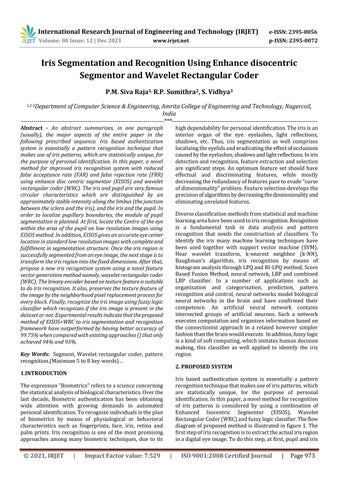
Iris based authentication system is essentially a pattern recognitiontechniquethatmakesuseofirispatterns,which are statistically unique, for the purpose of personal identification.Inthispaper,anovelmethodforrecognition of iris patterns is considered by using a combination of Enhanced Isocentric Segmentor (EISOS), Wavelet RectangularCoder(WRC)andfuzzylogicclassifier.Theflow diagramofproposedmethodisillustratedinfigure1.The firststepofirisrecognitionistoextracttheactualirisregion inadigitaleyeimage.Todothisstep,atfirst,pupilandiris
Iris Segmentation and Recognition Using Enhance disocentric Segmentor and Wavelet Rectangular Coder P.M. Siva Raja1, R.P. Sumithra2 , S. Vidhya3 1,2,3Department of Computer Science & Engineering, Amrita College of Engineering and Technology, Nagercoil, India ***
Key Words: Segment, Wavelet rectangularcoder, pattern recognition.(Minimum5to8keywords)…
1.INTRODUCTION Theexpression"Biometrics"referstoascienceconcerning thestatisticalanalysisofbiologicalcharacteristics.Overthe last decade, Biometric authentication has been obtaining wide attention with growing demands in automated personalidentification.Torecognizeindividualsistheplan of biometrics by means of physiological or behavioral characteristics such as fingerprints, face, iris, retina and palm prints. Iris recognition is one of the most promising approaches among many biometric techniques, due to its highdependabilityforpersonalidentification.Theirisisan interior organ of the eye. eyelashes, light reflections, shadows, etc. Thus, iris segmentation as well comprises localizingtheeyelidsanderadicatingtheeffectofocclusions causedbytheeyelashes,shadowsandlightreflections.Iniris detectionandrecognition,featureextractionandselection are significant steps. An optimum feature set should have effectual and discriminating features, while mostly decreasingtheredundancyoffeaturespacetoevade“curse ofdimensionality”problem.Featureselectiondevelopsthe precisionofalgorithmsbydecreasingthedimensionalityand eliminatingunrelatedfeatures. Diverseclassificationmethodsfromstatisticalandmachine learningareahavebeenusedtoirisrecognition.Recognition is a fundamental task in data analysis and pattern recognition that needs the construction of classifiers. To identify the iris many machine learning techniques have been used together with support vector machine (SVM), Hear wavelet transform, k nearest neighbor (k NN), Baughman’s algorithm, iris recognition by means of histogramanalysisthroughLPQandRI LPQmethod,Score BasedFusionMethod,neural network,LBPandcombined LBP classifier. In a number of applications such as organization and categorization, prediction, pattern recognitionandcontrol,neuralnetworksmodelbiological neural networks in the brain and have confirmed their competence. An artificial neural network contains intersected groups of artificial neurons. Such a network executescomputationandorganizesinformationbasedon the connectionist approach in a related however simpler fashionthanthebrainwouldexecute. Inaddition,fuzzylogic isakindofsoftcomputing,whichimitateshumandecision making, this classifier as well applied to identify the iris region.
2. PROPOSED SYSTEM

Thefirststepofirisrecognitionistoextracttheactualiris regioninadigitaleyeimage.Todothisstep,atfirst,pupil and iris regions are segmented using enhanced isocentric segmentation (EISOS) method. The second step is to generatetheIriscodefeaturevectorandthentoconvertthe circular to rectangular using Wavelet Rectangular Coder (WRC).Inthefinalstep,theirisrecognitionisdonethrough fuzzyclassifier.
To control the access to limited places, modern security sciences use these differences which are one of the basic problems in security field. The rising necessitate of the securityfieldhasgivengouptothedevelopmentofcurrent and competent authentication systems. In several applicationareasoldapproachesofrecognitionsuchaskey orpasswordarenotsuitable.Theseconventionaltechniques canbeforgotten,stolen,orcracked.Fortheseweaknesses, the current science is concerned in automatic systems of recognitionwhicharebasedonbiometricstechnology.Into two major classes biometric identification is subdivided; physiological features such as fingerprints, iris and performance features such as voice. The necessitate of dependableandsecuresystemshasengagedtheemergence of the biometric system. Finger print, face and speaker recognition have been broadly studied. For authenticity check,amongallthebiometricrecognitionsystem(IRS)is themostcompetentanddependablesystem.FlamandAram suggested Iris recognition. Current surveys of iris recognitionalgorithmcanbefound.
Iris based authentication system is essentially a pattern recognitiontechniquethatmakesuseofirispatterns,which are statistically unique, for the purpose of personal identification.Inthispaper,anovelmethodforrecognition of iris patterns is considered by using a combination of Enhanced Isocentric Segmentor (EISOS), Wavelet Rectangular Coder (WRC) and fuzzy logic classifier. The architecture diagram of proposed method is illustrated in figure4.1.
4.1 Segmentation
Fig 1: ArchitectureDiagram
The iris and pupil are very famous circular characteristics
International Research Journal of Engineering and Technology (IRJET) e ISSN: 2395 0056 Volume: 08 Issue: 12 | Dec 2021 www.irjet.net p ISSN: 2395 0072 © 2021, IRJET | Impact Factor value: 7.529 | ISO 9001:2008 Certified Journal | Page974 regions are segmented using enhanced isocentric segmentation (EISOS) method. The second step is to generatetheIriscodefeaturevectorandthentoconvertthe circular to rectangular using Wavelet Rectangular Coder (WRC).Inthefinalstep,theirisrecognitionisdonethrough fuzzyclassifier.
section.Detailsthroughinvolvedbelow.segmentationbounIsophotessmoothing,theMoreboundariesiris),alongwhicharedistinguishedbyanapproximatelysteadyintensitythelimbus(thejunctionbetweenthescleraandtheandtheirisandthepupil.Inordertolocalizepupillarythemoduleofpupilsegmentationisplanned.specifically,themoduleisresponsibleforperformingfollowingfourprocessingsteps,namely:(i)image(ii)binaryimagegeneration(binarization),(iii)curvatureestimationand(iv)pupilcenteranddarylocalization.AdetaileddescriptionofthepupilproceduresinvolvedineachstepisgivenFortheillustrationpurpose,Fig.2showssomemajorprocessingproceduresandtheobtainedresultstheirrespectivesampleirisimagerepresentations.ineachsteparecoveredintheremainderofthis
1) Stage1:ImageSmooting Considerthegrayscaleimage ,whichhavesomeofthe noises; so we reduced the noise using smoothing methodology.Smoothingisoftenusedtoreducenoisewith animageortoproducelesspixilatedimage.
4. ARCHITECTURAL DESIGN
3. PROBLEM DEFINITION AND DESCRIPTION
International Research Journal of Engineering and Technology (IRJET) e ISSN: 2395 0056 Volume: 08 Issue: 12 | Dec 2021 www.irjet.net p ISSN: 2395 0072 © 2021, IRJET | Impact Factor value: 7.529 | ISO 9001:2008 Certified Journal | Page975
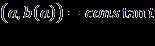
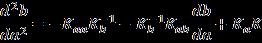
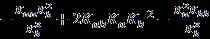
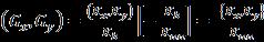
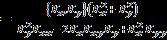
To divider data is the purpose of segmentation so as to appear at significant areas. The boundary among areas is calledanedge.Theaimofthisposteristodemonstratethe localizationerrorofcurvededgeswithoftenemployededge detection methods owing to the blurring effect. Now the blurring effect of the acquisition is modeled as the convolution with a point spread function (PSF). In our effort,thefirstandsecondderivativesintheXdirectionofan image K are indicated as, and correspondingly. The existingalgorithmisbasedonthestudyofthecurvatureof Isophotes, curves joining pixels in the image with equal intensity. The isophote curvature g is upright to the gradient and it is autonomous of the size of the gradient Isophotes properties make them mainly appropriate for objectsdetectionandimagesegmentation.Inspecific,ithas beenexpressedthattheirshapesareindependentofrotation anddifferinglightingconditions,and,incommon,isophote features result in improved detection performance than intensities,gradientsorHaar likefeatures. TobetterillustratetheIsophotesframework,thenotionof intrinsicgeometryisintroduced,i.e. geometrywithalocally definedcoordinatesystem.Alocalcoordinateframeissetin everypointoftheimage,insuchawaythatitspotsinthe direction of the maximal change of the intensity, which communicatestothedirectionofthegradient.Thisreference frame isaswellreferredtoasthegaugecoordinates. Inafixedcoordinatesystemderivativesareworkedout.The vector b is termed in the direction of the gradient and ais uprighttob.Itsframevectors and aretermedas: (2) Where, and are the first order derivatives of the luminance function in x and y dimension, respectively.Inthissetting,aderivativeinthebdirectionis the gradient itself, and the derivative in the a direction (perpendicular to the gradient) is 0 (no intensity change alongtheIsophotes).Inthiscoordinatesystemtheisophote is defined as K and its curvature is definedasthechange ofthetangentvector .Byimplicit differentiationwithrespecttoaoftheIsophotesdefinition, weobtain: (3) (4) Since, from the gauge condition, then Thereforedifferentiating(3)onceagainrespecttoa,yields (4) By consider the equation (3) we substitute the and recalling that the isophote curvatureisobtainedas (5) Substitutingequation(3)into(4)yield, (6) = (7) = (8) The equation (8) in Cartesian coordinate it’s given in equation(9).
(1) Where; BinaryB Obtainedbinaryimage gray K Inputgrayscaleimage
2) Stage2:Binaryimagegeneration
3) Stage3:Isophotescurvatureestimation
Firstly,theirisimageisconvertedintobinaryimage,which meansitconvertsanimageofupto256graylevelstoablack andwhiteimage.Thegreylevelimportanceofeverypixelin the improved image is considered in this stage. The input imageisgivena thresholdvalueandcategorizesall pixels with values above this threshold as white, and all other pixels as black in image binarization process. The binarizationoperationherementionedaimsatidentifying andisolatingsomeregionsofinterestintherawinputimage from its background. The threshold value used for generating the desirable binary image is automatically estimatedinadvancefromthegraylevel histogramofthe improvedimage.


(13) Where arethedisplacementvectorstotheestimated position of the centers which can be mapped into an accumulator, hereinafter “center map”. The set of vectors pointingtotheestimatedcentersareshowninFigure3(b).
Fig 4:Thedirectionofthegradientundertheimage’s edges.
Fig -6:Thecentermap.
5) Stage5:Centrevotingandeyecenterlocation Reflect on the figure 3(a), we employing only three Isophotes;oneexplainingthepupil,oneexplainingtheiris
International Research Journal of Engineering and Technology (IRJET) e ISSN: 2395 0056 Volume: 08 Issue: 12 | Dec 2021 www.irjet.net p ISSN: 2395 0072 © 2021, IRJET | Impact Factor value: 7.529 | ISO 9001:2008 Certified Journal | Page976 (9)
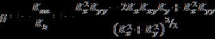
4) Stage4:Centerpositionestimationusingdisplacement Aftervectortheisophotecurvatureestimationusingsectionstage 3,wecalculatethecentreoftheisophoteinthissection.For everypixel,weareinterestedinretrievingthecenterofthe circlewhichfitsthelocalcurvatureoftheisophote.Wemake out the curvature is the reciprocal of the radius R; so equation (5) is turned around to attain the radius of this circleR. (10) The obtained radius magnitude is meaningless if it is not combined with orientation and direction. The orientation can be estimated from the gradient, but its direction will alwayspointtowardsthehighestchangeintheluminanceas shown in figure 4. However, the sign of the isophote curvaturedependsontheintensityoftheoutersideofthe curve (for a brighter outer side the sign is positive). Accordingly,bymultiplyingthegradientwiththecontraryof the isophote curvature, the sign of the isophote curvature assistsindisambiguatingthedirectiontothecenter.Asthe unitgradientcanbewrittenas ,wecontain(11)
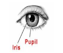
Where, and arethefirstandsecond orderderivativesoftheluminancefunction inthex andydimensionsrespectively.Tobetterrepresentationof the eye image, a simplistic eye model is used, shown in Figure2,theisophotecurvatureoftheeyemodelisshownin figure3. Fig 2:Theoriginaleyeandnotificationofpupilandiris. Fig 3:Isotopescurvatureattheedges.
Fig 5:Thedisplacementvectorspointingtotheisophotes centers.
When compared to Figure 4 it is possible to note that the vectorsarenowallcorrectlydirectedtowardsthecenterof the circular structures. Figure 5.2 (c) represents the cumulativevoteofthevectorsfortheircenterestimate(i.e. theaccumulator).Sinceeveryvectorgivesaroughestimate ofthecenter,theaccumulatorisconvolvedwithaGaussian kernelsothateachclusterofvoteswillformasinglecenter estimate. The contribution of each vector is weighted accordingtoarelevancemechanism.


The intermediate steps of the MIC determination are presented in table 1 to better understanding the concept clearly. Table 1: TheintermediatestepsoftheMICdetermination Steps Image1 Image2 Input Obtained centre Themapedges outputSegmentedvotecontributedthattotheoftheMIC
4.2 Feature extraction
Once pupil and iris regions are segmented using EISOS method,thefeatureextractionisperformedusingWavelet Rectangular Coder (WRC) algorithm. At first, Daugman’s Rubber Sheet Model is used to convert circular to rectangularconversion(CTRC)operation.Here,theirisarea i.e. polar coordinate is converted Cartesian coordinates. Therefore,irisarea isobtained asa normalizedstrip with regard to iris boundaries and pupillary center. The homogenous rubber sheet model is an efficient normalizationmethod,whichisdevisedbyDaugman(1993) usedfornormalizationprocess.Therectangularirisimage with size of M×N is then applied for the code generation processusingWRC(WaveletRectangularCoder)method.In order to design this, n level of wavelet decomposition is donebasedontheinputimageandthedesignedrectangular operator and iris code is generated based on nth level wavelet co efficient. The detailed process of the feature extractionschemeispresentedinthissubsection:
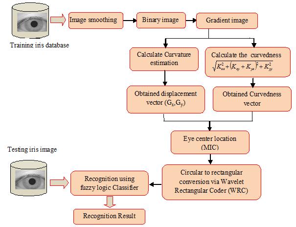
1) Daugman’sRubberSheetModel: Normalizationprocessincludesun wrappingtheiris andtransformingitintoitspolarequivalent.Itisperformed utilizingDaugman’sRubbersheetmodelandisdepictedin thefollowingfigure7,onpolaraxes,foreachpixelintheiris, itsequivalentpositionisfoundout.Theprocessconsistsof two resolutions: (i) Radial resolution and (ii) Angular resolution.Theformeristhenumberofdatapointsinthe radial direction whereas, the later part is the number of radial lines produced around iris region. Utilizing the following equation, the iris region is transformed to a 2D array by making use of horizontal dimensions of angular resolutionandverticaldimensionofradialresolution.
International Research Journal of Engineering and Technology (IRJET) e ISSN: 2395 0056 Volume: 08 Issue: 12 | Dec 2021 www.irjet.net p ISSN: 2395 0072 © 2021, IRJET | Impact Factor value: 7.529 | ISO 9001:2008 Certified Journal | Page977 and final one explaining the boundary of the sclera. By convolving the eye model with Gaussian kernel, it can be examined that the number of isophotes raises around the edgesasthesteepnessoftheedgereduces,andthateachof thesenovelisophotesissametotheoriginalisophotesthus weemploytoproduceadditionalevidencetovoteforright centre.The aroundvoteshenceareandthereedges.surfacesofgradientrequired.poiofcoulddiminisheddiscretizationprobleminadigitalimagecouldbeandinvariantandpreciseeyecentreestimationbeattainedbygatheringandaveraginglocalevidencecurvature.Tothisconclusion,animageoperatorthatntsouthowmucharegiondivergesfromflatnessisThisoperatoristhecurvedness,termedas(12)Thecurvednessisregardedasarotationalinvariantoperator,whichcalculatesthedegreeofsteepnessthegradient.Asaresult,itgivesuplowresponseonflatandedges,whileityieldshighresponsearoundtheAsisophotesareslicesoftheintensitylandscape,isastraightrelationamongthevalueofthecurvednessthedensityofisophotes.Asaresult,denserisophotespossibletobelongtothesimilarfeature(i.e.edge)andlocallyagreeonthesimilarcenter.Bysummingthebymeansofequation(5),weattainhighresponsesthecenterofisocentricIsophotespatterns.Wename these high responses “isocenters”, or ICs. The maximum isocenter (MIC) in the centermap will be employed as the mostpossibleestimateforthesoughtafterpositionofthe centeroftheeye. TheMICiscalculatedbaseduponthefollowingcondition:(13) Where, Displacementvectoratxdirection Displacementvectoratydirection
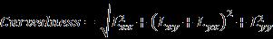
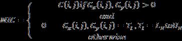


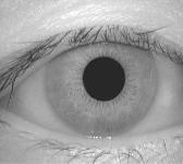
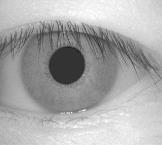
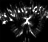
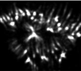
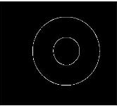
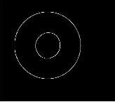
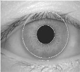
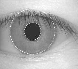
Fig 7: Daugman’sRubberShettModel. (16) Where, is the iris region, and are the Cartesian and normalized polar coordinates respectively. The range of is and ris and are described as linear combinations set of pupil boundary points. To perform the transformation, the formulas are givenintheprecedingequations (14) Where, and arethecoordinatesonthepupil and iris boundaries along the direction. are the coordinates of pupil and iris centers. This model gives a rectangular array with size of M×Nimagetogeneratebinarycodetoformfeatureset.
International Research Journal of Engineering and Technology (IRJET) e ISSN: 2395 0056 Volume: 08 Issue: 12 | Dec 2021 www.irjet.net p ISSN: 2395 0072 © 2021, IRJET | Impact Factor value: 7.529 | ISO 9001:2008 Certified Journal | Page978
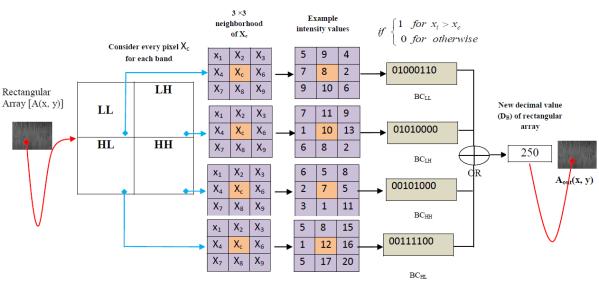
2) WaveletRectangularCoder(WRC) OnceCTRCoperationisdoneviaDaugman’sRubber SheetModel,thecodegenerationprocessisperformedusing Wavelet Rectangular Coder (WRC) algorithm. To effectiveness of the feature extraction stage, a novel algorithmisproposedcalledasWaveletRectangularCoder (WRC)toremoveorprocessthatcorruptedirispartsbased on the quality assumption. At first, wavelet transform is appliedtothenormalizedirisimage.Generally,waveletscan be used to analyze the data in the iris region in multi resolution mode. Wavelets have the advantage over traditional Fourier transform as the frequency data is localized in wavelet, allowing features which occur at the samepositionandresolutiontobematchedup.Thestepby stepprocessofWRCalgorithmisgivenbelow; Let the original image (rectangular array) be denoted as , the LL band transformation image be denoted as , HL band transformation image be denoted as , the LH band transformation image be denoted as the HH band transformation image be denoted as Thebinarycodeof denotedas , thebinarycodeof isdenotedas , thebinarycodeof isdenotedas and binarycodeof isdenotedas Theobtainedsingle8 bitbinarycodeisdenotedas and thecorrespondingdecimalvalueisdenotedas .Thefinal output of the rectangular array image is represented as b)Atfirst,theDWTisappliedanddecomposedintoFourier subbandslikeLL,HL,LH,andHH.Subsequently,eachsub bands are divided into set of blocks. Here, a set is representedas3*3blockswithcentrepixel c)Themainintentionistocodegenerationfromtheseeach 3*3blockstoreplacecenterpixelintheoriginalimage.Todo thisprocess,oneconditionisappliedoneachcentreblock basedoneachneighborhoodtogenerate8 bitbinarycode. Theconditionisgivenasfollows: (15) Where, thi Pixel Centerblockofthe3*3block ᶿ r Segmented eye image Normalized eye image r ᶿ


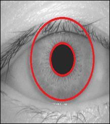

Fig 8: ExampleprocessoftheWavletRectangularCoder (3RC). 4.3 Recognition We have applied a fuzzy logic system using subtractiveclusteringfortherecognitionsamples.Thestep bystepprocessisexplainedbelow: 1) MembershipFunction In this model, the subtractive clustering is used to design membership function in input and output data points. In addition, the fuzzy rules are generated using subtractive clustering. Here, rule should have two different decisions like as YES and NO. From the rule set, sample rules are presentedintable2:
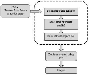
Therecognitionofirissampleiscarriedoutusingthefuzzy systemdesignedintheprevioussub section.Thetestingiris image isgiventothefuzzylogicsystem,wherethetestiris image is converted to the fuzzified value based on the fuzzy membership function. Then, the fuzzified input is matchedwiththefuzzyrulesdefinedintherulebase.Here, theruleinferenceprocedureisusedtoobtainthelinguistic value that is then converted to the fuzzy score using the average weightedmethod.Fromthefuzzy scoreobtained, thedecisionisgeneratedwhetherthetestirisimagebelongs totherecognitionornot. Thefigure9illustratestheFlow diagramofGenfis2based FuzzyInterferenceSystem. InterferenceSystem Fig- 9:FlowDiagramofGenfis2basedFuzzyInterference System
d) After this condition, 8 bit binary code is generated for each 3*3 blocks in every sub bands. Mathematically, the binarycodegenerationcanberepresentedas v e) After the binary code conversion, the OR operation is performedtoobtainsingle8 bitbinarycode f)Finally,thesingle8 bitbinarycode isconvertedtoequal decimalvalueandconsiderasthevalueofthecentralpixel value. The above process is repeated for whole image to g)obtainFinally, column wise mean value is taken for obtained M×Nimage,anditisdeductedtosizeof1×Nanditgivesto recognition phase. The figure 8 illustrates the numerical exampleoftheWRCprocess.
International Research Journal of Engineering and Technology (IRJET) e ISSN: 2395 0056 Volume: 08 Issue: 12 | Dec 2021 www.irjet.net p ISSN: 2395 0072 © 2021, IRJET | Impact Factor value: 7.529 | ISO 9001:2008 Certified Journal | Page979 thi block
Table -2: Sampleruleofthesystem Rules SampleRules copy Moretablecopya R1 IF (X1isC1)and(X2isC1) and(X3 isC2) and(X4isC1)and....(XNisC2)THENY0 =1 R2 IF(X1isC2)OR(X2isC1)OR(X3isC1)OR (X4isC2)OR....(XNisC1)THENY0=0. .. .. Rk IF(X1isC1)OR(X2isC2)OR(X3isC2)OR (X4isC1)OR....(XNisC2)THENY0=0 Where;R1,R2...Rkarethefuzzyrules,X1,X2,X3 XNare theinputattributeoftherectangulararraywithsize1×N. C1andC2aretheclusters.Y0is1meansrecognizedandY0 is0meansnotrecognized.


2) Error Message Iftheloginpasswordisincorrectitwilldisplayerror message InSegmentation,iftheselectedfileisnotapythonfile theerrormessagewillbedisplayedinthescreen.
5. TEST DATA AND RESULTS In this section we discuss the result obtained from the propose technique. For implementing the propose techniquewehaveusedpythonThisproposedtechniqueis done in windows machine having Intel Core i5 processor with speed 1.6 GHz and 4 GB RAM. For comparing the performance,weusingthreetypeofdatasetsuchasCASIA, UBRISandMMUirisimagedatabase.
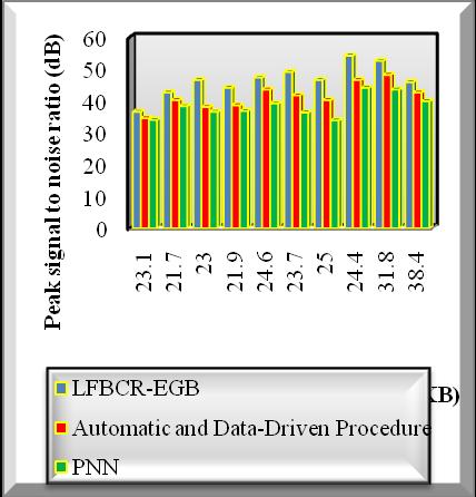
Table 3: PeakSignaltoNoiseRatioversusImageSize ImageBrain size (KB) Peaksignaltonoiseratio(dB) EGBLFBCR ProcedureDrivenandAutomaticData PNN 23.1 36.53 34.50 33.97 21.7 42.55 40.17 38.30 23.0 46.54 38.02 36.53 21.9 44.04 38.58 36.76 24.6 47.30 43.52 39.18 23.7 49.04 41.68 36.30 25.0 46.54 40.17 33.81 24.4 54.15 46.54 44.04 31.8 52.56 48.13 43.52 38.4 45.85 42.55 39.83
1)Accuracy: The Accuracy of the proposed method is the ratioofthetotalnumberofTPandTNtothetotalnumberof Where,data.FPstandsforfalsepositive, TPstandsfortruepositive, TNstandsfortruenegative, FNstandsforfalsenegative FalseAcceptanceRate(FAR):FARistheprobability rateatwhichnumbersofIrisimagesareerroneously receivedas“non match.
3) Performance Results of peak Signals to Noise Ratio
International Research Journal of Engineering and Technology (IRJET) e ISSN: 2395 0056 Volume: 08 Issue: 12 | Dec 2021 www.irjet.net p ISSN: 2395 0072 © 2021, IRJET | Impact Factor value: 7.529 | ISO 9001:2008 Certified Journal | Page980
In Feature extraction, if the selected file is not a pythonfile,itdisplays Anerrormessage Intherecognition,eitherthestartingpositionorthe ending position is not given, it will display error message.
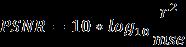
PeakSignaltoNoiseRatio(PSNR)iscomputedbasedonthe mean square error which is defined as the difference between noisy image and preprocessed image. The mean squareerrorandpeaksignaltonoiseratioiscomputedas follows, (16)(17)
The above table value clearly shows that the simulation resultsofpeaksignaltonoiseratiowithrespecttodifferent imagesizes. ThevariousMRIimagesarecollectedfromthe database.Theperformanceofthepeaksignalnoiseratioof the proposed LFBCR EGB technique is significantly improved when compared to the existing Automatic and Data Driven Procedure [1] and PNN [2]. The simulation graphwithvariousresultsisshowninfigure10.
The evaluation of proposed iris recognition technique in bench mark iris image database are carried out using the followingmetricsassuggestedbybelowequations,
FalseRejectionRate(FRR):FRRistheprobabilityrate atwhichthenumbersofirisimagesareerroneously receivedasmatch.
5.1 Evaluation Metrics


[6] W. Boles and B. Boashash, “A Human Identification Technique Using Images of the Iris and Wavelet Transform”,IEEETrans.SignalProcessing,vol. 46,No. 4, pp. 1185 1188,Apr. 1998
[8] Alireza Osareh and Bita Shadgar, “A Computer Aided DiagnosisSystemforBreastCancer”,IJCSIInternational JournalofComputerScienceIssues,Vol. 8,No.2, 2011.
Fig 10: SimulationResultsofPeakSignalstoNoiseRatio
[4] Samir Shah and Arun Ross, “Iris Segmentation Using Geodesic Active Contours”, IEEE transactions on informationforensicsandsecurity,vol. 4,No. 4, 2009
[5] J. Daugman, “High Confidence Visual Recognition of Persons by a Test of Statistical Independence”, IEEE Trans. Pattern Analysis and Machine Intelligence, vol. 15,No. 11,pp. 1148 1161,Nov. 1993
Figure10illustratesthesimulationresultsofthepeaksignal tonoiseratiobasedonthevariousimagesizefrom23.1KB 38.4KB.Theimagesizeistakenasinputin‘x’directionand thecorrespondingresultsofthepeak signal tonoiseratio are attained in ‘y’ direction. The above simulation result clearly shows that the proposed LFBCR EGB technique increasestheperformanceresultsofPSNRwhencompared toexistingmethods. Thisisbecause,proposedLFBCR EGB techniqueremovesthenoisesinanMRIimagethroughthe preprocessing steps. The LFBCR EGB technique uses the weightedleefilter. ThisPSNRiscomputedbyestimatingthe mean square error between the original size and quality enhancedimage.Theoriginalimageshaveafewnoisypixels to minimize the image quality for lesion localization. The weightedleefiltermonitorsthepixelintheimagesandits adjacentpixels.Theentirepixelsinanimagearearrangedin ascendingorderandfindthecenterpixelsandmodifiedthe allthepixelsalongwiththecenterpixels.Thecenterpixels inawindowremovethenoisypixels.Asaresult,thepeak signaltonoiseratiogetsimproved.
Theobjectiveofthisresearchwastodemonstrateirisimage segmentationandrecognition.Here wehaveintroduceda new method namely, iris segmentation recognition using EISOS+ WRC approach. Here, first the iris image was segmentedusingtheenhancedisocentricsegmentor(EISOS) method.Afterthesegmentationweconvertthesegmented imageintotherectangularcoordinatesusingtheDaugman’s Rubber Sheet Model. Once we convert the rectangular coordinates,thecodegenerationprocessisperformedusing Wavelet Rectangular Coder (WRC) algorithm. Finally, the fuzzylogicclassifierisusedtorecognizetheirisimageusing the fuzzy rules. The iris recognition performance is measuredusingdifferentdatasetsuchas,CASIA,MMUand UBIRIS dataset. Experimental results indicate that the proposed methodofEISOS+WRCtoirissegmentationand recognitionframeworkhaveoutperformedbyhavingbetter accuracy of 99.75.9% when compared with existing approachonlyachieved94%and93%.
International Research Journal of Engineering and Technology (IRJET) e ISSN: 2395 0056 Volume: 08 Issue: 12 | Dec 2021 www.irjet.net p ISSN: 2395 0072 © 2021, IRJET | Impact Factor value: 7.529 | ISO 9001:2008 Certified Journal | Page981
[1] J.Wayman,A.Jain,D.Maltoni,andD.Maio,“Biometric Systems”,Springer, 2005
6. CONCLUSION
[3] C. Tisse, L. Martin, L. Torres, and M. Robert, “Person IdentificationTechniqueUsingHumanIrisRecognition”, Proc. 15th Int’l Conf. Vision Interface, pp. 294 299, 2002.
[9] Karabatak, M., Ince, M.C., “An expert system for detectionofbreastcancerbasedon associationrules andneuralnetwork”,ExpertSystemswithApplications, Vol.36,pp.3465 3469, 2009
REFERENCES
[7] J. Daugman, “New methods in iris recognition”, IEEE Trans. Syst. Man Cybern Part B Cybern., vol.37, pp. 1167 1175, 2007
[2] L. Ma, T. Tan, Y. Wang, and D. Zhang, “Efficient Iris Recognition by Characterizing Key Local Variations”, IEEE Trans. Image Processing, vol.13, No. 6, pp.739 750,June 2004
BIOGRAPHIES Dr. P.M. Siva Raja presentresearch interests include Machine Learning in medical image processing and information securityinimageprocessing.Heis currently working as Assistant Professor at Amrita College of Engineering and Technology, Amritagiri,KanyakumariDistrict.

International Research Journal of Engineering and Technology (IRJET) e ISSN: 2395 0056 Volume: 08 Issue: 12 | Dec 2021 www.irjet.net p ISSN: 2395 0072 © 2021, IRJET | Impact Factor value: 7.529 | ISO 9001:2008 Certified Journal | Page982
Mrs. R.P. Sumithra pursuing her research in Computer aided medical image using Deep Learning techniques. She is currently working as Assistant Professor at Amrita College of Engineering and Technology, Amritagiri,KanyakumariDistrict
Mrs. S. Vidhya received her M.E degree from the Department of CSE, Anna University, Chennai in 2012, her B.E degree from the Department of CSE, Anna University,Chennaiin2010.Heis currently working as Assistant Professor at Amrita College of Engineering and Technology, Amritagiri,KanyakumariDistrict.