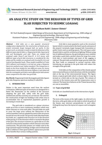
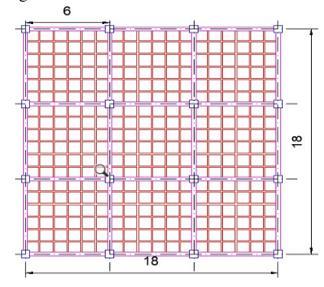
Fig 1: Orthogrid
STUDY ON THE BEHAVIOR OF TYPES OF GRID SLAB SUBJECTED TO SEISMIC LOADING Shubham Rathi1, Sameer Chitnis2
1M. Tech Student[Computer Aided Design of Structure], Department of Civil Engineering , SDM college of Engineering and technology, Dharward, India 2Assistant Professor , Department of Civil Engineering , SDM college of Engineering and technology, Dharward, India ***
Key Words: Diagonalgridslab,Rectangulargridslab,Square gridslab,Responsespectrummethod,E tabs2016 1. INTRODUCTION Shelter is the most important need from the earliest civilizations.Differenttypesofstructuresaredesignedfora better life. Researches on the comfort of the structure adopting the grid slab, safety with the grid slabs, aestheticismandtheeconomyarecarriedout.Theneedfor theconstructionofhigh risebuildingintheurbanarea to accommodate due to exponential population growth is increasinginrecentdays The grid slab is considered as a planar structure made up of two or more continuous members which may eitherintersectorcrosseachother.Thegridslabsareused to cover the large areas without the obstruction of the verticalmembersandareadoptedbymostofthestructures locatedallovertheworld.Thegravityloads(likedeadloads, liveloads,etc..)appliedtothestructureareinthedirection ofthegravityorinthedirectionwhichisnormaltotheplane ofthegrid.Thestructureisknownasagrid slabasitisthe inclusionofhorizontalmemberswhichintersecteachother continuously.Thegridslabsystemsarewidelyusedinthe largespannedsupportbuildings,bridgesandoverheadtank gridsinadditiontotheirgoodaestheticappearanceprovide morebenefitsthanvariousroofingsystems.
Gridslab ismost popularly usedasthestructural layoutwhichisconstructedinthehotel'sporch,entrancesof theairports’terminals,larger banquethall,Convention or publicCentreandcarparkingspaces.Thevoidspaceunder thegridslabisusedforarchitecturallighting.Withoutusing lotsofadditionalfeatures,thegridslabgivesmorestability andmakesagrid slabaperfectchoiceforlargefreeareas. Grid slab is crack resistant and most of the sagging is reduced.Thegrid slabcanholdthelargergravityloadslike the floor loads as compared to normal concrete slabs. Introducing an opening in the grid slabs will reduce the strengthofthegridslab. Gridslabsarethecompositionofthecloselyspaced interconnectedbeamsinbothdirectionswiththemonolithic slab at the top of the interconnected beams. The figure showsa typical grid slabwhichisshownfig(1).It may be termed as a thick slab on the top of grids. The volume of concrete in the tension zone and the compression zone is reduced.ThebeamherebehavesastheTbeambecausethey arecastasmonolithic.
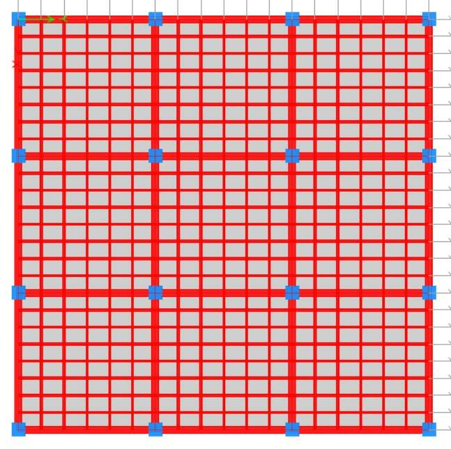
1.1 Types of grid Slab Gridslabareclassifiedbasedontheintersectionofgrids 1. Orthogrid Thetermorthomeansattherightangles.Asreferredtoin theterm,orthogrid slabsaretheslabsinwhichthegridsof the beams may intersect perpendicular to each other. Orthogridsmayhavethelayoutofasquareandrectangular grid.
International Research Journal of Engineering and Technology (IRJET) e ISSN: 2395 0056 Volume: 08 Issue: 12 | Dec 2021 www.irjet.net p ISSN: 2395 0072 © 2021, IRJET | Impact Factor value: 7.529 | ISO 9001:2008 Certified Journal | Page947 AN ANALYTIC
Abstract - Grid slabs are a very popular structural configuration deployed for the construction of hotels porch, airport terminals, larger banquet hall, car parks. In this project work, an attempt is made to study the behaviourof the different types of grid slabs i.e. Diagonal grid slab, Squaregrid slab and Rectangular grid slab. These are studied and analyzed under Zone II and Zone IV. A G+9 storey with different types of grid slab structures is considered for this study and the models are analyzed with Gravity(DL+LL) and Lateral (earthquake) loads. These models modelled in E tabs 2016 software and analysis is carried out using a Response Spectrum method as per Indian standard. The comparison is made on the three models for two different zones, for storey displacement, storey drift and storey stiffness, it was observed that the rectangular grid slab ismoreeffectiveforbothseismic zones compared to the other two grid slab

3 Methodology
3 Mostoftheindustrialbuildingsadapttothegrid slabs asthemetalandthetimbergridsareusedinmostofthe temporarystructures 4 Grid slabsareusedinthespaceswherethestructures needmorestability 5 Usedforspecialstructures.
9.
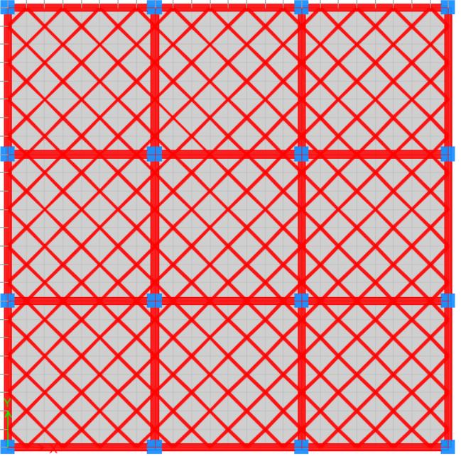
1. Model 1:Diagonalgridslab
4.
1.3
1. Theyhaveusedaflatsurface. Nobeamexcavationisrequired. Theyareabovetheground. CardboardSlabpanelareused. Trenchmeshorindividualbarscanhaveused. The spacing of beams is usually 0.75mm to 1.5m sometimesevenupto2mspacingshouldbeprovided. TheDepthofthebeamkeptaround1/25thto1/20thof thegrid slabspanbasedontheintensity. The Width of the grid slab beam should not be lesser than1/3rdto1/4thofdepth. The width of the panel should be at least 1/4th the depth of the rib or 65mm, whichever has the greater value. Thedepthoftheslabofthegridslabcanhaveaslightly lesserdepth. Theminimumdepthofgrid slabrequiredisequaltothe sumoftwotimesofthecoverplusthediameterofthe bar.
1. To analyses and study the structural behavior of various kinds of grid slabs considered for the structuresubjectedtoseismicloading.
5.
6. Comparative study on following parameters in considerationwithbothzones: 7. Storey displacement, Storey drift and Storey stiffness
11.
8.
1.2 Features of Grid Slab
12. Thereisminimumconcretevolume.
6.
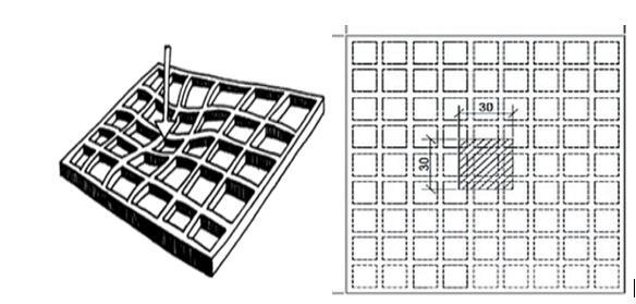
The beams in the diagonal grid slabs are cut across the diagonals for architectural perspective. The figure below showsthediagonalgrid slabs.
10.
Fig 2: Diagonalgrid
2 AgridSlabisusedasthesubstitutefortheobstruction freespacethatisneeded.
1. A study of literature on RCC framed multi storey residentialstructureofG+9ofstorey.
5. Analysis of prepared model and understand the structural behaviour of model in both zones separately.
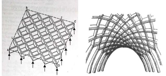
International Research Journal of Engineering and Technology (IRJET) e ISSN: 2395 0056 Volume: 08 Issue: 12 | Dec 2021 www.irjet.net p ISSN: 2395 0072 © 2021, IRJET | Impact Factor value: 7.529 | ISO 9001:2008 Certified Journal | Page948 2. Diagonalgrid
2. Preparation of frames layout on considering particularbuildingdimensionsandcolumnspacing.
3.1. Modelling ThecommercialRCstructuresaremodelledbyusingE tabs software. The current project deals with the G+9 multi storiedRCFrameStructurelocatedinzoneIIandzoneIVas perIndianStandardcodesisconsideredfortheanalysis.The designed frames structures are studied for Gravity and seismic loads for the response spectrum method. The structureiscompared for maximum Storey Displacement, maximumStoreyDriftandmaximumStoreyStiffness.The below shownmodelswereconsideredfortheanalysis
3. ModellingthepreparedlayoutintoETABSsoftware on assigning material specification and gravity loads.
3.
4. Assigning the lateral seismic loads under seismic ZoneII&IVseparately.
13. Theyused30%lessconcreteand20%lesssteelbythe stiffenedraft. Advantages of Grid Slab Gridslabcanbeusedasbothcellingandfloorslab. 1 Grid slabcanbeusedasbothceilingwithouttheuseof additionalceilingworksforaestheticperfections.
7.
2.
2. OBJECTIVES Thefollowingaretheobjectiveofthepresentstudy
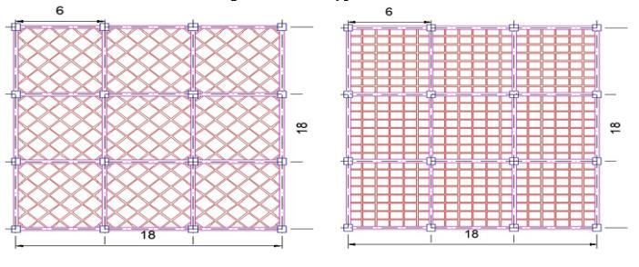
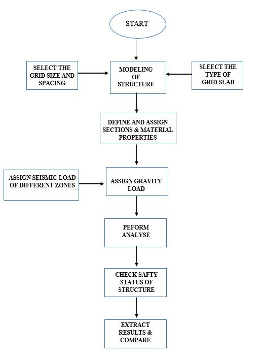
International Research Journal of Engineering and Technology (IRJET) e ISSN: 2395 0056 Volume: 08 Issue: 12 | Dec 2021 www.irjet.net p ISSN: 2395 0072 © 2021, IRJET | Impact Factor value: 7.529 | ISO 9001:2008 Certified Journal | Page949 2. Model 2;Rectangulargridslab 3. Model 3:SquaregridSlab Model 1 Model 2 Model 3 Fig-3: DifferentTypesofGridSlab 3.2. Methodology Theactivityofanalysisanddesignofstructureperformance onCSIE TabsinaccordancewithIS456:2000,IS1893:2002, IS875:1987(Part1,Part2,Part3)isshownthroughtheflow chart. Fig-4: Flowchart 3.3 Description of TableStructure1:MaterialProperties Sl,No MATERIALSPECIFICATION 1 GradeofConcrete,M 30 Fck=30N/mm2 2 GradeofSteel,Fe 500 Fy=500N/mm2 3 Densityofconcrete Ƴ=25KN/m3 Table 2: Structuraldetailandsectionalproperties oN,Sl NSSPECIFICATIO DIFFERENTTYPESOFGRIDSLAB SLABALDIAGONGRID SLABARRECTANGULGRID SLABGRIDSQUARE 1 Plan 18mX18 18mX18m 18mX18
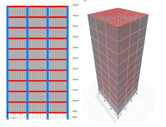
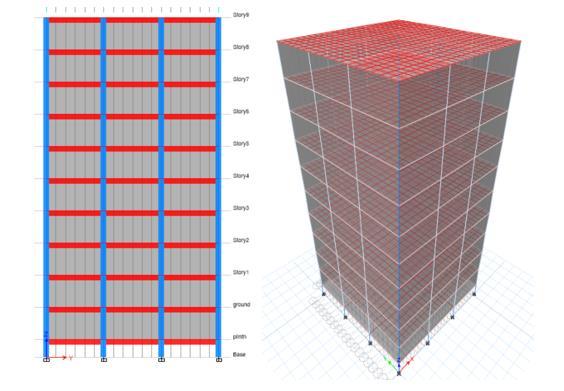
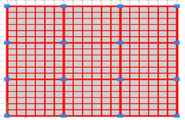
International Research Journal of Engineering and Technology (IRJET) e ISSN: 2395 0056 Volume: 08 Issue: 12 | Dec 2021 www.irjet.net p ISSN: 2395 0072 © 2021, IRJET | Impact Factor value: 7.529 | ISO 9001:2008 Certified Journal | Page950 Dimension m m 2 LengthofGrid inX direction 6m 6m 6m 3 LengthofGrid inY direction 6m 6m 6m 4 Floor to Floor height 3.5m 3.5m 3.5m 5 No.ofStories 9 9 9 6 PlinthLevel 2m 2m 2m 7 SlabThickness 150mm 150mm 150mm 8 SizeofBeam 300 600mmX 300 X 600mm 300 600mmX 9 SizeofColumn 600 X 600mm 600 X 600mm 600 600mmX 01 SizeofGrid 100 300mmX 100 X 300mm 100 300mmX 11 inSpacingofGridXdirection 75mm 75mm 100mm 21 inSpacingofGridYdirection 75mm 75mm 75mm 31 Grade of concrete M30 M30 M30 41 GradeofSteel Fe 500 Fe 500 Fe 500 Table 3: GravityLoadCondition GRAVITYLOADS DeadLoad DefaultvaluestakenbyE tabs LiveLoad 3kN/m2 FloorFinish 1kN/m2 WallLoad 12kN/m2(.23X2.9X18) Table 4: SeismicLoadCondition LATERALLOADS(SeismicLoad) EarthquakeZone II IV ZoneFactor,Z 0.1 0.24 Response Reduction Factor,R 3 3 ImportanceFactor,I 1.5 1.5 SoilType Type (Medium2Soil) Type (Medium2Soil) Table-5: WindLoadCondition Windloads WindSpeed,Vb 33m/s TerrainCategory 3 StructureClass B Riskco effcient,k1 1 Topography,k3 1 3.4. E-Tabs Models Fig 5: Plan,Elevationand3DviewofDiagonalGridSlab Fig 6: Plan,Elevationand3DviewofRectangularGrid Slab
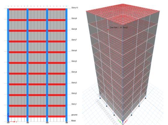
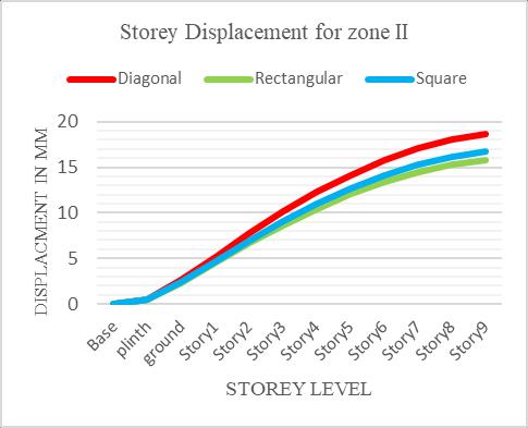
International Research Journal of Engineering and Technology (IRJET) e ISSN: 2395 0056 Volume: 08 Issue: 12 | Dec 2021 www.irjet.net p ISSN: 2395 0072 © 2021, IRJET | Impact Factor value: 7.529 | ISO 9001:2008 Certified Journal | Page951 Fig 7: Plan,Elevationand3DviewofSquareGridSlab 4. Results and discussions 4.1 Storey Displacement for Earthquake Zone II The comparison between Storey displacement of Seismic loading of Diagonal grid slab, Rectangular grid slab and square grid slab for seismic zone II as shown in table 6 below. Story Diagonal Rectangular Square Base 0 0 0 plinth 0.462 0.4238159 0.429 ground 2.59 2.3202273 2.378 Story1 5.177 4.5204768 4.7 Story2 7.743 6.6667913 6.987 Story3 10.126 8.6578954 9.111 Story4 12.271 10.456912 11.028 Story5 14.157 12.043046 12.715 Story6 15.765 13.395237 14.15 Story7 17.067 14.486107 15.307 Story8 18.031 15.286386 16.156 Story9 18.665 15.794648 16.701 Table 6: StoreyDisplacement(mm) Fig 8: StoreyDisplacementbyResponseSpectrum
International Research Journal of Engineering and Technology (IRJET) e ISSN: 2395 0056 Volume: 08 Issue: 12 | Dec 2021 www.irjet.net p ISSN: 2395 0072 © 2021, IRJET | Impact Factor value: 7.529 | ISO 9001:2008 Certified Journal | Page952
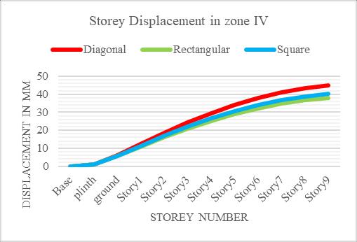
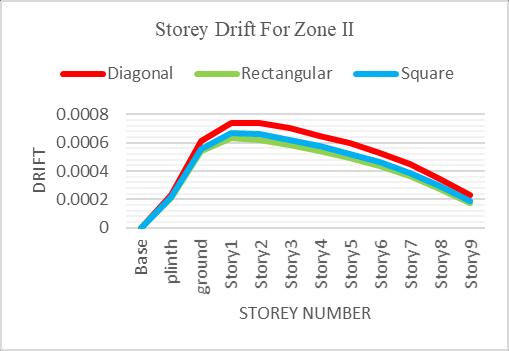
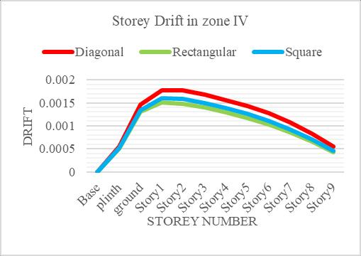
34.767 36.737 Story8 43.276 36.687 38.774 Story9 44.795 37.907 40.081 Table 7: StoreyDisplacement(mm) Figure 9: ForSeismicZoneIV,thegraphisplottedfor StoreynumberinX direction&displacementinY direction.Thegraphexpressthatthestoreydisplacement ofthediagonalslabis1.1%to1.2%greaterthanthe squareandrectangulargridslab. 4.3. Storey Drift for Earthquake Zone II: ThecomparisonbetweenStoreydriftofearthquakeloading ofDiagonalgridslab,Rectangulargridslabandsquaregrid slabforseismiczoneIIasshownintable8below. Story Diagonal Rectangular Square Base 0 0 0 plinth 0.000231 0.000212 0.000214 ground 0.000608 0.000542 0.000557 Story1 0.000741 0.00063 0.000665 Story2 0.00074 0.000619 0.000659 Story3 0.0007 0.000582 0.000622 Story4 0.000649 0.000538 0.000575 Story5 0.000594 0.000489 0.000523 Story6 0.000529 0.000432 0.000462 Story7 0.000448 0.000361 0.000387 Story8 0.000345 0.000273 0.000294 Story9 0.00023 0.000174 0.000191 Table 8: StoreyDrift Fig-10: StoreyDriftbyResponseSpectrum Figure 10: For Seismic Zone II, the graph is plotted for StoreynumberinX direction&storeydriftinY direction. Thegraphexpressthatthestoreydriftofthediagonalslabis 1.2%to1.3%greaterthanthesquareandrectangulargrid slab. 4.4. Storey Drift for Earthquake Zone IV: ThecomparisonbetweenStoreydriftofearthquakeloading ofDiagonalgridslab,Rectangulargridslabandsquaregrid slabforseismiczoneIVasshownintable9below. Story Diagonal Rectangular Square Base 0 0 0 plinth 0.000555 0.000509 0.000514 ground 0.001459 0.0013 0.001337 Story1 0.001778 0.001511 0.001595 Story2 0.001777 0.001484 0.001582 Story3 0.00168 0.001397 0.001492 Story4 0.001558 0.001292 0.00138 Story5 0.001425 0.001174 0.001255 Story6 0.001271 0.001036 0.001109
Figure 8: ForSeismicZoneII,thegraphisplottedforStorey number in X direction & displacement in Y The graphexpressthatthestoreydisplacementofthediagonal slabis1.1% 1.2% thanthesquareandrectangular gridslab.
1.017 1.029 ground
5.569 5.707 Story1 12.426 10.849 11.28 Story2 18.583 16 16.769 Story3 24.301 20.779 21.867 Story4 29.45 25.097 26.468 Story5 33.977 28.903 30.516 Story6 37.837 32.149 33.961 Story7
below. Story
greater
direction.
to
4.2. Storey Displacement for Earthquake Zone IV: The comparison between Storey displacement of Seismic loading of Diagonal grid slab, Rectangular grid slab and square grid slab for seismic zone IV as shown in table 7 Diagonal Rectangular Square Base 0 0 0 plinth 1.109 6.216 40.961
193663.77
express
drift
The comparison between
191957.031 Story5
International Research Journal of Engineering and Technology (IRJET) e ISSN: 2395 0056 Volume: 08 Issue: 12 | Dec 2021 www.irjet.net p ISSN: 2395 0072 © 2021, IRJET | Impact Factor value: 7.529 | ISO 9001:2008 Certified Journal | Page953 Story7 0.001075 0.000866 0.000928 Story8 0.000828 0.000654 0.000705 Story9 0.000553 0.000419 0.000458 Table 9: StoreyDrift
Figure 11: For Seismic Zone II, the graph plotted for StoreynumberinX direction&storeydrift Y graph thatthestorey ofthediagonalslabis thesquareandrectangulargrid Storey Stiffness Earthquake Zone IV: Storey grid 159696.37 240658.09 Story4 158363.98 238271.16 158581.35 159403.7 159787.58 234023.91 157038.5 228246.97 128457.77
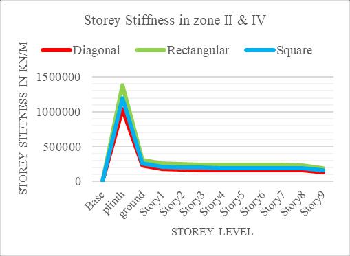
slab, Rectangular grid slab and squaregridslabforseismiczoneIIandIVasshownintable 10below. Story Diagonal Rectangular Square Base 0 0 0 plinth 1038735.1 1380643.1 1192846.52 ground 224931.95 309385.11 261538.969 Story1 175865.29 256475.98 209661.913 Story2 163637.87 244845.35 197616.904 Story3
189835.97 154110.105
direction. The
slab. 4.5.
II and
1.2%to1.3%greaterthan
in
235831.33 191518.961 Story7
Figure 12: ForSeismicZoneII&IV,thegraphisplottedfor Storey number in X direction & storey Stiffness in Y direction.ThegraphexpressthatthestoreyStiffnessofthe Rectangularslabis1.2%to1.3%greaterthanthesquareand diagonalgridslab.
236910.97 191511.173 Story6
for
5 CONCLUSIONS ThebehaviourofG+9multi Storeybuildingwithdifferent typesofgridslab(Square,RectangularandDiagonal)with twodifferentseismiczonesisstudiedbycomparingvarious parameters such as Storey displacement, Storey drift and Storeystiffness. Basedontheaboveresultsobtaineditcanbeconcludedthat therectangulargridslabismoreeffectiveforbothseismic zonescomparedtosquareanddiagonalgridslab.Thestorey displacementandstoreydriftfoundinrectangulargridslab iscomparativelylowerthanthatofsquareanddiagonalgrid slabforseismiczoneIIandzoneIVbecausetherelationship between storey displacement and storey stiffness is inverselyproportionaltoeachother.Hencethestiffnessof the rectangular grid slab is higher than the Square and Diagonalgridslab. Thediagonalgridslabshowsmorestoreydisplacementand storeydriftcomparedtothatofrectangularandsquaregrid slab.Hencethestiffnessofthediagonalgridslabisless.So the diagonal grid slab sways more compared to the other twogridslabsandthedamagecausedbytheearthquaketo thediagonalgridslabstructurewillbehigher. The result also reflects that the studied properties of the squaregridslablieinbetweentherectangularanddiagonal grid Henceslab.RectangularandSquaregridslabshouldbepreferred overtheDiagonalgridslab.
Fig 12: StoreyStiffnessbyResponseSpectrum
is
Fig 11: StoreyDriftbyResponseSpectrum
191012.46 Story8
Stiffness of earthquake loading of Diagonal
187052.112 Story9
Table 10: StoreyStiffness
[1] HarishMK,“AnalysisandDesignofGridSlabinBuilding
Check the stability of the grid slab for composite structure.
[3] Ayush Rai and Vikash Kumar Singh, “Comparison of BeamShearAnalysisbetweenFlatSlabandGridSlabof High Rise Buildings with Varying Geometry under Seismic and Wind Loading Condition”., International Journal of Innovative Research in Technology and Management,Vol 4,Issue 4,2020
[8] 8.SSBhavikatti.”Design(RCCVolume II)AdvanceRCC “NewageinternationalPublisher [9] 9. IS456:2000, Plain and Reinforced concrete Code practices.
[2] Dr Ramakrishna Hegde, Chethana, Nanditha Vinod Kumar, “Comparative Study On Seismic Analysis of ConventionalSlab,FlatSlabandGridSlabSystemforA R.C Framed Structures”, International Journal for ResearchTrendsandInnovation(2018IJRTI).
[4] Mr.TejasBI,Mr.RaghuME,“AStudyontheBehaviorof Grid Slab Subjected to Seismic Loading” International Journal for Research Trends and Innovation (2018 IJRTI).
The analysis and design of grid slab structure with regularandirregularshapebuildings.
REFERENCES
[7] 7. Mrs. N. Monica Madhuri, “Analysis and Design of Multistorey Building With Grid Slab Using E Tabs.”,InternationalJournalofResearch.
The earthquake resisting structure can be used for analysistoincreasetheeffectivenessofthestructure.
Checkthestabilityofthegridslabstructureforwind analysisfordifferentshapeofgridslab.
[11] 11. IS1893:2002, Criteria for earthquake resistance designofstructure.
International Research Journal of Engineering and Technology (IRJET) e ISSN: 2395 0056 Volume: 08 Issue: 12 | Dec 2021 www.irjet.net p ISSN: 2395 0072 © 2021, IRJET | Impact Factor value: 7.529 | ISO 9001:2008 Certified Journal | Page954 Scope for Future Work
[6] AnjaliMishraandAnuragBajpai,“ComparativeAnalysis of Waffle Slab of Different Configuration & Deflection Check by Manual Method & Software Based Method” Journal of Civil Engineering and Environmental Technology,Volume7,Issue2;2020
[5] Anithu Dev, Jasmin S.P., Shinu Shajee, “Analysis and ParametricStudyofWaffleSlabs”.,InternationalJournal forResearchTrendsandInnovation(2017IJRTI).
[10] 10.IS875:1987 Part I,Part II,Part III,Codeapproach for design loads, Part I;Dead Load, Part II;Live Load, Part III;WindLoad.
Theanalysisanddesignofgridslabstructurescanbe donebyusinglinearstaticanalysis,non linearstatic analysisandnon lineardynamicanalysis.
Using Response Spectrum Method”, International Journal for Research Trends and Innovation (2017 IJRTI).