Pratap M1 , Suhas U2 , Manjunath T.V. 3 , Dr.Suneelkumar.N.Kulkarni4 1Student, Dept. of Mechanical Engineering, Cambridge Institute of Technology, Karnataka, India
2Asst.Professor, Dept. of Mechanical Engineering, Cambridge Institute of Technology, Karnataka, India
Abstract Airline operational costs are increasing constantly for structural component repair due to debris impact. The resulting damage is estimated to cost the aerospace industry $4 billion a year. Foreign objects at airport can be anything that positioned inappropriately and cause damage to the aircraft structural components, Aircraft personal and other equipment. Foreign objectscanincludeanymateriali.e. Inhabitantanimals,birds, repair tools, loose hardware, bolts, nuts, and other parts falling from previous aircraft. Even though the major accidental scenarios like bird strike, Hail stone impact, and lightning strike are considered in Aircraft certification procedure; debris impact damage level on aircraft structural component and its fatigue life requirements are not reported specifically in certification Sodocuments.debrisimpact study is an essential part in defining fatigue and threshold life limits of an aerospace components. This helps in defining aerospace certification requirements and avoids major accidental damage.
Thereviewsummarizesthepreviouseffortonthe‘Damage toleranceassessmentoffuselageandrunwaydebrisimpact study. There were many researches being carried out on fatiguecrackgrowthbehaviorofdifferentstructures,impact analysis and lofted runway debris. Here are few papers referredbelow: J.O. Peters, R.O. Ritchie [1], examined Influence of foreign object damage on crack initiation and early crack growth during high cycle fatigue of Ti 6Al 4V alloy. The particleimpactonmetallicsubstancessubjectedtoforeign object damage. The objective of this paper is to provide a rationaleapproachtodefinethelimitingconditionsforhigh cyclefatigue(HCF)inthepresenceofforeign objectdamage (FOD).ThisstudyfocusedontheroleofsimulatedFODin affecting the initiation and early growth of small surface fatigue cracks in a Ti±6Al±4V alloy, processed for typical turbine blade applications. Using high velocity (200±300 m/s) impacts of 3.2 mm diameter steel spheres on the surfaceoffatiguetestspecimenstosimulateFOD,itisfound thattheresistancetoHCFismarkedlyreducedduetoearlier crackinitiation.Prematurecrackinitiationandsubsequent near threshold crack growth is primarily affected by the stress concentration associated with the FOD indentation andthepresenceofsmallmicro cracksinthedamagedzone (seenonlyatthehigherimpactvelocities).
2. Literature Review
***
SeyedMasoudMarandi [2], explains the foreign object damageontheleadingedgeofcompressorblades.Foreign object damage (FOD) usually happens when objects are sucked into jet engines powering military or civil aircraft. Underextremeconditions,FODcanleadtoseverestructural damage.Morecommonlyitproduceslocallyimpactedsites of the fan and compressor airfoils, reducing fatigue life of thesecomponents.FODisaprimecauseforrepairinaircraft
3Asst.Professor, Dept. of Mechanical Engineering, Cambridge Institute of Technology, Karnataka, India
Duringtheaircraftlifecycletime,commercialandmilitary aircraft parts are subjected to foreign objects like rivet mandrels,partsofgroundvehicles,maintenance,stones,hail andbirdcollisionsetc..,otherthananypartoftheaircraftis known as foreign object to that aircraft. The resulting damageiscalledforeignobjectdamage(FOD).Damageby hardparticlesmainlyoccurs,duringtake offandlandingor during motion of the aircraft on the airfield. Aircrafts on runway are mainly subjected to these foreign objects and damagetheaircraft'sengine,wingfuselageandnosalregion. Worldwide the FOD costs the aviation sector US$14 billion per year in direct plus indirect costs. Every airline operatorsarefacingmilliondollarslossduetomaintenance of the plane from FOD's. The crash of aircrafts such as Concorde(July,2000)andBombardierLearjet36A(March, 2007)wasduetothepresenceofrunwaydebris.As90%of FOD's are Bird strike, the other 10% include sand storm, hail stone, runway debris like lofted stones, nuts, bolts, aircraftpartsfrompreviousairplaneonrunway,etc.
International Research Journal of Engineering and Technology (IRJET) e ISSN: 2395 0056 Volume: 08 Issue: 12 | Dec 2021 www.irjet.net p ISSN: 2395 0072 © 2021, IRJET | Impact Factor value: 7.529 | ISO 9001:2008 Certified Journal | Page936
4Professor, Dept. of Mechanical Engineering, Cambridge Institute of Technology, Karnataka, India
Debris Impact Study Fuselage Panel
1. INTRODUCTION
Thesmallloftedstonesfromtireshavemajorimpacton airplanefuselagewhichcreatesvisibledamage,howeverin somecasesonlyminorscratchesordentswithmeasurable crackmaydevelop,whichmaybeleftundetectable.However someloftingstonedeflectionsystemsareavailable,itmakes theundercarriagedesignmorecomplexandit'sdifficultto maintaininlargeraircrafts.Sothebehavioraircraftfuselage paneltosuchastoneimpactatvariousvelocitiesandangles is studied and fatigue life is predicted for the component understoneimpactatdifferentthermalconditions.
Key Words: Debris, Foreign Object Damage (FOD), Low Cycle Fatigue, Stone Impact, Threshold

Perform a comprehensive study between pristine anddamagemodeltoknowthedebrisimpactlevels duetodebris
Fatigue
S.N. Nguyen, E.S. Greenhalgh, R. Olsson, L. Iannucci, P.T. Curtis [3], detailstheparametricAnalysisofRunway StoneLoftingMechanisms.Theinfluenceofvariousfactors affectingtheseverityofrunwaydebrisloftingmechanisms wasinvestigatedbyperformingnumericalsimulationsand dropweightimpactexperimentstoassessthelikelihoodofa stone impact. Geometrical characterisation of stones collected from airfields led to a generic model of a tyre rollingoverstonesofvariousshapewithdifferentoverlaps, orientations,anddensities.Innumericalsimulationsofa0.4 mdiameteraircrafttyrerollingat70m/s,a10mmdiameter sphericalstonewasloftedatamaximumverticalspeedof35 m/s.Forequivalentmassprolatespheroidstones,theloft speeds were 11 to 34% lower depending on the stone orientation. Objects with flat surfaces exhibited different lofting mechanisms and lower angular velocities. The conditionsmostconducivetostoneloftingwereverystiff, smalldiameter,sharpcorneredtyresrollingongroundwith ahighfrictioncoefficientoversphericalstonessuchthatjust underhalfthestonediameterwascoveredbythetyre.The stone loft speed was approximately proportional to the square root of the tyre tread stiffness. Finally, tyre tread grooves could throw stones upwards at the tyre ground separation speed, which was 17 m/s for the conditions mentioned.
International Research Journal of Engineering and Technology (IRJET) e ISSN: 2395 0056 Volume: 08 Issue: 12 | Dec 2021 www.irjet.net p ISSN: 2395 0072 © 2021, IRJET | Impact Factor value: 7.529 | ISO 9001:2008 Certified Journal | Page937 engines.Inthisstudy,theimpactontheedgeofathinplate isexaminedbyusingthefiniteelementmethod.Thesecond step in the analysis focuses on the comparison between quasi staticindentationandfullydynamicimpactforthree criticallocationswhereresidualhoopstressesaretensile.
3. Methodology Analysisofproblemstatement Literaturesurvey Identifythefuselagepanelgeometryandmaterial aspercurrentdesign GeometrycreationusingCADsoftwareCATIA FiniteElementmodelingandloadapplicationusing preprocessingtoolHypermeshorPATRAN FEModelsolutionusing solvertoolNASTRAN Fuselage panel safe life cycle calculation using damagetolerancetoolNASGRO. Comparetheallowablecyclebetweenpristineand damaged(Stoneimpact)fuselagepanels. Objective Ifappliedstresslevelonthefuselagepaneldueto stone impact is capable of initiating the crack; estimatethelifecycleofthecomponentwithDTA techniquesusingNASGROtool.
Tensile
Properties
Summary: The literature review clearly stated the significance of impact analysis for the metallic materials. Besides the description of the past work, the survey evidenced the finite element method as the pertinent methodtoaccommodatetheanalysisofsuchstudies.
5.2 Material Selection HavingbetterfatiguestrengthmostAircraftmanufactures use Al 2000 series sheet metal in making fuselage panels forthecommonusagematerialAl2219 T62sheet aregiven UltimatebelowTensile 414Mpa YieldStrength 290Mpa Young'sModulus 73.1Gpa ShearStrength 255Mpa Strength 103Mpa Poisson'sRatio 0.33
The finite element model considered for this analysis is shownbelow
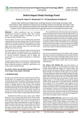
Fig 1: FuselagePanelConsideredForAnalysis
4.
5.2 Finite Element Model Creation
Strength
5. Analysis Procedure 5.1 Geometry AircraftFuselagepanelconsideredforanalysisisshownin below figure. Considering the complexity of the structure part of the fuselage is considered in analysis with ModelappropriateboundaryconditionsimulationinFiniteElement
Table-1: FuselagePanelMaterialProperties
Determine the threshold limit based on crack propagationlevel

1 1.5 2
From the above mentioned literature the debris stone mass10Kg and acceleration 11.2 m/s2 considered conservativelyinthisstudy. FromtheNewton’ssecondlaw, Forceappliedonthestructureisdirectlyproportionaltoits accelerationi.e.,F=mxa Wheremisthemassofthehittingbody(Kg) aistheaccelerationofthebody(m/s2) SotheimpactforceisF=10x11.2=111.2N=25lbs 5.4 FEM Pre and Post Processing: Stone impact location, Boundary condition, Panel deformation due to applied load and its stress results are showninfollowingfigures: Fig 3: LoadapplicationandBoundaryCondition
StressMisesvon Mesh Density vonMises Stress Linear (vonMises Stress)
To define the appropriate mesh density in Finite Element Modelatradestudywasperformedwithdifferentmeshsize by applying a constant magnitude load. Based on results (meshdensityVsvonMises)comparison,meshconvergence is observed to be at 0.5in. Hence mesh density with 0.5in consideredinanalysis. 0.5
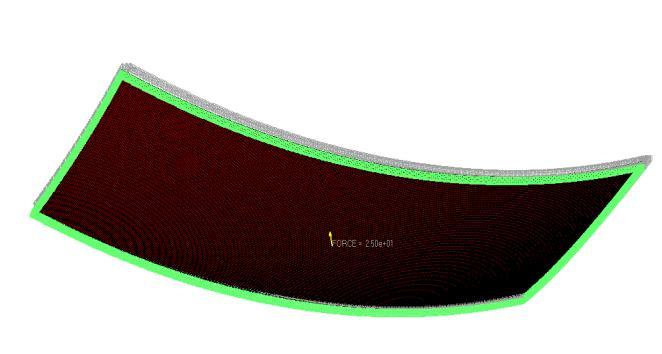
Fig-5: Appliedthermalloadforhotdayscenario FuselagepanelvonMises plot fortheappledload isshown below
International Research Journal of Engineering and Technology (IRJET) e ISSN: 2395 0056 Volume: 08 Issue: 12 | Dec 2021 www.irjet.net p ISSN: 2395 0072 © 2021, IRJET | Impact Factor value: 7.529 | ISO 9001:2008 Certified Journal | Page938
Fig 2: AircraftFuselagePanelFiniteElementModel
THERMALPLOT FORHOTCASE500˚F
Chart-1: MeshdensityVsvonMisesstress 5.3 Impact Load Calculation
Fig 4: PanelDeformationduetoappliedload Analysisperformedatdifferentenvironmentalthermalload conditions(ISAday:163F,Coldday: 65FandHotday:500F) and critical thermal load plot mapped on FEM is shown below Temperatureappliedontheofthepanel
0.00 2.00 4.00 6.00 8.00 10.00 12.00 14.00 0


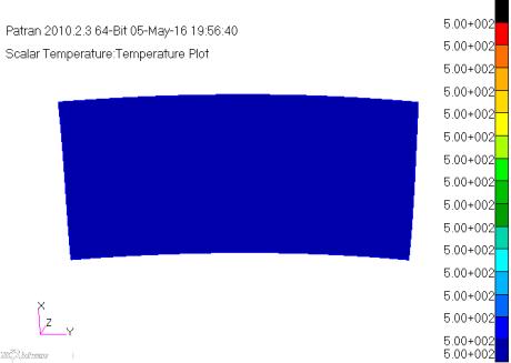
Considering the stress level from above graph, a crack growthanalysisisperformedusingNASGRO tool,safelife andthresholdnumberofcyclesaredetermined Crackscan begroupedinthreedifferentlengthclassifications;flawsize, inspectable size, and critical size. These criteria are illustratedinbelowFigureonthecrackgrowthcurve.
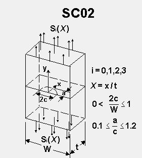
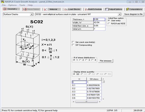
Considering the crack growth study is for sheet surface; chooseSC02inNASGROtool.
OuputsummaryfromtheNASGROtoolisshownbelow:
Resulted critical crack size is 0.9in and obtained safe life cyclesbeforecrackpropagationis1.86E+7cycles.Threshold lifecalculationdetailsaregivenbelow.
Fig 10: NASGROoutputsummary
Fig 8: CrackgrowthmodelinNASGROtool
Fig 7: Crackgrowthcurve
Fig 9: Crackgrowthmodelinputdatabase
International Research Journal of Engineering and Technology (IRJET) e ISSN: 2395 0056 Volume: 08 Issue: 12 | Dec 2021 www.irjet.net p ISSN: 2395 0072 © 2021, IRJET | Impact Factor value: 7.529 | ISO 9001:2008 Certified Journal | Page939
Chart 2 No.ofcyclesVscracksize
Fig 6: vonMisesstressplotfordebrisimpact
2134 EconomicLife KKK F F crit thr Where Fthr=Flightstothresholdinspection
Fromtheabovestresscontourplotstressgradientalongthe normalizeddistancearecalculatedandprovidedasinputto theNASGROtool.Alsorequiredgeometryandmaterialdata informationisprovidedintool.
CrackgrowthstudyperformedconsideringA tipandC tip crackapproachandresultsareshownbelow:


1.20E+08
Fcrit=Numberofflightsfrominitialflawsizetocritical cracklengthK1=Scatterfactorforsourceofcrackgrowth
FollowingthesimilaranalysisapproachusingNASGROtool pristinepanellifecyclesarecalculatedandobservedtobe infinite. Allowedcycleforfuselage panelconsideringDebrisImpact Allowedcyclefor pristinepanel withoutImpactDebriscycleAllowable Crack Length (inches) 1.86E+07 0.057 InfiniteLife 9.75E+07 0.111 1.07E+08 0.123 0.136 0.143 1.36E+08 0.485 1.38E+08 0.684 1.40E+08 0.901 Chart-3 PristineVsDebrisimpactmodellifecycle
REFERENCES [1] J.O. Peters, R.O. Ritchie 'Infuence of foreign object damage on crack initiation andearly crack growth duringhigh cyclefatigueofTi±6Al±4V'Departmentof MaterialsScienceandMineralEngineering,Universityof California,USA. [2] SeyedMasoudMarandiandKhosrowRahmani,'Foreign Object Damage on the Leading edge of compressor blades'fromWaterUniversityofTechnology,USA.
6. CONCLUSION Fromabovestudydebrisimpactfuselagepanellifecycles arelow/notinfinitecomparedtothepristinemodel.Sothe aircraft certification requirements should include an additionaldesignrequirementtomeetdesignlifecriteriafor small debris impact. Also this study can be extended to multi axial loading with flight loads for more detailed understanding of the damage caused by even the tiniest debriswithgreaterimpactforce.
1.15E+08
International Research Journal of Engineering and Technology (IRJET) e ISSN: 2395 0056 Volume: 08 Issue: 12 | Dec 2021 www.irjet.net p ISSN: 2395 0072 © 2021, IRJET | Impact Factor value: 7.529 | ISO 9001:2008 Certified Journal | Page940
[3] S.N.Nguyen,E.S.Greenhalgh,J.M.R.Graham,A.Francis, R.Olsson[5],'MethodologyforPredictingtheThreatof Runway Debris Impact to Large Transport Aircraft', '53rd AIAA/ASME/ASCE/AHS/ASC Structures, Structural Dynamics and Materials Conference, Honolulu, 23 26, (April 2012) Paper no: AIAA 2012 1377.
K3=Scatterfactorforenvironmentaleffects
K4=Scatterfactortoaccountforuncertaintiesinthe SanalysistoneimpactloadsareonlyconsideredinthisFEMstudy;a safetyfactorof5andEnvironmentalfactorof4considered in threshold calculation conservatively. LifeofthecomponentN=1.86E+7/(4x5) =930,000cycles
data