Basedontheinvestigations,inthisstudy microstrippatch antenna is designed with Bakelite, benzocyclobutane, RT Duroid 5880, and Taconic as substrate and Copper, aluminum, brass, and bronze are used as conducting material. This work has been carried out to analyze the Basedontheinvestigations,inthisstudymicrostrippatch antenna is designed with Bakelite, benzocyclobutane, RT
Theantennacanbedesignedusingthedifferentsubstrates, whichgivesdifferentresultswiththesameshapeandsize. Somesubstrategivesmoregainbutfailsinsomecaseslike cost,size,frequencyrange,efficiency,etc.orsomemaygive thebestefficiencybutitcanbeexpensive.Someconducting materials give the best performance and some may not. Depending on the properties of materialsselectedand the design,theantennaperformancewillchange.Henceinthis project, an attempt to investigate how the antenna performancechangeswithrespecttomaterialsanddesign hasbeeninvestigated.Furtherwithdifferentsubstratesand designs,performancehasbeenstudied.Donotaddanykind ofpaginationanywhereinthepaper.
3. LITERATURE REVIEW
Manyresearchershaveworkedonthedesignmaterialsof antennastoevaluatetheantennaperformance.Substrates suchasleather,silk,andnylonareusedforsmartclothingin therangeof3.3 3.7GHz[1].Similarworkhasbeenproposed byconsideringdifferentdielectricsubstratessuchasfoam, benzocyclobutane, duroid, roger 4350, Duroid 6010, and EpoxyFR_4 toenhancetheefficiencyoftheantenna[2].A fork shaped microstrip antenna was designed using differentsubstrates,andthesatisfactoryvalueofVSWRand returnlosswasachievedforbakelitesubstrate[3]. Therectangularmicrostripantennahasbeendesignedand observed the performance of the antenna by varying the substrate heights [4], Patch thickness [5] and different conducting materials such as copper, aluminum, brass, stainless steel[6], graphin[7] and a thin film of yttrium barium copper oxide (YBCO) superconductor [8]. The performanceofanantennacanbeimprovedbyintroducing theslotsinthepatch[9]andalsobyusingthemetamaterial structures[10]. Fromtheliteraturesurvey,itisinvestigatedthattheFR4 Epoxygivesthebestperformanceanditischeap,soitisbest suitableforthe5Gsub 6GHzband (f<6GHz).Forthe 5G high frequencyband(f>24GHz)RTDuroid5880isthebest suitable substrate, which gives better performance. Increasingthesubstrateheightincreasesthebandwidthbut reduces the gain and directivity. An increase in the patch thickness helps to increase the gain and directivity. The conductingmaterialalsocausesadifferenceintheresults. Theconductingmaterialwithgoodconductivitygivesmore gain.Soinmostcases,copperisusedasconductingmaterial. Anotherwaytoimprovethegain,bandwidth,andmultiband istousethemetamaterialsandslotsinthepatch.
2. PROBLEM STATEMENT
International Research Journal of Engineering and Technology (IRJET) e ISSN: 2395 0056 Volume: 08 Issue: 12 | Dec 2021 www.irjet.net p ISSN: 2395 0072 © 2021, IRJET | Impact Factor value: 7.529 | ISO 9001:2008 Certified Journal | Page73 Investigation of Effect of Design Materials on the Performance of an Antenna Spoorti Vagga1, Suma M N2 1,2Department of Electronics and Communication, BMS College of Engineering Bangalore, India *** Abstract - In many applications that demand a high data rate, there is a need for efficient system design. In view of this different techniques and designs are proposed to increase multiband.inhavingdielectricobservedbysimulationthickness,substrates,antennahasdependsgivenperformanceapproachsystemefficiencytoprovidethisthroughputdemand.Onesuchistodesignanantennathatprovidesthebestintermsofdirectivity,bandwidth,gainforaapplication.Theperformanceoftheantennamainlyonthedesignmaterialsoftheantenna.Thisprojectbeencarriedouttoanalyzetheperformanceofanbysimulatingtheantennadesignswithdifferentconductingmaterials,patchandsubstratemetamaterialuseandslotsinthepatch.Theofanantennahasbeendoneat2.4GHZfrequencyusingtheHFSStool.Fromthesimulationresults,itcanbethattheantennawiththesubstratehavinglessconstantgivesbetterperformancebutthesubstratehighdielectricconstantoffersacompactantenna.Slotsthepatchhelptoimprovethegain,directivityand Key Words: Rectangularmicrostrippatchantenna,Antenna parameters,Designmaterials,Metamaterials,Slots 1. INTRODUCTION The antenna acts as a transformer between conducted waves and electromagnetic waves propagating freely in space. There are many types of antennas such as wire, aperture, reflectors, lens, microstrip and array antennas dependingonshape,size,andperformance.Theantennais selected based on the application and the antenna’s performance.Theperformanceofanantennaismeasuredin termsofantennaparameterssuchasfrequency,bandwidth, gain,directivity,VSWR,returnloss,insertionloss,efficiency, etc. Antenna parameters mainly depend on the design materialsusedforantennamanufacturing.Sotheselection ofdesignmaterialsisveryimportanttodesignaflexibleand efficientantenna.

Substrate
4. MICROSTRIP PATCH DESIGN EQUATIONS
5. METHODOLOGY: ANTENNA SIMULATION AND PERFORMANCE ANALYSIS Simulation of an antenna is done using the HFSS tool. Antennaparameterssuchasgain(G),directivity(D),return loss (S11), bandwidth (BW), and VSWR are observed to analyzetheantennaperformance.Simulationisperformed for different substrates, heights of the substrate, width of transmission line, patch thickness, conducting material, usingmetamaterialandintroducingslotsinthepatch Here antenna is designed for 2.4GHz operating frequency andthethicknessofthesubstrateis1.5mm.Themicrostrip feedlineisusedasafeedingtechniqueandinsetfeedingis usedtoperfectimpedancematching.Alumpedportisused to excite the antenna. Antenna design parameters for differentsubstratesareshowninTable 1.
Antennadimensions
Table
Simulationresultsofanantennawithdifferent substrates Substrate S11 G D BW VSWR RT 5880Duroid 26.38 7.15 7.42 130 0.83 obutaneBenzocycl 20.40 7.14 7.21 110 1.66 TLCTaconic 34.98 6.26 6.79 150 1.66 Bakelite 28.69 5.50 6.005 130 0.63 From Table 1 and 2, it can be observed that the substrate withalessdielectricconstantgivesalargepatchandresults in more gain and directivity. Taconic having dielectric constant3.2gives 34.98dBreturnloss,150MHzbandwidth, andagainof6.26.RTDuroidhavingdielectricconstant2.2 gives 26.38dBreturnloss,130MHzbandwidth,whichisless thantheTaconicbutgivesbettergainanddirectivity.From the literature survey and simulation results, it can be concluded that the substrate with less dielectric constant givesthebestperformance
2.2 41×49 60×60×1.5 10×5 14×1 obutaneBenzocycl 2.6 38×46 60×60×1.5 12×4.5 311.7× TLCTaconic 3.2 34×43 52×52×1.5 10×2.5 9.5×1 Bakelite 4.8 28×36 45×45×1.5 10×3.5 9.5×2 5.1
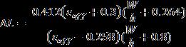
Thewidthofthepatchiscalculatedby Theeffectivedielectricconstantisgivenby Theeffectivelengthisgivenby Theextensionlengthisgivenby Theactuallengthofthepatchisgivenby Thelengthandwidthofthegroundplaneisgivenby Thelengthandwidthofthe substratearethesameasthe lengthandwidthofthegroundplane.
Table 1: fordifferentsubstrates Patch Ground Feed Inset RT 5880Duroid Effect of Substrate 2:
© 2021, IRJET | Impact Factor value: 7.529 | ISO 9001:2008 Certified Journal | Page74 Duroid 5880, and Taconic as substrate and Copper, aluminum, brass, and bronze are used as conducting material.Thisworkhasbeencarriedouttoanalyze.
International Research Journal of Engineering and Technology (IRJET) e ISSN: 2395 0056 Volume: 08 Issue: 12 | Dec 2021 www.irjet.net p ISSN: 2395 0072
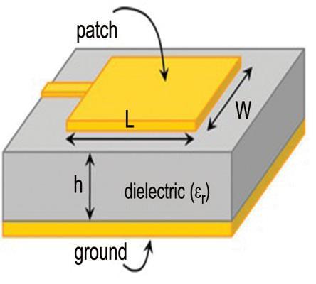
The basic structure of the rectangular microstrip patch antennaisshowninFig.1.Thedimensionsofarectangular microstrip antenna can be calculated by using the given formulae. The calculation needs three parameters such as operatingfrequency(f0),substrateheight(h)anddielectric constantofthesubstrate(Ɛr).
Fig 1: Basicstructureofrectangularmicrostrippatch antenna


5.2 Effect of Substrate Thickness(h) The antenna is designed by using the RT Duroid 5880 substratewithƐr=2.2andcopperasconductingmaterial Table 3: Simulationofanantennawithdifferentheights ofsubstrate h (inmm) S11 G D BW VSWR 1.1 8.55 6.99 7.43 70 6.815 1.3 15.44 7.11 7.44 80 2.96 1.5 26.38 7.15 7.42 130 0.83 By observing Table 3, the gain, directivity, and bandwidth increase with the increase in the height. From simulation resultsandliteraturesurvey,itcanbeconcludedthatasthe height of substrate increases, it results in less return loss, moregain,andbandwidth.Butthisheightshouldbealways less than 0.05 . Ifthe heightis beyond the limit, the patch stopsradiating.
Table 6: Simulationresultsofanantennawithdifferent substratesandconductingmaterials Substrate Conductingmaterial S11 G D BW DuroidRT5880 Copper 26.38 7.15 7.42 Aluminium 26.92 7.11 7.42 Brass 27.68 6.98 7.41 Bronze 27.32 6.9 7.42 Benzocyclobutane Copper 20.40 7.14 7.21 110 Aluminium 20.59 7.10 7.21 110 Brass 20.87 6.96 7.21 Copper Brass Bronze Copper Aluminium Brass Bronze 22.68 From the Table 6, it can be observed that the different conducting material gives different effect on the various substrates. Copper gives less return loss with Bakelite, Aluminium gives less return loss with Taconic and gives a bandwidthof170MHz.BrassgiveslessreturnlosswithRT duroid and benzocyclobutane. But copper gives more gain thanothers.Sofromsimulationresultsandliteraturesurvey, itcanbeconcludedthatthematerialwithgoodconductivity ismostpreferable.
5.3 Effect of Width of Transmission Line (Wt) Table 4: Simulationresultsofanantennawithdifferent widthsoftransmissionline Wtmm)(in S11 G D BW VSWR 3 7.55 7.14 7.41 60 7.80 4 10.73 7.15 7.40 100 5.19 5 26.38 7.15 7.42 130 0.83 6 5.38 6.99 7.37 10.44 From Table 4, Gain and directivity are increased with an increaseinthewidthofthetransmissionlineanditachieves more bandwidth withless return power. Beyonda certain point,botharedecreased,andreturnlossismore.Resonating frequency can be shifted by varying the width of the transmissionline. 5.4 Effect of Patch Thickness (Tp) Table 5: Simulationresultsofanantennawithdifferent patchthickness Tpmm)(in S11 G D BW VSWR 0.1 22.12 7.21 7.45 110 1.36 0.05 26.38 7.15 7.42 130 0.83 0.025 23.46 7.18 7.44 120 1.16 From Table 5, the gain and directivity increase with the increase in the patch thickness but there is a decrease in bandwidth.Fromtheliteraturesurveyandtable4.5,itcanbe observedthattogetthebestperformanceofanantenna,the patchthicknessshouldbeverymuchgreaterthantheskin depthvalueoftheconductingmaterial.
5.5 Effect of Conducting Material
28.69 5.50 6.005 130
5.6 Effect of Metamaterial (a) (b) Fig 2: Antennadesignwith(a)metamaterial1(b) metamaterial2
5.25 6.005 120
130
27.32 5.46 6.005 130
130
110 Bronze 20.81 6.88 7.21 110 TaconicTLC
39.44 6.11 6.78 150
27.32 6.04 6.78 140 Bakelite
130
34.98 6.26 6.79 150 Aluminium 49.50 6.20 6.77 170
24.12 5.33 6.005 130
130
International Research Journal of Engineering and Technology (IRJET) e ISSN: 2395 0056 Volume: 08 Issue: 12 | Dec 2021 www.irjet.net p ISSN: 2395 0072 © 2021, IRJET | Impact Factor value: 7.529 | ISO 9001:2008 Certified Journal | Page75


FromTable8,RTDuroidwithmetamaterialstructure2gives lessreturnlossandmorebandwidth.BycomparingtheTable
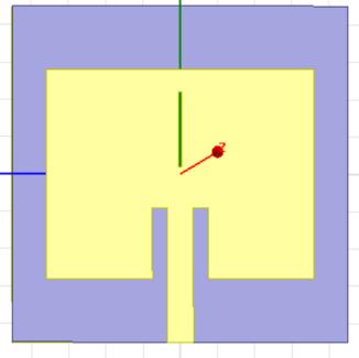
5.7 Effect (a) (b) Fig 3: Antennadesignwith(a)singleslot(b)
of Slots
1. Single Slot Etched in Patch: Table 9: Simulationresultsofanantennawithsingleslot inpatch Substrate S11 G D BW VSWR Bakelite 31.43 5.48 0.46 Benzocyclobutane 24.12 7.10 RT5880Duroid 26.35 7.17 7.42 130 0.83 TaconicTLC 45.90 6.26 6.80 170 0.08 From Table 9, it can be observed that the slot etched in a patchgivesbetterresults.Ascomparedtotable4.2,thegain anddirectivityareincreasedwiththisdesign.Byplacingthe slotsinthepatch,theantennawithTaconicsubstrategivesa littleamountofreturnlossandmorebandwidthbutincase ofgainanddirectivity,RTduroidgivesthebestperformance
5.99 150
2 and Table 8, the use of this metamaterial decreases the returnlossandincreasesthegain,directivityandbandwidth. From the literature survey and the simulation results, metamaterials will help to decrease the return loss and increasethegain,directivityandbandwidth.
International Research Journal of Engineering and Technology (IRJET) e ISSN: 2395 0056 Volume: 08 Issue: 12 | Dec 2021 www.irjet.net p ISSN: 2395 0072 © 2021, IRJET | Impact Factor value: 7.529 | ISO 9001:2008 Certified Journal | Page76
7.19 130 1.08
2. Metamaterial Structure2: Table 8: Simulationresultsofanantennawith metamaterialstructure2 Substrate S11 G D BW VSWR Bakelite 29.14 5.55 6.04 130 0.606 Benzocyclobutane 23.88 7.12 7.21 120 1.11 RT5880Duroid 36.85 7.11 7.38 150 0.24 TaconicTLC 36.27 6.32 6.83 150 0.26
twoslots
2. Two slots Etched in patch: Table 10: Simulationresultsofanantennawithtwoslots inpatch Substrate S11 G D BW VSWR Bakelite 19.06 5.47 6.03 110 1.94 Benzocyclobutane 25.51 7.08 7.20 130 0.92 RT5880Duroid 27.02 7.19 7.45 130 0.77 TaconicTLC 17.56 6.21 6.79 90 2.31 FromTable10,benzocyclobutaneandRTDuroidgivesmore gainanddirectivitywithlessreturnloss.Fromtheliterature survey and simulation results, it can be observed that the slotshelptoincreasethegain,directivity,andmultibandbut causeasmallincreaseinthereturnloss.Returnlosslessthan 20dB is most preferred. So the antenna design with RT Duroid5880substrateandcopperasaconductingmaterial gives better performance at 2.4GHz and some more frequencies 6. RESULTS AND DISCUSSIONS Simulationresultsofanantennaaremadebychangingthe antenna design materials such as patch designs, substrate thickness, patch thickness, transmission line width, conductingmaterials,andmetamaterials.Fromtheresults,it can be concluded that the antenna with low dielectric constant offers more gain, directivity, bandwidth, and less returnlossbutthesizeofthepatchislargerthantheantenna with the substrate having more dielectric constant. The substratewithhighthicknessprovidesthebestperformance and thickness should be less than 0.05 The next design parameter to be considered is the patch thickness, which must be greater than the skin depth value of conducting material
1. Metamaterial structure1: Table 7: Simulationresultsofanantennawith metamaterialstructure1 Substrate S11 G D BW VSWR Bakelite 31.43 5.48 5.99 150 0.46 Benzocyclobutane 24.12 7.10 7.19 130 1.08 RT5880Duroid 26.35 7.17 7.42 130 0.83 TaconicTLC 45.90 6.26 6.80 170 0.08
FromTable7,Taconicgivesthebestperformanceamongthe other substrates using the metamaterial. Using this metamaterial decreases the return loss and increase the bandwidth,gainanddirectivityofanantennawithRTDuroid andBakelitesubstrate but there isaslight decrease inthe gain and directivity of an antenna with Taconic and Benzocyclobutane.
[6] G. Kaur et al., "Performance analysis of conductive patch materials for the design and fabrication of microstrip patch antennas", 2017 Progress In Electromagnetics Research Symposium Spring (PIERS), 2017, pp. 502 508, doi: 10.1109/PIERS.2017.8261793.
[7] M.S.Khan,A.D.Capobianco,S.M.Asif,A.Iftikhar,B.D. Braaten,andR.M.Shubair,"Apropertiescomparison between copper and graphene based UWB MIMO planarantennas",2016IEEEInternationalSymposium on Antennas and Propagation (APSURSI), Fajardo, 2016,pp.1767 1768.
[5] Khan, Sahib & Ahmad, Nasir & Wahid, Muneeza & Naeem, Muhammad & Baloch, Bangul "Design of CircularStudAntennaandParametricAnalysis",Sindh University Research Journal SURJ (Science Series) 2015,47.231 235.
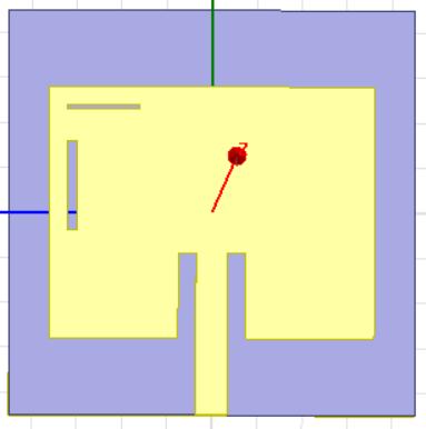
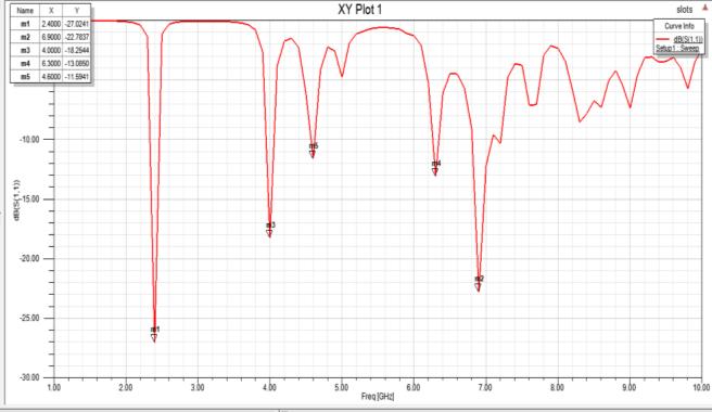
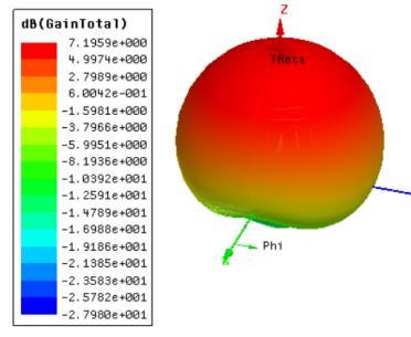
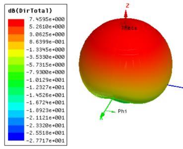
International Research Journal of Engineering and Technology (IRJET) e ISSN: 2395 0056 Volume: 08 Issue: 12 | Dec 2021 www.irjet.net p ISSN: 2395 0072 © 2021, IRJET | Impact Factor value: 7.529 | ISO 9001:2008 Certified Journal | Page77 Highconductivitymaterialiswellsuitedforantennadesign toachievelessreturnlosswithmoregain.Aluminumcanbe usedasconductingmaterialtoachieveverylessreturnloss andhighbandwidth.Gainanddirectivityoftheantennaare improvedbyintroducingtheslotsinthepatchandmultiband can also be achieved. Metamaterials are more suitable for improvingtheantennaperformance,mainlyinimprovingthe multibandandbandwidthenhancement Insimulatedantennas,theantennawithdoubleslotsinthe patchprovidesthebestperformance.ItusesRTDuroid5880 assubstrate,copperasconductingmaterial,andprovides 27.02dB return loss with 130MHz Bandwidth at 2.4GHz resonatingfrequency.Thegainofthisdesignis7.19dBand directivityis7.45dB.Theadvantageofthisdesignisthatit offers multiband at 4GHz, 4.6GHz, 6GHz, and 6.3GHz frequencies,asshowninFig.4.Thisantennacanbeusedin WLANapplications. (a) Returnloss (b) Gain (c) Directivity Fig 4:Simulationresultsofanantennawiththedouble slotsetchedinpatch 7. CONCLUSION AND FUTURE SCOPE From the results of investigation and simulation, it can be concluded that the antenna with copper as a conducting materialandsubstratehavinglessdielectricconstantismore patchbandwidthincreasescopewithAntennawithetchedmetamaterialsAntennasuitabletoachievemoregain,directivitywithlessreturnloss.performancecanbeimprovedbyusingandslots.Theantennawithdoubleslotsinthepatchhelpstoimprovethegainanddirectivitylessreturnlossat2.4GHzandachievesthemultibandwithmetamaterialhelpstoachievehighbandwidthverylessreturnlossbutgainisdecreased.Thefutureistoworkontheantennawithmetamaterialtothegainanddirectivityandalsotoenhancetheofanantennawithdoubleslotsetchedinthe. REFERENCES [1] IndiaCommunicationApplications",DevelopmentK.JayabharathyandT.Shanmuganantham,"DesignandofTextileAntennaforMultibandInternationalConferenceonandSignalProcessing,April46,2019,. [2] KiranJain,KeshavGupta,"DifferentSubstratesUsein Microstrip Patch Antenna A Survey", International JournalofScienceandResearch(IJSR),ISSN(Online): 2319 7064,2012 [3] S.S.Shukla,R.K.Verma,andG.S.Gohir,"Investigation oftheeffectofsubstratematerialontheperformance of microstrip antenna", 2015 4th International Conference on Reliability, Infocom Technologies and Optimization(ICRITO)(TrendsandFutureDirections), Noida,2015,pp.1 3 [4] J Deepika, M. Mathivanam, A. Muruganandham, R. Vivek, "Parametrical Variation And Its Effects On Characteristics Of Microstrip Rectangular Patch Antenna", 2017 Second International Conference On 10.1109/ICECCT.2017.8117913(ICECCT),Electrical,ComputerAndCommunicationTechnologies2017,pp16,DOI:
[8] S.Djidel,M.Bouamar,andD.Khedrouche,"Designand Analysis of a Microstrip Antenna Based on Superconducting Material for Millimeter Wave Applications",ACTA PHYSICA POLONICA A, vol. 131, no. 1, pp. 109 111, 2016.
[9] Neha Gupta, "Effects of slots on Microstrip Patch Antenna", Research Journal of EngineeringandTechnology(IRJET),Vol.04,Issue.02, pp.1132 1135,Feb2017
International
International Research Journal of Engineering and Technology (IRJET) e ISSN: 2395 0056 Volume: 08 Issue: 12 | Dec 2021 www.irjet.net p ISSN: 2395 0072 © 2021, IRJET | Impact Factor value: 7.529 | ISO 9001:2008 Certified Journal | Page78
[10]Krzysztofik,Wojciech&Nghia,Cao."Metamaterialsin ApplicationtoImproveAntennaParameters", (2019) 10.5772/intechopen.80636