International Research Journal of Engineering and Technology (IRJET) e ISSN: 2395 0056 Volume: 08 Issue: 12 | Dec 2021 www.irjet.net p ISSN: 2395 0072 © 2021, IRJET | Impact Factor value: 7.529 | ISO 9001:2008 Certified Journal | Page868 Design Optimization
Abstract Brake rotor has been contributing nearly 26 kg of the weight of wheel assembly, and most of the researches are focused on changing materials of brake rotors but less has been done to change its design without hampering the performance characteristics. The study proposes a method by which the weight of drilled and slotted type brake rotor can be reduced without change in performance or minimal change in performance. In this study we have designed a standard drilled and slotted brake rotor of cast iron and performed thermal and structural analysis The results obtained were used to perform topology, where we analysed the unwanted material that can be removed without affecting the performance of the rotor. A new design is created which has 11% less mass than of the initial design. For this design optimization we used design and analysis software Solidworks and ANSYS.
Slotandgroove discbrakes aregenerallyfoundontrucks andall terrainvehicles,theyhavethesameworkingprincipal just like a drilled disc brake. Instead of holes, grooves are made on the disc to allow the flow of heat, gases and the foreignparticles.Theprofileoftheslotsismadeinthesimilar direction to the rotation of the wheel, these allows better
1
Brakeplaysamajorrolenotonlyforstoppingofthevehicle butalsoforthesafetyof passengers.So, whenitcomes to designing of Brake rotors, they are designed to withstand high temperatures and mechanical loads due to braking actions Duringthebrakingprocessasthebrakepaddleis pressed,thebrakingfluidflowsthroughthebrakinglinesto mastercylinder,wherethepistonispushedtotransferthe fluid pressure equally to the wheels of the vehicle. As the fluid pressure is reached to the braking calipers, then the padspressthebrakingrotortostopwheelortodecelerate them.Inthisprocessthebrakediscabsorbskineticenergyof thevehicleanddissipateitintheformofheat.Thisheatis either given out in surrounding air or water which is circulatedinbrakedrums,sothatexcessiveheatingdoesnot takesplace. Theefficientbrakingdependsonpressurebetweenbraking surfaces, velocity of the vehicle, coefficient of friction between braking surfaces, projected area where braking occurs,abilitytodissipateheatandbrakeliningmaterials. Thematerialisselectedbasedonhighcoefficientoffriction with minimum wear rate, high heat resistance and dissipationcapacity,sufficientmechanicalstrengthandno effectofoilormoisture. Discbrakerotorsaredesignedtobedurable,self cleaning abilityandlightinweight.Thereareseveral typesof Disc rotorbrakesthathavespecializedcharacteristicsdepending ontheapplication.Theyvarybasedontheirgeometry,heat absorption and dissipation rate. Also, disc brakes are generally considered better than drum brakes because of effective management of heat, better performance in wet conditions, better stopping ability, and less stopping distance. In addition, disc brakes are easy to service as it contains less parts than drum brakes. However, due to increasedweightofdiscbrakerotorsthefuelefficiencyand vehicleperformanceisreduced(astheoverallmassofthe vehicleisincreased).Hence,totacklethismanyresearchhad beenalreadydoneonbrakerotormaterialswhereseveral Aluminiumalloysorcarboncompositematerialsareused. While, other researches focused on optimizing the heat dissipationbyincorporatingdifferentdesigns.Theyareas follows: A. Types of Disc Brakes: Flat brake disc provides an excellent contact between braking pads and rotor, also it’s smooth. These discs are usuallyfoundonsmalllightweightvehiclesastheyareeasily machinableatlowcost.However,afteraprolongedusethey damagethepadsofbrakingcalipersastheyaccumulatedust, and the heat, gases do not dissipate efficiently from these brakediscs.Hence,itcauseshighwearabilityofbrakeand decreaseslifecycleofbrakingpads,whichmayfurthercause failureofbrakes. Vented brake disc dissipates the heat more efficiently comparedtoflattype.Thisbrakehasasandwichedstructure, wherethevanes/spokesarebetweenthetwodiscs.Asthey rotatethegreaterinflowofairtakesplacethroughitcausing themtocooleasilycomparedtotheothers.However,these rotorsarequiteheavyduetotheincreasedmassofvanes,but theyworkefficientlyindissipatingheattothesurrounding. Hence,heatstressesareverywellmanagedinthisbraking Drilledrotor. brakedischasholesonthediscthroughwhichthey are easily cooled. They provide good out flow of residual gases,heatanddustparticlesthroughthem,thuspreventing debris or other build up materials to accumulate on it. Structuralintegrityofthediscremainssameeventhoughthe holesaredrilled,butasmostoftheheatflowsthroughthese holes,chancesofcrackingandwarpingareveryrare.
1.INTRODUCTION
Key Words: FEA analysis, Brake Rotor design, ANSYS, ThermalandStructuralanalysis,Topology
Method for Drilled and Slotted Brake type Rotors Bhavesh Nandpure 1Dept. of Mechanical Engineering, MPSTME, Maharashtra, India ***

1) The dynamic weight transfer during braking on the frontandrearaxleis60:40percentofthetotalvehicle weightrespectively.[4]
AlloyTitaniumBetaAlpha
frictionbetweenbrakepadsanddisc.However,italsocauses noiseasthegroovesrubthepadsofthebrakecaliper.
Moreholesreducethenoiseoftherotorandallowsbetter heatflow,whileslotsprovidebetterflowofresidualparticles likemud,dust,ordebrisgeneratedbyfrictionorrubbingof Dimpledpads. disc brakes are seen along with slot and holed braketype,toreduceweightwithoutchangeinperformance slotandholedtype,dimplingisdone. Wavy edge disc brakes are modern braking discs that providegoodcontactbetweenthediscandpadoftherotor. They also provide most efficient heat flow, but the cost is high.Hence,theyareonlyusedinhighendcars
Table:1:PropertiesofMaterialsforbrakerotor[8] Material Properties (MPa)StrengthiveCompress (µ)ntCoefficieFriction /Nm)m(xrateWear
4) Thekineticenergyofvehicleisdissipatedintheformof thermalenergy.[4]
6) The thermal conductivity of material is uniform throughouttheprocess.[5]
B. Materials used in Disc Brakes: Factorswhicharetakenintoaccountforselectionofbrake rotor material is based on ability to sustain high frictional force, minimal abrasive wear, high stiffness to sustain conditions of sudden braking, high strength, good thermal conductivityanddissipationrate,goodcorrosionresistance, and low weight. Moreover, the factors such as ease of manufacturabilityandcostarealsotakenintoconsideration. Thebrakediscmaterialshouldhavesufficientheatstorage capacity,sothatitcouldsustaincrackinganddistortion. Mostoftherotorsusedaremanufacturedfrom galvanized castironduetoitslowcost,easeofmanufacturability,and recyclability. However, the use of aluminium alloys is increasingtoreducetheweightofvehicles.Thiscompositeis matrix composites (MMC’s) reinforced with ceramics to providegoodstrength,withlowerdensityandhighthermal conductivity. Another, type of material used includes compositeofcastironwithtitanium,whichprovidesgood strength,butdecreasesthecoefficientoffriction[3].Other composites are based on aluminium, silicon and carbon carbonbased,whicharegenerallyusedinsportscarswhere performance is key criteria. Al2O3 TiC is aluminium compositewhichiscostliest,buthavelightweightandgood Caststrength.ironsarewidelyusedbrakingmaterialnowadays.They are classified as: gray, nodular, vermicular, malleable and white[3].Thesetypeofcastironsareobtainedfrompigiron, manganeseiron,chromeironandnickelirons[3].Thealloys containingmolybdenum,vanadiumareusedtoprovidegood strength. Therefore, the gray cast iron alloys used have different chemical compositions, cooling rates, microstructureswithdifferentferriticorpearliticmatrices. KgK)(KJCpHeatSpecific/ 1293 0.41 2.36 0.46 7.20 1300 0.31 8.19 0.51 4.68 406 0.35 3.25 0.98 2.7 761 0.44 2.91 0.92 2.8 1070 0.34 246.3 0.58 4.42
7) Thevehiclehasconstantdecelerationwhencomingto rest.[4]
eCompositmAluminiuMatrix2
3) We have calculated the forces on sedan car having weightof880Kg.
eCompositmAluminiuMatrix1
International Research Journal of Engineering and Technology (IRJET) e ISSN: 2395 0056 Volume: 08 Issue: 12 | Dec 2021 www.irjet.net p ISSN: 2395 0072 © 2021, IRJET | Impact Factor value: 7.529 | ISO 9001:2008 Certified Journal | Page869
5) Ambienttemperatureisassumedtobeconstantat27˚C and the convection and radiation is taking place throughair.
eCompositMatrixTitanium
2) Allthefourwheelswillcometorestwhenbrakesare appliedandtheconditionofslipisalsoconsidered.
(g/cc)yDensit CastGrayIron
2. Methodology A) Assumptions
Slottedandholed brakediscsarecompositeofslottypeand hole type brake discs. Their application is mostly found in high speedvehiclesorracingcars.Theyworkinbothdryand wetconditionsveryeffectively.However,themanufacturing costishighforthistypeofrotors Theyareveryefficientin dissipatingheattothesurroundingwithlesschatteringnoise.


International Research Journal of Engineering and Technology (IRJET) e ISSN: 2395 0056 Volume: 08 Issue: 12 | Dec 2021 www.irjet.net p ISSN: 2395 0072 © 2021, IRJET | Impact Factor value: 7.529 | ISO 9001:2008 Certified Journal | Page870 B) Calculations Table:2:VehicleandBrakeRotorSpecification Sr.No Parameters Values 1 Pedalratio( / 6.2:1 2 Bore diameter of master cylinder ( 28mm 3 Caliperpistondiameter 54mm 4 VelocityofVehicle( 120 =33.33m/sKmph 5 Constantdecelerationwhilebraking 9.09 6 Weightofvehicle(W) 880kg 7 Tireslip(s) 0.07 8 Outer effective Diameter of Brake Disc(D) 286mm 9 Inner effective Diameter of Brake Disc(d) 222mm 10 Pedalleverefficiency( 0.8 11 Initialmassofrotor( 6.89kg 12 Material Gray Cast Iron 13 SpecificheatofCastIron 462J/kg.K 14 Room ambient Temperature ( ) 27˚C 15 DensityofCastiron 7200 16 Young’sModulusofCastIron 125GPa 17 ThermalConductivityofCastIron 52W/mK 18 Height 52.6mm 19 MinimumThickness 8.2mm 20 NominalThickness 23.8mm 21 NumberofVanes 32 22 DiameterofTire 28in Brake pedal force ( Averageforceappliedbydrivertobrakepedal= 70lbs= For312Nemergencybrakingitcanbe= 90lbs=400N Master Cylinder pressure ( = =615.75 Force by caliper piston ( = Clamp load by caliper ( Force on brake pads ( Fordrycondition, Stopping time (t) Decelerationofvehicle(a)=9.09 Stoppingdistance(SD) SD= = =61.11m Average braking power Tireslip(s)isaratioofdifferencebetweenvehicleforward speedandcircumferentialspeedtovehicleforwardspeed. 0.60Where,[6]=weightdistributiononfrontwheels 0.50=sinceonefrontbrakerotorisconsidered 0.50=sinceonesideoftherotorisconsidered 0.88=12%heatlost(heatlostcoefficient)


Themodificationingeometryofrotorcancausechangein thermal and structural output and thus effect the area of rotor,flowpatternofair,andothervaluesusedforanalysis. So,theeffectiveareasofbrakingarenotchangedthroughout theanalysis.
3 Geometry
4. Analysis
International Research Journal of Engineering and Technology (IRJET) e ISSN: 2395 0056 Volume: 08 Issue: 12 | Dec 2021 www.irjet.net p ISSN: 2395 0072 © 2021, IRJET | Impact Factor value: 7.529 | ISO 9001:2008 Certified Journal | Page871 Brake power (P) Heat Flux = Sweptareaofdiscrotor= == Heat0.0255Flux= Braking Pressure ( [ ] [ ]=1.61MPa Considering2cylinders,soforceoneachcylinder [ ]/2=496N Braking Torque =2 =0.2553m BrakingTorque=2 =2×496×0.4×0.2553 =101.3Nm Kinetic Energy (K.E) = = =488.791KJ Heat generation ( = 488791=6.89×462× 139.60= 139.60= 27˚C Inthispaper,wehaveassumedacarataspeedof120Kmph applying brake and stopping in single stop. At first the standardmodelofdrilledandslottedtyperotoriscreatedto perform analysis using ANSYS 19, where we performed structural and steady state thermal analysis to study the temperature distribution, heat flow, stress analysis and deformationcausedinbrakerotor. Later on, the topology function was used to remove the materialfromnon functionalareaoftherotor,which helped ustounderstandtheareasfromwherematerialcanbejotted down.Afterstudyingtheseareas,anewdesignwascreated andanalyzedforperformance.
Fixedsupportisappliedtothefasteningareawhichattaches brakerotortohub,hencereducingonedegreeoffreedomof the body. The brake force of 7378.18 N is applied on the brakerotorwherethebrakepadswillrubthebrakerotor. Theloadappliedincludesamomentof101.3N mononeside ofdisc,havingcircularcrosssection.Thiswillbeappliedin opposite direction of rotation of wheel, as the brake will deceleratethevehicle.Theangularvelocityofwheelis93.74 rad/sforvehicleatspeedof120Kmph.Thisisappliedinthe
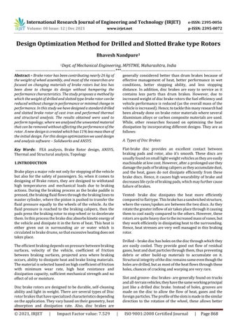
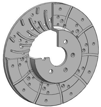
Fig 1:SectionviewofDrilledandslottedtypeRotor
A) Structural Analysis
Themodelofdrilledandslottedtypebrakerotorisdesigned usingSolidWorks.Inthis,amodelwascreatedbytakinginto consideration that most of the area is exposed to the convectionwhichwilltakeplacenaturally(byair).Moreover 32vanesareprovidedtodissipatetheheatrapidly. Theholesaredrilledsothatproperheatflowthroughthem takes place and minimum thermal stresses are generated withinthebodytoavoidconditionofwarpingandcracking.
Rounded holes are useful because the stress distribution occurs uniformly around the surface, and as there are no sharpedgesthechancesofcrackingarereduced.Thegrooves are provided on the surface of brake rotor to allow the outflowofdebrisandparticlesgeneratedbyfrictionbetween padandrotor.


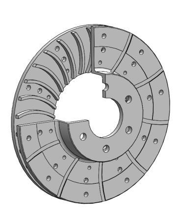
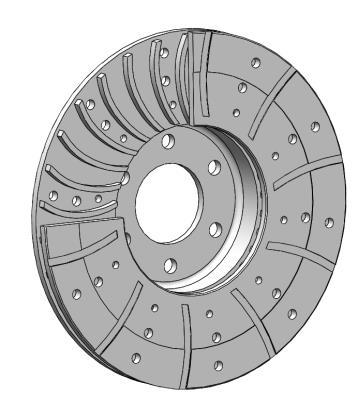
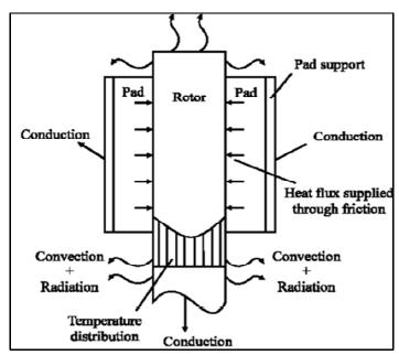
Fig 4:Modesofheattransferinbrakerotor.[10]
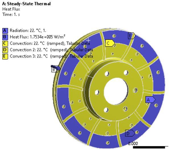
Fig 5:Appliedfluxonbrakerotor
International Research Journal of Engineering and Technology (IRJET) e ISSN: 2395 0056 Volume: 08 Issue: 12 | Dec 2021 www.irjet.net p ISSN: 2395 0072 © 2021, IRJET | Impact Factor value: 7.529 | ISO 9001:2008 Certified Journal | Page872
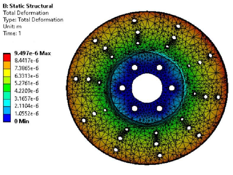
Fig 3:Resultsobtainedaftersolvingstructuralanalysis
The thermal analysis was carried under atmospheric conditionsat295Kor22˚C,wheretherotordissipatesheat bymeansofconvectionandradiationtosurrounding.Heat fluxof175.342KW/m2isappliedoncircularcrosssection wherethediscwillcomeincontactwiththepistoncylinder [4].Heattransferistakingplacebyconduction,convection andradiationshowninfigure.Thethermal conductivityis takenas52W/mKasthediscismadeofGrayCastiron.
samedirectionofvanesprofile,throughwhichinflowofair willhappen.
Fig 2:Appliedforcesonbrakerotor
Themaximumdeformationof0.009mmisoccurringonthe outer surface where the pads apply force to rotor and the leastdeformationistakingplace,neartheareaaroundfixed support.Thedeformationisdecreasingfromoutersurface towardshubareaandsimilartrendisseenatthebacksideof rotor.However,theequivalentstressconcentrationgoeson increasing from center of the rotor and becomes zero on outerperiphery.
B) Steady State Thermal Analysis

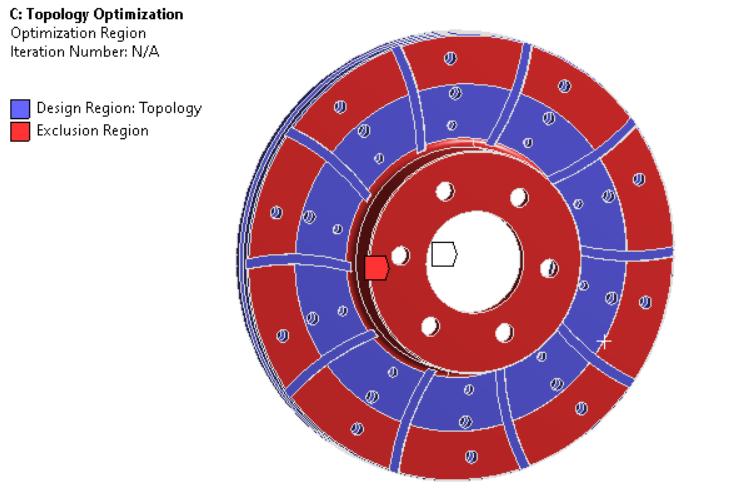
C) Topology Optimization Topologyoptimizationistoolthatseekstoidentifythebest materialdistributionwithinthebodyingivenconstraints. For,thisoptimizationourobjectiveistominimizetheweight ofbrakerotorwithoutdisturbingormakingminimalchange intemperatureanddeformationvaluesobtained.For,this analysis we are using ‘Topology Optimization’, module available in ANSYS 19. The initial weight of rotor was observedtobe6.89kg,whichsumsup toapproximately27 kgsforfourrotors. Firstly, for performing analysis we have defined our functionalandnon functionalareasshowninfigurebelow. Wehavedefinedfirstfunctionalareanearfasteninglocations wherethehubwillattachthebrakerotor.Secondfunctional areaisfixedwherethebrakecaliperwillapplybrakingforces to decelerate the vehicle. In these areas there will be no changeinmaterialdistribution.Thenon functionalareain our analysis can be seen in blue colour, where material removal will occur without effecting the temperature and deformationsignificantly.Wehavesetthepercentageofmass retaintobe75%asourresponseconstraint.
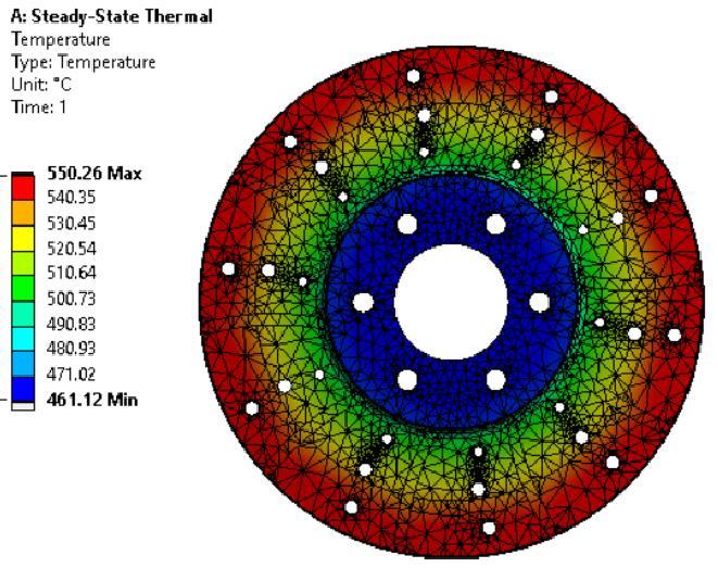
Fig 6:Resultsobtainedaftersolvingthermalanalysis
Fig -7:Functional(red)andNon functional(blue)areas
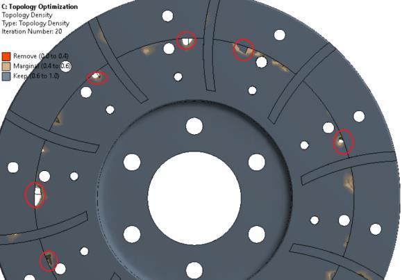
Fig 8:ResultsobtainedafterTopology
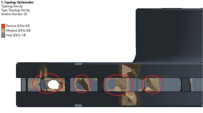
Fig 9:Frontareafromwherematerialcanberemoved Fig -10:Rearareafromwherematerialcanberemoved Fig 11:Vannedareafromwherematerialcanberemoved
International Research Journal of Engineering and Technology (IRJET) e ISSN: 2395 0056 Volume: 08 Issue: 12 | Dec 2021 www.irjet.net p ISSN: 2395 0072 © 2021, IRJET | Impact Factor value: 7.529 | ISO 9001:2008 Certified Journal | Page873
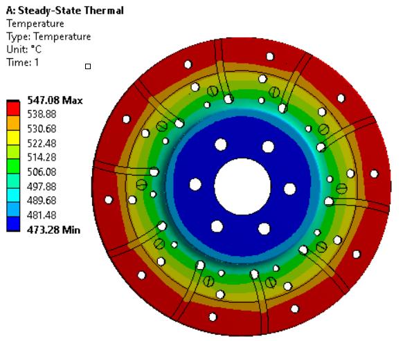
Themaximumtemperaturewasseenonthefunctionalarea ofrotorwhichstaysincontactwhenbrakesareapplied,it was550˚C.Itkeptondecreasingaswemovedtothecenterof thediscastheheatwasflownoutbymeansofholes,vents andothersurfaceswhichcameincontactwithairasthedisc rotated.Similarlyheatfluxwasobservedtobemaximumon middleareawhichisnon functionalandaccompaniesonly duringheatdissipation


International Research Journal of Engineering and Technology (IRJET) e ISSN: 2395 0056 Volume: 08 Issue: 12 | Dec 2021 www.irjet.net p ISSN: 2395 0072 © 2021, IRJET | Impact Factor value: 7.529 | ISO 9001:2008 Certified Journal | Page874
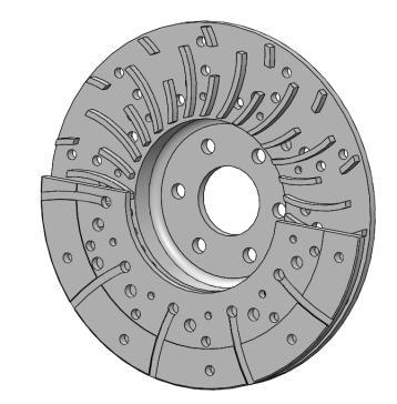
Fig -12:SectionViewofmodifieddesignofrotor
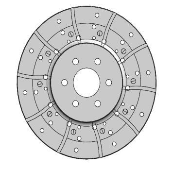
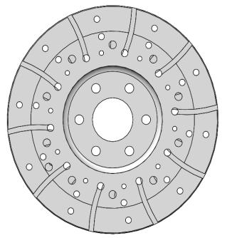
Fig 13:Frontandbackviewofbrakerotor
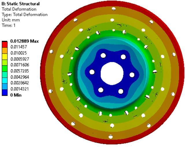
Fig 14:StaticStructuralAnalysisofModifiedbrakerotor
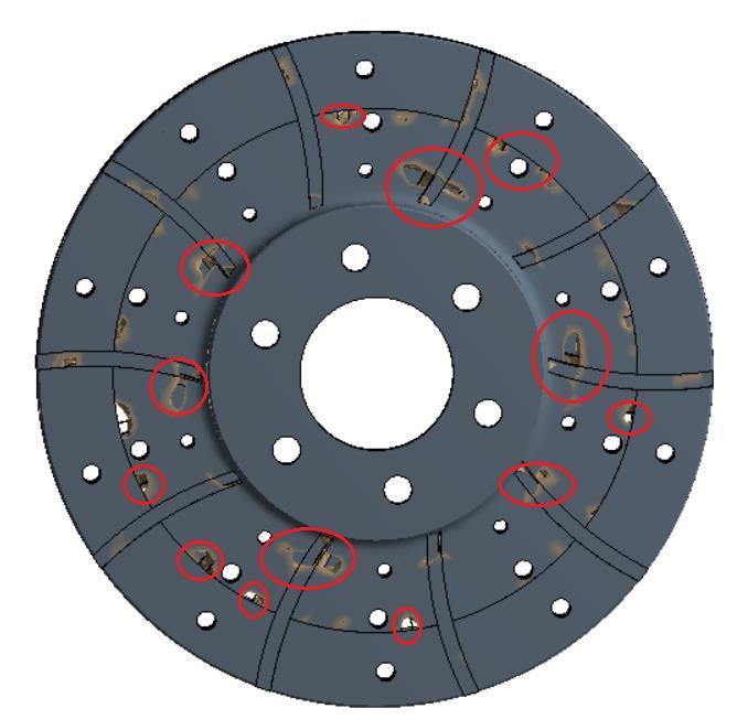
A maximum reduction of 14% of the mass can be done to achieve similar results of temperature and deformation. However,reductionineveryelementalmassisnotpossible duetomanufacturingconstraints.So,wewereabletoachieve 11% Fromreduction.theresultsobtainedwehavehighlightedtheareasby redcirclesasshowninfigurefromwherematerialremoval canbedone.Basedontheanalysisanewdesignwascreated byremovingmaterial.Structuralandthermalanalysiswas performedagaintoverifytheresultsandwhiledoinganalysis onmodifieddesignwekepttheinitialparameterssameas above.
Fig 15:SteadyStateThermalAnalysisofModifiedrotor 5. CONCLUSION After performing analysis on modified rotor design, the weightoftheslottedanddrilledtyperotorobtainedis6.15 kg,where750gmweightisjotteddownfrominitialdesign. Moreover, the maximum temperature and maximum deformation after analysis is 547˚C and 0.012mm respectively,whicharesimilartothereadingsobtainedin earlier analysis. The heat flux and equivalent stresses generatedarealsonearlysame.Therefore,fromtheanalysis we conclude that the new design is within safe limits of brakedesignandthismethodologycanbeusedtoperform analysisonothertypesofbrakerotorsandotherautomotive components.
REFERENCES [1] R.SKhurmi,J.KGupta“TheoryofMachines” Brakesand Dynamometers(S.Chand),ISBN:978 81 219 2524 2 [2] FredPuhn,“BrakeHandbook”(HPBooks,U.S.A,1985), ISBN:0 89586 232 8 [3] M.T.Milan,OmarMaluf,DirceuSpinelli,“Developmentof materials for automotive disc brakes”, ResearchGate January2004 [4] DaanvirKaranDhir,“Thermo mechanicalperformance ofautomotivediscbrakes.”,Elsevier July2016 [5] ThermalGuruMurthyNathi,TNCharyulu,“CoupledStructural/analysisofDiscBrake.”IJERT:2012 [6] Rudolf Limpert, “Brake design and safety.” (SAE International,U.S.A1999)ISBN:1 56091 915 9 [7] Aakash Jawla, Rahul Anand, Shobhit Agarwal,” Design and thermal analysis of brake disc for optimum performance.”, Vol.8. IJRASET April 2020, ISSN:2321 9563
ISSN:2278 0181 [10]
[9] Bangaru Bharath Kumar, “Thermal Analysis of Brake Rotor.”, May2021, F.Talati,. Jalalifar, “Investigation transfer ventilated disc rotor radial rounded of
with straight
vanes”, Journal
applied Sciences,8:3583 35922008
phenomenon in a
[8] Atharva Kulkarni, Rohan Mahale,”Impact of design factors of disc brake rotor on braking performance.”,
Vol.10.IJERT
of heat
Vol.9.IJERT June2020,ISSN:2278 0181
International Research Journal of Engineering and Technology (IRJET) e ISSN: 2395 0056 Volume: 08 Issue: 12 | Dec 2021 www.irjet.net p ISSN: 2395 0072 © 2021, IRJET | Impact Factor value: 7.529 | ISO 9001:2008 Certified Journal | Page875