Key Words: Sheet Metal Bending, CNC Bending, Die Shaving, Auxiliary Axes, Flange Length, Stopper Attachment, Press Brake, Collision detection, Energy mission, Amada, Hindustan Hydraulics, Delem Controller, Errors in CNC, Small Flange Bend, CNC Programming
International Research Journal of Engineering and Technology (IRJET) e-ISSN: 2395-0056 Volume: 08 Issue: 12 | Dec 2021 www.irjet.net p-ISSN: 2395-0072 © 2021, IRJET | Impact Factor value: 7.529 | ISO 9001:2008 Certified Journal | Page843 STUDY AND EXPERIMENTATION ON MINIMUM BEND POSSIBLE IN CNC BENDING
Abstract The paper discusses about the minimum possible flange length bend that is possible on conventional sheet metal CNC Bending machine. Generally, a bend of about 7 10 mm is possible on regular machine with standard dies (depending on machine), but sometimes Industrial manufacturing also requires lesser flange length bend, about 5 mm or less. In practice, the die of smaller width such as 8 mm is used in manufacturing, but changing the die and setup for, such condition, bending is expensive and time consuming which in fact raises the manufacturing prices for smaller bends. The paper focusses on the possibility and solution for the smaller bend using the die available with the CNC avoiding an expensive setup. For an example, a common die width of 14 15 mm which only allow bend flange length to 8 10 mm. Any bending below is not possible due to the collision between the die and stopper, ultimately stopping the machine. So, to produce bend with a flange length that is smaller than half the width of die, anexperimentationis conducted. The bendingoperationis thoroughly studied. A Number of 3 different CNC press brake model (sheet metal bending) are used in experimentation. Die Shaving, Auxiliary Axes Adjusting, Stopper Attachment are the method or solution that are proposed. The design, manufacturing and employment of each ofthe solution is done and a set of5 mmsample bend with each of the solution and on each of the CNC are performed and the result are noted down. Fairly, all the solutions on all the CNCs performed well and our aim of achieving smaller bends with Inexpensive die setups was successful.
1 4Bachelor of Technology in Mechanical Engineering, Vishwakarma University.
Sheet metal bending is an operation that involves using forces to change the shape of a sheet. This is done to achieve the desired form or shape needed for a manufacturingprocess. Inhistory,beforesteel cameintogeneral useduringthe latter part of the 19th century, curved structures were frequently constructed from iron, which is cast in liquid form in a curved profile or built up from wrought iron components, either with shaped web plates or in the form of lattice trusses. Because wrought iron was very soft, blacksmiths could curve small components by hot forging.Duringthe20thcentury,rolledsteel joistswere curved by metal benders for use as colliery arches to support underground workings. Hydraulic presses were usedinitiallytocurvethejoistsbuteventually,three roll bending machines were introduced for bending metal. Because joists have very thick webs, they are not susceptible to buckling during the bending operation. As early as 1910, bending equipment incorporating rollerswasusedtocurvebulbflats,bulbangles,andtees for marine use. During the period from 1930 to 1950, small curved steel components were also used in relatively simple building structures. Nissen huts, aircrafthangers,andDutchbarnsoftenhadasupporting structure of curved steel angles, tees or small rolled I sections. This is a brief history of the metal bending Metalprocessbending is a process by which metal can be deformed when applying force to the subject, which causes it to bend at an angle and form the anticipated shape, which often results in it being in a 'V' or a 'U' shape. A press brake is a tool used to bend sheet metal andusesapunchanddietodothis. The different types of sheet metal operations can fall under two different categories: cutting operations and formingoperations.
2. LITERATURE SURVEY Megson, T.H.G [1] Generally, a thin plate is defined as a sheet of material whose thickness is small compared with its other dimensions, but which is capable of resistingbendinginadditiontomembraneforces.Sucha plate forms a basic part of an aircraft structure, being, for example, the area of stressed skin bounded by adjacent stringers and ribs in a wing structure or by adjacentstringersandframesinafuselage.Thischapter investigatestheeffectofavarietyofloadingandsupport conditions on the small deflection of rectangular plates andpresentstwoapproaches anexacttheorybasedon the solution of a differential equation and an energy methodrelyingontheprincipleofthestationaryvalueof the total potential energy of the plate and its applied loading. Two types of solution are obtainable for thin plate bending problems by the application of the principle of the stationary value of the total potential energy of the plate and its external loading. The first, in which the form of the deflected shape of the plate is known, produces an exact solution; the second, the Rayleigh Ritz method, assumes an approximate
1. INTRODUCTION
***
Suyant Dharwarkar1, Abdulhasnain Akodiyawala2, Amit Jadhav3, Aliasgar Nagdawala4

deflected shape in the form of a series having a finite number of terms chosen to satisfy the boundary conditions of the problem and also to give the kind of deflectionpatternexpected.
Guhr et al. [2] Load and shape optimisation are applied to the process of air bending to optimise the damage stateintheformedcomponent.Theenhancedprocessof elastomer bending is optimised, which yields a reduced damagestateduetothesuperimposedradialstressesin thecriticalareaoftheformingprocess.Theoptimisation presented here is twofold. First, the elastomer is replaced by nodal loads to generate optimised loads for a reduced damage state. Second, the elastomer itself is optimised via shape optimisation by adjusting the layer for two kinds of elastomer of varying stiffness. The optimisation is accomplished with the commercial FEM software Abaqus as the solver for the mechanical problemandMatlabisusedforoptimisation.
International Research Journal of Engineering and Technology (IRJET) e ISSN: 2395 0056 Volume: 08 Issue: 12 | Dec 2021 www.irjet.net p ISSN: 2395 0072 © 2021, IRJET | Impact Factor value: 7.529 | ISO 9001:2008 Certified Journal | Page844
Shantanu Garad et al. [5] Presently, bending machines has tremendous use within the field of workplace. The bending machine is one among the foremost important machine in sheet work shop. Its primarily designed for bending.Thebendhasbeenmadewiththeassistanceof press which exerts large impact force on the work clampedonthedie.Manualbendingmachinetakesextra time and also take more efforts to bend the work piece. Hence,ittakeslongertimeforproduction.Thereslackof reproducibility, repeatability, and effectiveness. It also fails to satisfy customer satisfaction. So, our aim is that thebendingmachineismeantinsuchhowthat,itworks automatically. The automation strategy, when implemented give rise to reduced cycle time, costs and improvedproductquality.Furtherprobablebenefitsare increasedoutput,easeofoperationandincorporationof business systems. This bar bending machine replacement for manual machine and its a semi automaticonebyusingelectrical motor, gear box etc.,it simplify the manual work and economic wise by reducingthelabor.
Kumar et al. [3] Thebookisbasicallywrittenwithaview to project Computer Numerical Control Programming (CNC)Programmingformachines.Thisbookshowshow to write, read and understand such programs for modernizating manufacturing machines. It includes topics such as different programming codes as well as differentCNCmachinessuchasdrillingandmilling.The book is basically written with a view to project Computer Numerical Control Programming (CNC) Programming for machines. This book shows how to write, read and understand such programs for modernizating manufacturing machines. It includes topics such as different programming codes as well as differentCNCmachinessuchasdrillingandmilling. Li et al. [4] The bending sheet metal inevitably exist bendingerrorsincludingangleerror,linearityerrorand length error of sideline for reasons that the structure of press brake, the manufacturing precision of press brake and mould and the inhomogeneous characteristics of processed sheet metal. The processing errors of sheet metal can affect the assemblage, increasing subsequent repairtothemoldandformingcalibration,extendingthe product development cycle, restricting the further promotion and application of bending forming, especiallyontheforminghighstrengthandhighspring back sheetmetal.ThePBH110 3100CNCpressbrakein Jiangsu Yawei Co.Ltd. is studied to increase the bending precision of press brake in this study. The bending errorsinpressbreakareanalyzedindepthaccordingto the elastic mechanics theory, and the rule that the manufacturing precision of press brake affect the press precision is educed. The analysis results have real significance on improving the press precision and reliabilityofpressbrakes.
3. MACHINE REVIEW
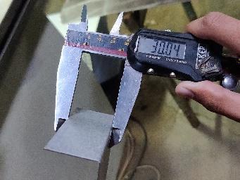
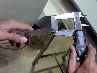
sets of Die and Punch are provided with each machine. The width of the Die and Size of Punch also vary according to the Manufacturer. Width of die is standard for a specific CNCs. The width ranges from 12 mm 15 mm depending on the tonnage and operation, the machine can perform. These machines are also equippedtoperformhemmingandlargeradiusbending (curveforming)operations.
This section discusses about the CNC Machines, used in the Experimentation. The specification and the model make of the machines are reviewed briefly. Three modelsof machinesare beingused for experimentation. They all are CNC press brake with Indian and Foreign manufacturerstandards. All the CNC machines listed are used for Sheet Metal Bending operations form Material range of MS, SS, Aluminum, GI, etc. The Thickness of the Sheet that can be Bended,Rangesfrom 0.5 mm to 5 mm,all machines Bendconsideredofdifferent angle can be achieved either by changing the Die specifications or the bending Allparameters.threetypesofbendingcanbeperformedintheCNCs, Coining, Bottoming and Air bending. The Bending method used in the experiment is restricted to Air bending Standard.
All the machines are sold with sets of dies and punches having different sizes for standard quality throughout themanufacturingindustries.
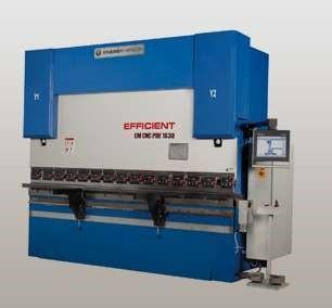
ENERGY MISSION PBE 315 [6]
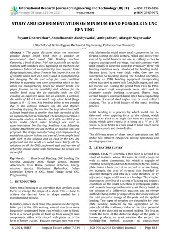
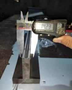
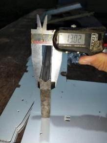
Fig-1: DieWidthofCNCmachines,fromlefttoright,for EnergyMission,HindustanHydraulicsandAmada.
International Research Journal of Engineering and Technology (IRJET) e ISSN: 2395 0056 Volume: 08 Issue: 12 | Dec 2021 www.irjet.net p ISSN: 2395 0072 © 2021, IRJET | Impact Factor value: 7.529 | ISO 9001:2008 Certified Journal | Page845
PBE 315 CNC Press brake is a model of Energy mission, an India (Ahmedabad) based CNC machine manufacturer.Thespecificationsofthemachinesare, Ithas3Automatedaxes,namelyY1,Y2,X,and 1manual axis, Auxiliary axis. The Auxiliary axis can be manually adjustedforthestopperpositionvertically.TheXaxisis for the stopper movement in horizontal to and fro direction for the flange length of bend. The Y axis is for the movement of punch in the vertical direction. The ControllerinthemachineisDELEMDA53T,anadvance TouchscreenModel. There are 4 stoppers arrangement with accuracy of ±0.01mm.thebedlengthis1500mm.thecapacityofthe machine is 30 TON. Press is powered by a 3 phase AC motor of 3 HP. System pressure of about 150 kg/cm2 . Operation type is Electronic Foot pedal operation. The Movement of the press occurs in Vertically downward direction.
Fig 2: EnergyMissionPBE315 [6]
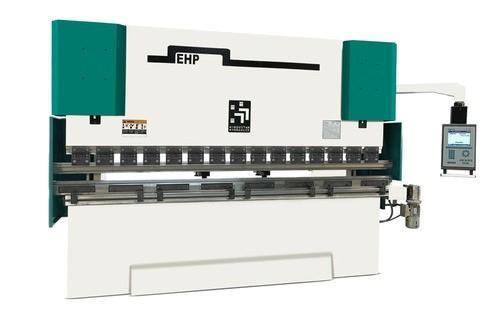
HINDUSTAN HYDRAULICS EHP80 25/20 [7] Fig 3: HindustanHydraulicsEHP8025/20. [7] EHP 80 25/20 is the model CNC press brake of HindustanHydraulics,Punjab,India. ItsworkingissameastheEnergymissionPBE315with a controller of, DELEM DA 52S button Operated, it also has3automatedaxesandonemanualauxiliaryaxisand 4stopperarrangement. The movement of the press is vertically downward. Accuracy of ±0.01 mm and bed length of 2500 mm. the capacity is higher, 80 TON with 7.5 KW 3 phase AC motor.AlsoElectronicfoot pedal andNohanddetection system.
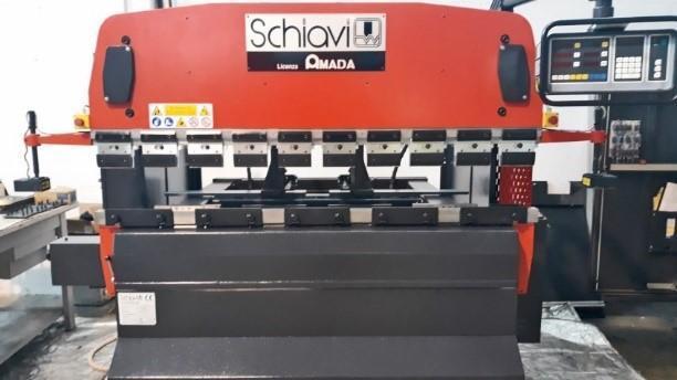
AMADA SCHIAVI RG 35 20 [8] Fig-4: AmadaSchiaviRG35 20. [8] Amada Schiavi RG 35 20 is a CNC press brake model fromaAMADA,aJapaneseCNCmanufacturer Controller offered is Master Task 84 with 4 stopper arrangement and 4 automated Axis system. The Auxiliary Axis Automated movement provides the stopperCalibrationwithaccuracyandfast.Bedlengthof 2000 mm. 35 TON capacity operated with lever pedal arrangement. The difference between the other machines and this machine is that the vertical upward movement of Die towards the punch. This machine comes with human hand detection system which can be manuallyoverrideforspecialusage. Mostly these three machine are used in the experimentation and the further details of the machines
4. PROBLEM STATEMENT
Generally,abendwithflangelengthgreaterthanthehalf thewidthofdieispossible.Butsometimesmallerbends are required in manufacturing Industries. This is not possible with the standard CNC bending techniques as the Flange length smaller than the half width of the die, DetectsCollisionbetweenstopperanddieandoperation So,halts.theproblemstatementis, To provide a solution to Bend a flange length, in Sheet Metal, which is about 1 2 mm smaller than the Half widthofdiewithoutCollisionDetection.
5. METHODOLOGY
Thisparticularsectionofpaperdiscussesthemethodsor Regular procedure used for sheet metal bending using CNCpress brakeinmanufacturingIndustry.
1.3.MarketSurveyandMachineReview.
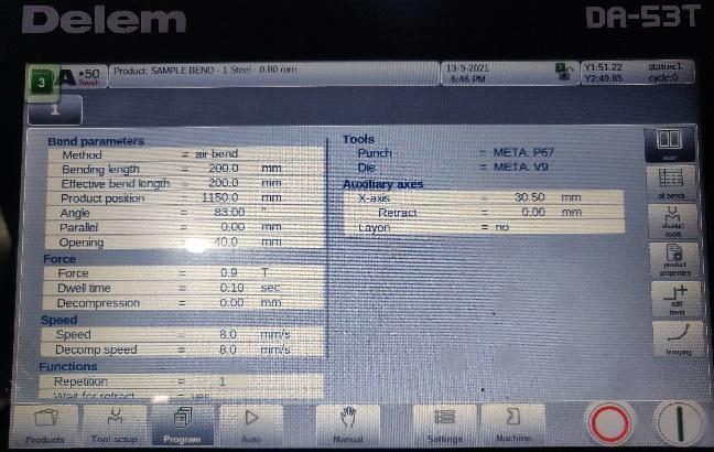
Fig-6: ProgramEditScreen.
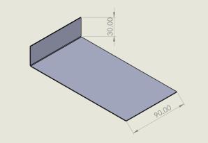
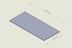
The method or procedure is basically one and same for all the press brake with slight difference in presetting andUserinterfaceoftheprogram. Thedraftingofjobinourexampleisshowninfigure.The machine used is Energy Mission PBE 315 with DELEM DA53T. Fig 5: DraftingwithFlatView
1.7.Drafting all the research, methods, Modeling, ExperimentationandResults,withConclusion.
The program is named as SAMPLE BEND with die and PunchofP67andV9respectively.
1.2.Detailed Study of Sheet Metal Bending Terminologies,Methods,Design.
International Research Journal of Engineering and Technology (IRJET) e ISSN: 2395 0056 Volume: 08 Issue: 12 | Dec 2021 www.irjet.net p ISSN: 2395 0072 © 2021, IRJET | Impact Factor value: 7.529 | ISO 9001:2008 Certified Journal | Page846 can be accessed through the official sales and info websites of the respective CNCs given in the Reference SectionBelow.
1.1.IdentificationofProblemStatement.
6. METHOD
1.4.Designing, Prototyping and Solid Modeling of Solutions. 1.5.ManufacturingandImplementationofSolution.
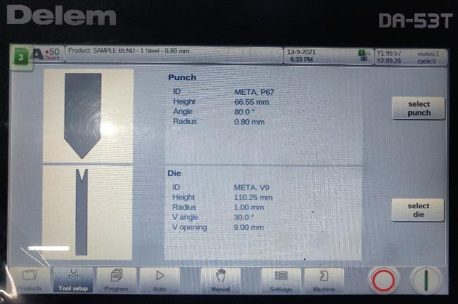
Theoperatorfirstandforemoststudiesthedrawingand select the right die and punch for operation. Different sizes of die and punch setting comes with the machine. The particular bend length of the job is used to determinethelengthofdieandpunch.thebendlengthis about 90 mm so the die close to the length is 100 mm. Theselecteddieandpuncharemountedonthemachine and tighten slightly with the allen locating pins. Punch and die are still not in center position and punch has clearance with the clamping which will cause the punch to move while bending which is quite dangersome for thejobaswellasoperator.Soapre operationprocedure is carried out in which the machine is set to Adjust setting and the operator starts the machine and moves the punch to its bottom dead position until the lowest endofpunchtouchesthelowestendinthecavityofthe die, in simpleword thepunchanddie meetsanda little pressureisapplied.Theseoperationrequiresmuchskill. Operator is provided is a manual containing Y Axis valuesrequiredwhilepressurefittingtheDieandPunch. operator applies the pressure manually until the screen shows the Y axis value, given in the manual. The operator removes the pressure, further pressure will damage the die and overall, the machine. Now, the die and punch are tightened thoroughly. This operation ensurestheprecisemountingofdieandpunch. The next step is Programming the parameters for bending. Previously G codes were used for programming. But the advance Delem controller UI providesanapplicationforcreatingprogrambyinputof requiredbendingparameters.
1.6.Testing,ModificationandNotingdonetheResults.
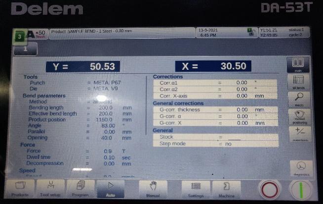
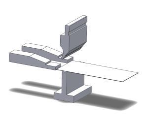
Oncethepresettingisdonethemachineisagainchanged from Adjust to Auto setting and the program is runned. The machine starts to reference the X axis in which the stopperisreferencedtotheextentandthentothestated X axis position in program. Then the machine is ready for Theproduction.operatorrest the sheet on the die and touches it to the two stopper end as shown in figure. All the Step in theOperationareshownStepwiseinFiguresbelow
Fig 7: DieselectionScreen.
Fig 8: AutoProgramRunScreen.
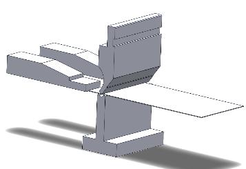
Fig 10: 4Stepinbending(Clockwise)
International Research Journal of Engineering and Technology (IRJET) e ISSN: 2395 0056 Volume: 08 Issue: 12 | Dec 2021 www.irjet.net p ISSN: 2395 0072 © 2021, IRJET | Impact Factor value: 7.529 | ISO 9001:2008 Certified Journal | Page847
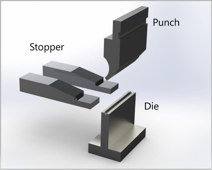
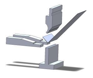
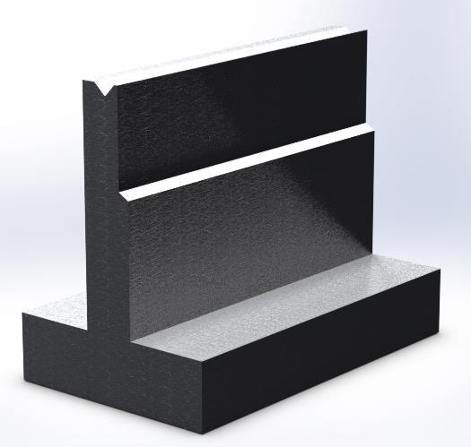
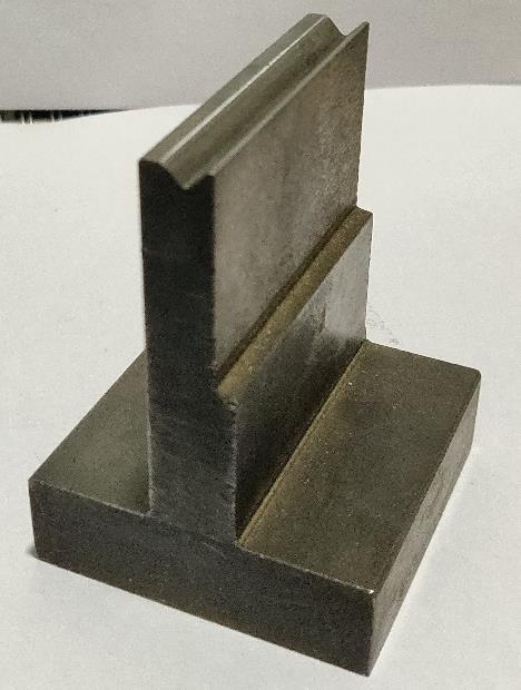
The model of the setting of die, punch and stopper is shownbelow.
Operator provides the parameter of flange length in AuxiliaryAxes30.50mminwhich+0.50mmismachine Error Factor for Respective machine, 90o bend angle with 7o ErrorFactorofRespectivemachine,0.8mmand GI is the thickness and Material of the sheet selected, bendradiusof0.8mm,typeofbendingisAirBending,a 40 mm opening between die and punch for smoother removal of job, etc. all the bending formulae and factor arealreadyprogrammedinthesystembymanufacturer and simple input creates the program makes the machineeasytouseandtimesaving. SomeadditionalparametersaredecidedbyProgramlike 0.9 Ton of force, Dwell time of 0.10 sec, 200 mm of bendingandEffectivebendinglength. The Red button is for programstop and Green button is forproductiononthescreen.
Thentheoperatorpressesthepedal.Whichoperatesthe strokeofmachineandthepunchmovesdownwardsand bends the sheet as clearly shown figure above. Keeping the Center line of Die as datum, the Machine positions the stopper precisely at the input flange length input in programming,sowhenthebendisperformedtheflange lengthofthebendwillbeaccuratelyastheinputgivento the Themachine.bending is a forming operation in which the pressure is applied by punch to the sheet metal the metal takes the shape of die cavity. The die and punch are always of harder material (hardened carbon steel) thentheworkpieceforlongerlifecycle.Oncethebendis
Fig 9: 3DmodelofDie,PunchandStopper.
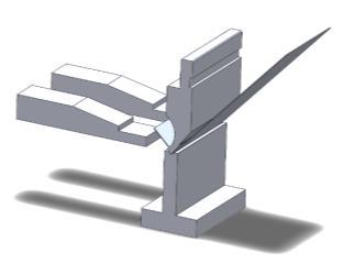
International Research Journal of Engineering and Technology (IRJET) e ISSN: 2395 0056 Volume: 08 Issue: 12 | Dec 2021 www.irjet.net p ISSN: 2395 0072 © 2021, IRJET | Impact Factor value: 7.529 | ISO 9001:2008 Certified Journal | Page848 completebythemachinethenthepunchrisesandresets itself for the next bend cycle. In air bending the punch and die virtually do not touch each other at all but the punch comes down to the die and stops perfectly about the thickness of sheet, in our case 1 mm. These makes the operation quiet safer for MS, GI and Aluminum, this setting proves effective with these materials because they arecomparativelysoft. Butfor material likeSS and HighcarbonSteeltheAirbendingisnotsoEffectiveand Requires other bending techniques like Bottoming, whichcanalsobedoneontheSameCNC,butwillnotbe coveredinthesepaper.
8. SOLUTIONS AND EXPERIMENTATION
7. PROBLEM DEFINITION
This problem is also true for Hindustan Hydraulics and Amadaaswell.So,asolutionisrequiredforBendingthe sheettoaflangelengthlesserthanhalfthewidthofdie. The proposed Solutions are discussed in the sections below.
Different solutions are proposed and the solutions are considered with respect to all three CNCs, majorly the EnergyMissionmodelandforsimpleunderstandingand simplicity a single example is performed in all cases to getrequiredresults.A5mmflangelengthbendistaken asconstantexamplethroughoutthesolutions
An approximate flange length of 7.2 mm can be performed on energy mission model with about 14.30 mm width die and standard settings. The bend any smaller shows a collision error. The main problem with
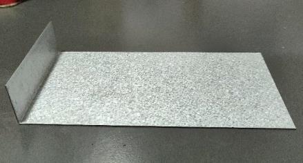
Fig 11: ActualSample(Post Operation).
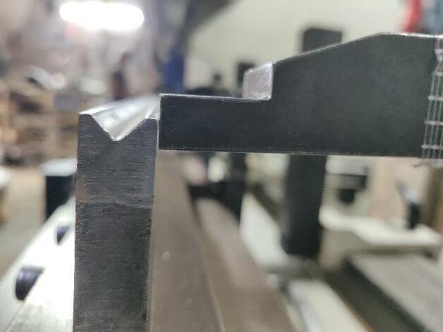
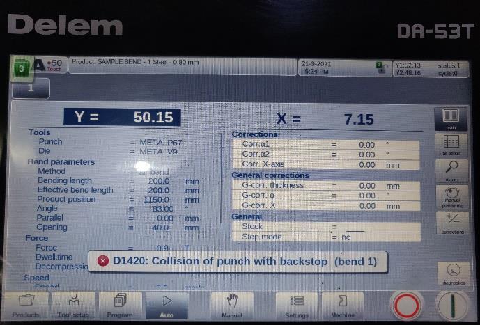
ThesesectionDiscussesthemainproblem,inlength,for whichthesolutionsaretobeIntroduced. For a standard machine, in standard practice, with the provided standard die width, a flange length of about half the width of die is possible. For instance, In Energy missionthediehasawidthofabout14.30mm,soabend with about 7.2 mm flange length is possible on Energy missionusingthegivendie. But, a bend, smaller than 7.2 mm is not possible, as the stopper setting for smaller bend, collides the stopper with the die and as the machine detects a minute back pressure due to collision which halts the machine immediately. So a smaller flange length bend does not seem possible with this particular setup. But, in the manufacturingindustrysmallerbend(flangelength)are Torequired.understand the problem more effectively a practical approach is used. In sample example above, the 30 mm flange length bend was explained. The die of 14.23 mm was being used in Energy Mission CNC. All the parametersandexplanation arebasedonthiscaseonly. Any bend above 30 mm is possible until the obvious constraints, but below 30 mm, the lowest in the case, is up till 7.15 mm only (which is half the width of Die). If the Input of X axis is given to about 6 mm the stopper will approach 6 mm but as the die material of 7.15 mm width from the origin or central axis of CNC machine restrictsthestopper movementany further asshown in thefigurebelow. Fig-12: CollisionofStopperandDie. Thereoccursacollisionbetweenthedieandthestopper anda littleback pressureto xaxisisinducedwithstops the machine (halts the electric pump and seizes all operation). A prompt is displayed on the display of machineasshowninfigure. Fig-13: Prompt(backstopmeansstopper,thevalueofx axisistrueandnoerrorfactor)
8.1
There are two possible methods to shave the die material accurately and precisely, one is milling of the dieandanothermethodisEDM/Wirecuttingofdie.Both the methods have its advantages and limitations. As in EDMcutting,dieismoreaccuratelymachinedcompared tomilling,alsothesurfacefinishishigh,thedrawbackof EDM cutting is, it is recommended only for shorter length die as EDM has cutting range of 150 200mm lengthalsoitisquiteexpensivecomparedtomilling.On the other hand, milling can be performed on larger die length,alsoitiscomparativelycheaperthanEDM. After the die is machined/ shaved it has a width of 4.51 mmfromthecenter.Aspreviously,usingthedieallowed only 7.2 mm bend but now the range of bend has increased by 2.64 mm. A sample bend for 5 mm is programmedandtheshaveddieismountedontheCNC, nowasthestopperapproaches5mmandstopat5 mm which still leaves about 0.49 mm clearance between die andstopperfaces and nocollisionisdetected.Thebend is successfully performed. The same technique is used forotherCNCwithabout4.7mmshavefor15.02mmdie of Amada. The same sample bends were performed on theAmada,givingsuccessfulresultstoo 8.2 AUXILIARY AXIS ADJUSTMENT
In this Approach, a bending method is introduced in whichsmallerbendscanbeproducedwithoutdamaging or counter fitting any parts in the machine. There are different axes in CNC press brakes, vertical Y axis and horizontal X axis and a Third axis called the Auxiliary axis. This axis is used for the vertical movement of stopper.Insome pressbrake,likeHindustanHydraulics andenergymission,theauxiliaryaxisismanualorsemi automated. But also, in some press brakes, like Amada, the auxiliary axis is automated. The auxiliary axis movement can be used to determine the exact positioning of stopper contact surface for different orientation of sheet metal Workpiece. An Auxiliary Axis Adjustment is applied to achieve desire results. As the name suggests, the stopper axis is adjusted manually or by Input and stopper is step in desired position for bending. Amada is used in Implementation and explanation for this Approach as Amada has automated AuxiliarywhichmakesitprimeExample. Amada uses a different method for sensing collision detection. The stopper is actually a loose piece which is attached using a ball joint release, so if the stopper face clashes with the die material in front, due to sudden pressure the stopper detaches safely and pushes itself out of place preventing from further damage to the die ormachineaswhole. As the programming for smaller bend does not hinders with the machine working, so X axis can be set to 4 7 mm bend. All the other parametric input will be the
Cuttingofdieisnotaneasyoperationasthediematerial ishighqualitytoolsteelwhichcannotbecutbystandard milling or grinding operations. As the die width is comparatively small, the operation needs to be precise andaccuratetoatoleranceofabout~0.01mm. In this case, Advance milling is used as to shave the material. An advance tool material milling operation is performed to remove about 2.64 mm material of die from the edge of die in transverse direction which will cut about 2.64 mm material of top land and leave about 1.36mmoftoplandforthe purpose.This will makethe total die width to about 11.66 mm. The milling is done usingCNCMillwithasidemillingcutterin2passeswith the first rough pass of 2.5 mm depth of cut and a finishingpassof1.4mmcutandtoalengthof100mmin horizontal direction and about 26 mm in vertical direction. Thefigurecontainingthemodel oftheshaved Dieisgivenbelow.
International Research Journal of Engineering and Technology (IRJET) e ISSN: 2395 0056 Volume: 08 Issue: 12 | Dec 2021 www.irjet.net p ISSN: 2395 0072 © 2021, IRJET | Impact Factor value: 7.529 | ISO 9001:2008 Certified Journal | Page849
collision error is the back pressure exerted on the stopper by the die which the machine detects and stops theoperation.
Fig-14: ModelledDIEafterShaving Anymaterialremovalfurtherthan2.64mmwilldamage the integrity of the die and any lesser removal will not letthesolutiontoserveitpurpose.
The die material restricts the moment of stopper. So, an approach of removing the material, that collides with stopper, is proposed. For bend of about 5 mm to be achieved, a 2.2 mm material (approx.)will be neededto be removed. So for clearance and manufacturing tolerances a 2.64 mm material is shaved. The trimming isdonefromoneedgeofthedietowardsthecenter.Any one edge could work as the die is symmetric. But the amountofmaterialremovalshouldbecriticallydecided. The die’s dimension, terminology and construction is thoroughly studied. The die’s valley or cavity is most important and critical area of die and any alteration in that part will damage the die and ultimately the operation. But the die has enough area to work as well. There is an 8 mm flat land on the die which is used for straight placement of flat sheet for operation. So being abletouse4mmflatlandfortrimming,thepropertiesof thevalleyanddiearenotthatmuchhampered.
DIE SHAVING
The attachment is mounted on stopper as shown in the figure. This virtually increases the stopper Length by 2
In this approach, an external Attachment is used for the smaller bend to performed. Virtually the workpiece needs to positioned, for a 5 mm bend, at about 2 mm offset from the stoppers extreme position in a conventional CNC press brake with collision detection setting. Explaining with an example, the of Hindustan Hydraulics having 13.02 mm Die width will have minimumpossiblebendof7mm,anyleesthanthatwill detect collision. So, virtually we need the stopper at 5 mmXaxiswiththemachinedetectingthecollision.This is only possible by passing the machine setting and introducing an Attachmental Piece which will act as an offsetof2mmforthebendtobepossible.
International Research Journal of Engineering and Technology (IRJET) e ISSN: 2395 0056 Volume: 08 Issue: 12 | Dec 2021 www.irjet.net p ISSN: 2395 0072 © 2021, IRJET | Impact Factor value: 7.529 | ISO 9001:2008 Certified Journal | Page850 same as a conventional bend setting requires. Just, in this case, the auxiliary axis is manipulated to a setting where the bottom face of stopper just rest on the top surface of die, when the X axis is approaching the extreme position. Now as there is no possible way for collisionbetweenstopperanddiethecollisiondetection does not occur and the machine operates as general. About vertical 0.2 mm of clearance is kept so that there is no rubbing friction and also accounts for machine error. The clearance is prescribed as, for 1 0.8 mm sheet, it is kept 0.2 mm which gives about 0.8 0.6 mm contact area between sheet and stopper. Also for 2 mm sheet the clearance can be set to 0.6 mm. It should be keptinmindthatonlyabout2 3mmexcessofstopper material rests on die, flange length of 4 7 mm. the settingisshowninthefigurebelow.
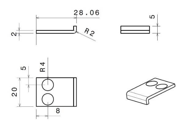
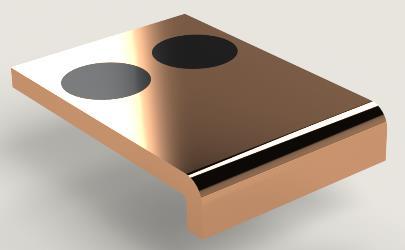
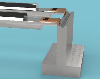
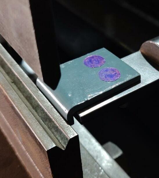
The Attachment is made about 2 mm Thick, 20 mm in widthand28mmLong.Thematerialusedis42CrMoDie Steel and the Attachment is manufactured using Wire CutEDMprocess.Theclampingonstopperisdoneusing magnets. Two fairly strong Button magnets with 8 mm diameter and 2 mm thickness are press fitted on the attachment. For other bending operations the machine needstoworkasusual,sothedrillingortamperingwith stopper was prohibited for better quality of working of machine.so,magneticclampingwasthefeasiblesolution which does not physically tampers or hammers the stoppersintegrity Fig 17: Attachment. Fig-18: AttachmentonAmadaStopper(left),Attachment onHindustanHydraulicsStopper(Right).
8.3 STOPPER ATTACHMENT
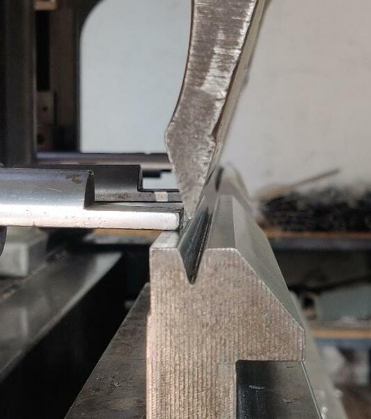
Fig-15: AuxiliaryAxisAdjustment. Anymaterial further will crushthestopperbetweenthe die and punch. operator needs to be very precautious while setting the auxiliary axis. As per this setup on Amada, Flange length of 7 4 mm is possible and successfulwithoutDamagingorcounterfittinganyparts ofthemachine. ForAmada,theAuxiliaryaxisbeingcomputercontrolled speeds the operation by just an input. For machine like energy mission and Hindustan hydraulics the auxiliary axis is manual and hence the setting is done by using Vernier and gauges and time for calibration is considerable.
Thedesign,ModelingandPrototypingoftheattachment is done by keeping in mind the terminology and design of Stopper and machine. The material of stopper is also considered. A prototype design of attachment is shown infigurebelow Fig 16: AttachmentGeometry
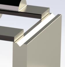
Some testing was done on Hindustan and Energy Mission as well. This method was quite promising on Amada CNC. Amada having the feature of Automated Auxiliary Axis of Stopper, which only required the operator to note down the auxiliary calibration value of stopper for Smaller bends, once. After that only the operator needs to punch the value during the programming. The Actual Setting of Die and Stopper Using Auxiliary Axis method for Amada is shown in the Figurebelow.
Fig 20: ActualFigureofStopperarrangementonDie usingAuxiliaryAxisAdjustmentMethod.
International Research Journal of Engineering and Technology (IRJET) e ISSN: 2395 0056 Volume: 08 Issue: 12 | Dec 2021 www.irjet.net p ISSN: 2395 0072 © 2021, IRJET | Impact Factor value: 7.529 | ISO 9001:2008 Certified Journal | Page851 mm,so,nowanyinputtothestopper’ s Xaxiswillactas ( )2 mm for the flange length. For example, if we input 10mmonXaxis,theStopperWillExactlystopat10mm XaxisbutduetotheAttachmenttheFlangelengthofthe bend will come out to be 8 mm. Also the attachment is not on the collision path to the die, which allow the Attachment Surface to move over the Die with enough Clearance. This finally helps in Bends like for 15 mm widthofdie,ifthebendrequirementis5.8mmtheXaxis value will be 7.8 mm, which clearly predicts that there should be no collision and a successful bend of 5.8 mm canbemade,iftheAttachmentismounted.
9
Figure 12 shows the Arrangement without the Method beingusedwhichResultsinCollisionoftheStopperwith Die.AndFigure20aboveshowstheuseofAuxiliaryaxis method and preventing the collision between die and stopper and successfully completing the operation. This method works in multi bend programme as well, but drawback is that considerable long flange lengths bend, example 100 mm and more, are not Suitable as the sheet metal slips below the stopper due to its own weight.ThemethodhassameresultswiththeHindustan Hydraulics and Energy Mission CNC, but only problem therewastheAuxiliaryaxiswasmanual.Sotheoperator needed to calibrate the axis using measuring tools and thistookquitesometime whichdirectlyaffectsthecost of manufacturing. Also this problem of calibration was not a onetime thing in case of Hindustan and Energy Mission.Ithadtobedoneeverytimethedieisreplaced
The material for Attachment is chosen as tool steel purposelyasit will beinSimultaneous Contact with the SS or MS sheet and over time any Softer material will degrade. No other conventional Manufacturing Techniqueisrecommendedandheattreatmentismust. RESULTS AND OBSERVATION
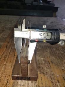
A set of sample bend of 5 mm Flange length were performed using all three Solution on every CNC press brake.Theresultswereobservedandnoted. The die shaving method was tested on energy mission and Amada. Hindustan Hydraulic was neglected as the thicknessof flatlandonthe dieof Hindustan hydraulics was less than 3 mm. The availability of Flat land for shaving, in case of Amada and Energy mission was high which increased the range of the solution. The Test bends had Considerable Accuracy. The below figure showstheshavedDieofEnergyMissionwith2.64mmof shavedfaceononeside. Fig 19: ActualShavedDieofEnergyMission. The solution is quite suitable in General Practice as no extra equipment setting is required. Also the same shaved die can be used for bends with any flange lengths, so multi bend operations is supported by this method. This works as an Excellent Advantage of the solution. Sometestingonmultibendoperationwasalso successfully performed for checking the speed and accuracy of machine with the shaved die. The main drawback ofthis solutionis, thatthe integrity of the die decreases. As the die, further of shaving, was rated by the manufacturer for about 3 4 mm sheet thickness bending. After shaving the die’s rating is considerable dropped to 2 mm sheet thickness bending. This is true for Energy mission as well as Amada. The Amada Die Showed Better results in Bending Cycles than Energy Mission. The Shaving Operation of dieisalsoExpensive, weather using Wire cut EDM or Advance milling. This alsoactsasadrawback.
Auxiliary Axis Adjustment was mostly tested on Amada.
12.1.1.6Double checking all the Clamping Bolts, programme inputs, Workspace Environment beforestartingtheproduction.
11 ACKNOWLEDGEMENT
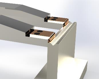
Fig 21: ActualSettingofAttachmentonStopper.
Attachment Method several Test bend were performed on Amada and Hindustan Hydraulics. All the bends Produced Satisfactory results. Several Design of Attachment were tested from which the Proposed Attachment Design was the most Economical and Simple. The material of Attachment 48CrMo is a tool steel with high hardness to begin with which increased the Life of Attachment. All type of bends, smaller or Larger, can be produced using this method as the only variationwillbethe( )2mmOffsettothedesiredflange length should be the input. Magnetic clamping turned out to be great as the Attachment would hold its place correctlyandmountingandUnmountingwasquieteasy. The Attachment surfaces which remain in contact with the stopper surface are precisely machined and surface finished. Manufacturing and material selection is expensive, but a onetime Investment. As the stopper design of Energy mission is Not compatible with our design of Attachment, this solution did not work well with Energy mission model. But a specific design of attachment for specific models of machine is also an option. The attachment was used for about 100 cycles and not a scratch on workpiece or attachment was observed.
The objective of the experimentation and the paper was toderivesomesimplesolutionsfortheproblemfacedin manufacturingofsmaller bendsusingconventional CNC press brakes. The solution of Die shaving turned out to be the most compatible with Energy Mission. Auxiliary Axis Adjustment showed higher compatibility with Amada Variant. Stopper Attachment Method was useful for Hindustan as well as Amada and to some extent Energymissiontoo.So,thistellusthatthecompatibility of every solution proposed can only be Stated by study theParticularCNCpressbrakeinuse. There are currently many solutions for the same problem like using a Die having smaller Width to begin with, special purpose CNCs for small bend Operations. But this solution itself are quite Costly and can only be preferredinverylargescalemanufacturing.Oursolution is Better suited for Small scale manufacturer using CNC Bending. Our solutions are proposed, keeping in mind the Investment Cost, Tampering Constraints, Skill of Operatorand precision ofoperation for small ScaleCNC users. The overall Results of all solution with Different CNC was Quite satisfactory to the Small scale manufacturingStandardsRequiredbytheIndustry.
WhilePerformingtheExperiment,usingtheCNCs,some BasicSafetyMeasureswerefollowed, 12.1.1.1Wearing Rubber Gloves while handling Sheet metal. 12.1.1.2Short Sleeved Clothing or Apron were used whileoperatingtheCNCs.
12.1.1.5Strictly Avoiding and part of body like finger or hands to come in contact with the CNC bend volume,whilethemachineisOn.
International Research Journal of Engineering and Technology (IRJET) e ISSN: 2395 0056 Volume: 08 Issue: 12 | Dec 2021 www.irjet.net p ISSN: 2395 0072 © 2021, IRJET | Impact Factor value: 7.529 | ISO 9001:2008 Certified Journal | Page852 or re mounted on CNC. This seems to be the main drawback of the solution that the method is only compatible with machine having automated auxiliary axisinbuilt.Skillofoperatorrequirementishighforthis operationtoperformedsuccessfully.Tolerance needsto beprovidedbetweendieStopperSoVerticalCrushingor frictional rubbing is prevented. This solution is mostly Inexpensive of all the solutions, as it does not require any external equipment mounting or tampering of in built equipment. This solution only requires auxiliary axisforstopperwhichcomesinbuiltinallRegularPress Forbrakes.the
10 CONCLUSIONS
This Study and Experimentation was Supported by METACRAFT ENGINEERS. They provided us with Adequate Manufacturing Knowledge, Guidance, CNC Machines,workingSpace,Measurement Tools,Modeling Software(SolidWorks2020),FinancialCompensation. The CNC Milling and Wire Cut EDM operation for die shavingandAttachmentrespectively,wereout sourced.
12 SAFETY MEASURES
12.1.1.3CompulsorySafetyShoesOnWorkFloor. 12.1.1.4SwitchingOfftheCNCswhennotinuse.
13 REFERENCES [1] Megson, T.H.G. (2013). Bending of Thin Plates. 10.1016/B978 0 08 096905 3.00055 3. [2] Guhr, Fabian & Barthold, Franz Joseph. (2021). Damage Optimisation for Air Bending. PAMM. 20. 10.1002/pamm.202000074. [3] Kumar, Kaushik & Ranjan, Chikesh & Davim, J.. (2020). CNC Programming for Machining. 10.1007/978 3 030 41279 1.
International Research Journal of Engineering and Technology (IRJET) e ISSN: 2395 0056 Volume: 08 Issue: 12 | Dec 2021 www.irjet.net p ISSN: 2395 0072 © 2021, IRJET | Impact Factor value: 7.529 | ISO 9001:2008 Certified Journal | Page853 [4] Li,Qian&Sun,Ying&Huang,Ying&He,Gang&Zhu, Deng.(2014).TheoreticAnalysisontheInfluenceof the Press Brake Manufacturing Precision on the Bending Precision of Sheet Metal. Applied Mechanics and Materials. 633 634. 883 886. 10.4028/www.scientific.net/AMM.633 634.883. [5] Shantanu Garad, Sagar Ahire, Atharva Gaidhani, Pratik Bagul, Dr. Amol Kakade, 2020, Design and Development of Automatic Bending Machine, INTERNATIONAL JOURNAL OF ENGINEERING RESEARCH & TECHNOLOGY (IJERT) Volume 09, Issue06(June2020), [6] https://www.energymission.com/efficient/ [7] raulic_press_brake_ehp_serieshttps://www.hindustanhydraulics.com/cnc_hyd [8] RG_Series.htmlhttp://www.amadaindia.co.in/bendingmachine_ [9] kehttps://www.delem.com/en/solutions/pressbracontrols/ [10]brakehttps://www.delem.com/en/solutions/presscontrols/da50series/da53t