International Research Journal of Engineering and Technology (IRJET) e ISSN: 2395 0056 Volume: 08 Issue: 12 | Dec 2021 www.irjet.net p ISSN: 2395 0072 © 2021, IRJET | Impact Factor value: 7.529 | ISO 9001:2008 Certified Journal | Page813 SEISMIC RESPONSE OF MECHANICALLY STABILIZED EARTH WALL FOR WIDENED EMBANKMENT
3. Soil parameters
Both foundation soil and backfill are comprised of soil with an interface friction angle and cohesion of 34° and 3 kN/m2 , respectively The modulus of elasticity and poisson ratio of soil were taken as 35 MPa and 0.3, respectively. The Mohr Coulomb failure criterion was adopted to simulate foundation soil and backfill (12). An exceptionally small mesh has been
Keywords: Conventionalretainingwall,Mononobe Okabe,MSEwall,Plaxis 2D,Seismicloading.
1. Introduction Because of its overall superior seismic performance compared to conventional earth retaining walls, mechanically stabilised earth(MSE)wallsarebeingbuiltinsignificantnumbersinearthquake proneareas.Severalresearchontheseismicfunctionof MSE walls have been published in recent years, including Whitman (1983), Yogendrakumar (1992), Rajagopal et al. (1995), Hatami(2000),Bourgeois(2011). MultipleapproacheswerediscussedbySiddharthetal.(2015),who determinedthatthepseudostaticapproachisanefficient methodforimprovingreinforcedearthwalls.Fordifferentseismicexcitationcoefficients,thecriticalfailureangleandinternal angleofsoilfrictionwerecompared.Curvesforload,elevation,anddisplacementweredrawn.Inordertoresistanearthquake load,itisnecessarytoinvestigatetheeffectofsoilstructureinteractionintheanalysisofreinforcedearthwalls. Vadavadagiet al.(2016)conductedaparametricstudyontheMSEwallemployingC Øsoilasbackfillandgeogridsasreinforcement,altering thespacingandstiffnessofthegeogrids.Theresultsofreinforcedandunreinforcedretainingwallsarecomparedunderstatic anddynamicconditions. When the tire chip sand combination is employed instead of C soil, displacements are modest in both pseudo static and pseudo dynamic instances. In FLAC 7.0 software, Joseph et al. (2021) designed and assessed an MSE wall with cohesionless soilasbackfill.Toinvestigatepermanentwalldisplacements,axialforcesingeogrid,andbackfillsettlementsatvariousheights of MSE wall, the peak ground acceleration and frequency of ground motion are altered from low to high. The anchors are linked to the reinforcement and aid in the dispersal of any residual tensile stresses created at the rear of the geogrid reinforcement into the surrounding soil. In this work, an affordable and stable strategy for enlarging an embankment under seismicloadwaspresented.
Vikas Mante1, Faizanjunaid Mohammed2, Krishna Karthika Gorla3 1,2,3VNR VJIET, Hyderabad, Telangana, India.
***
ABSTRACT: Earth retaining structures,principallymechanicallystabilizedearth(MSE) walls,havegrownin popularity over thelastfewdecades.MSEwallsaremoreresilientandcost effectivethanconventionalretaining walls.Thefacing,reinforced backfill soil and geogrid reinforcement are the integral elements of the MSE wall. In this study, numerical modeling of an existing embankment augmented with geogrid and soil nailing is used to broaden its width in order to ensure the smooth movement ofanincreased flowof traffic whilealso providing seismicloadprotection. The numerical modeling in this paper follows the federal highway administration’s (FHWA) requirements (FHW2001). The seismic response of a mechanically stabilized earth retaining wall isdescribed and compared to that of a conventional retaining wall. Then after, the findings of the pseudo dynamic analysis are compared to the results of the pseudo static analysis and are validated with the available methods.
2. Objective Todesignthemechanicallystabilizedearth(MSE)wallforwidenedembankmentunderseismicloads.

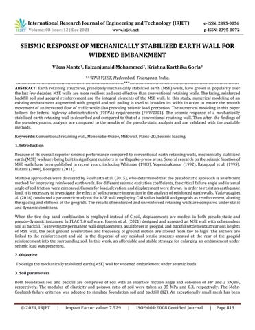
AnMSEwallof6mheightisevaluated,withgeogridaxialstiffnessof2500kN/m,0.6mspacing,andanchorsof4mlengthata 100 inclination. Anchors with a rigidity of 2*105 kN/m and a spacing of 0.5 m are considered in this study. A total of five concretefacingpanelswithalengthof1.2mandawidthof0.2mareinstalledasshowninFig.01.
FacingGeogridpanel H=6m Anchor depthFoundation=2m blockFoundationplate Foundation width=28m
Fig.01 TypicalviewofembankmentmodeledinPlaxis2D Ontopofthe embankment, a surchargeloadof30 kPa isenvisaged basedonthedesignspecificationsgiven byAASHTO (7) The backfill is placed in layers, and the reinforcing and facing pieces are positioned in a sequential order. The approach is continued for each layer until the wall reaches a height of 6 meter. The properties of the facing panels are given it Table 01. Overturning,bearingcapacity,andslidingareallassessedintheMSEwall'sstability.
Plaxis 2D programme includes a two dimensional plane strain model with twelve nodes triangular parts. Clusters are separatedintotrianglecomponentsbythealgorithmduringautomatedmeshconstruction.Priortotheinvestigation,anMSE wallwasdesignedinPlaxis2Dsoftwarethatmetallofthestabilitycheckcriteria. Width=23 m
5. Methodology
Embankment
4. Reinforcement and Facing Panel properties
International Research Journal of Engineering and Technology (IRJET) e ISSN: 2395 0056 Volume: 08 Issue: 12 | Dec 2021 www.irjet.net p ISSN: 2395 0072 © 2021, IRJET | Impact Factor value: 7.529 | ISO 9001:2008 Certified Journal | Page814 usedin thedesign.Theanchorsareconnectedtothegeogridinthe model tocomprehendthegeogrid's increasedtension to thesurroundingrigidsoilthroughanchors.


The Mononobe Okabe (M O) approach is still used by geotechnical engineers to evaluate lateral ground pressures during earthquakes. M O solves the equations of equilibrium using a closed form method and suggests seismic active and passive lateralearthpressures(1)basedonafewfundamentalassumptions.Foranactivewedgeleaningonaretainingwall,theidea achievesglobalforceequilibrium.Thelocationoftheresultantforcemustbeinferredwhenassessingthestabilityofthewall because it is not part of the force equilibrium formulation. The M O formulation is a Coulomb formulation that includes ground acceleration induced pseudostatic inertia force components. Mononobe and Okabe predicted that the total pressure calculatedusingtheirmathematicalmethodwouldoperateonthewallatthesameheightastheinitialstaticpressure,i.e.,H/3 above the base. For practical reasons, the vertical acceleration components of many earthquakes are lower than their horizontalcomponents.Therefore,itlooksreasonabletopresumethattheeffectofverticalcomponentskv maybeconsidered inlessinmagnitude.ThefollowingaretheequationsonwhichM Omethodisbased: 5 10 15 20 25 Time (s)
Fig.02 ShowstheSeismicexciationsof5.4magnitudeearthquake Modeling of the MSE wall in Plaxis 2D by applying an amplitude of 0.1m as shown in Fig.02. After applying the seismic excitations(9),testingforwallstability,determininglateralandverticalforcesonthewall,andlateral walldeformation was carried ThedeformationsandlateralpressuresareexaminedandcomparedtotheMononobe Okabemethod'sresults.
(g)Acceleration
Table 01. Propertiesoffacingpanelsconsideredinthisstudy Properties of Facing panel Magnitude Flexuralrigidity(EI) ⁄ 1.8* Axialstiffness(EA) ⁄ 5.48* Poisson’sratio( ) 0.1 Thickness(D)m 0.2 5.1 Mononobe Okabe Method
International Research Journal of Engineering and Technology (IRJET) e ISSN: 2395 0056 Volume: 08 Issue: 12 | Dec 2021 www.irjet.net p ISSN: 2395 0072 © 2021, IRJET | Impact Factor value: 7.529 | ISO 9001:2008 Certified Journal | Page815
-0.5-1.5-2.5-3-2-100.511.522.5 0
International Research Journal of Engineering and Technology (IRJET) e ISSN: 2395 0056 Volume: 08 Issue: 12 | Dec 2021 www.irjet.net p ISSN: 2395 0072 © 2021, IRJET | Impact Factor value: 7.529 | ISO 9001:2008 Certified Journal | Page816 ( ) ( )( √ ( ) ( ) ( ) ( )) (1) ( ) (2) ( ) (3) ( ) (4) ( ) ( ) (5) ZWhere=zonefactor;I=importancefactor;R=reductionfactor ; ; ; ; ; ; 6. Numerical Modeling
Plaxis 2D software was used to analyze the MSE wall. The existing embankment was built by employing 2 m of granular materialasthefoundationsoiland6mofgranularsoilastheembankmentfill,withatopwidthof14m.Adiaphragmconcrete wallhasbeenusedasafacepanel,aswellasafoundationblocksplate,toincrease(13) thewidthto23m.Hingesintegratethe facingpanels,allowingthemtoreducethemomentduetorotation.Toenhancethesoil'sstiffnessandload carryingprowess, geogrids withanaxial stiffnessof 2500kN/mare positioned0.6mapart along the depth.Anchorswitha lengthof4mand a spacingof0.5marehammeredintotheexistingembankmentata10degree angleandconnected(18)withgeogrids.Thetop oftheembankmentretrievesa30kPasurcharge(11)load,whilethebottomexperiencesaseismicloadduringtheanalysis.
7. Results and Discussion
Thelateralearthpressures,verticalpressures,anddisplacementsarecalculatedatvariousheightsofthewallusingtheabove Mononobe Okabeequationforseismicloads,andtheresultsareplottedinagraphandcomparedtotheresultsobtainedusing thePlaxis2Dsoftware. Undernormalloadingconditionsandwithoutaddinganyreinforcement(i.e.,theconventionalretainingwall),thelateralearth pressureismobilizedatapressureof60.5kN/m2.Similartolateralpressure,verticalpressureisalsomobilizedatapressure of 140 kN/m2. When the conventional wall is modeled as an MSE wall, the stresses mobilize to 21.5 kN/m2 of lateral and verticalpressures,respectively.
International Research Journal of Engineering and Technology (IRJET) e ISSN: 2395 0056 Volume: 08 Issue: 12 | Dec 2021 www.irjet.net p ISSN: 2395 0072 © 2021, IRJET | Impact Factor value: 7.529 | ISO 9001:2008 Certified Journal | Page817 Fig.03 (a) LateralpressuredistributioninConventionalretainingwallandMSEwallundernormalloadingconditons. Fig.03 (b) VerticalpressuredistributioninConventionalretainingwallandMSEwallundernormalloadingconditons. In seismic contingencies, the wall that is modeled in this research indicated reduced lateral stress at the top of the retaining wallascomparedtotheexistingapproachinpreviousstudies,namelytheMononobe Okabemethod,whichisavailableinthe literature. 76543210 0 10 20 30 40 50 60 70 (m)Depth Lateral Pressure (kN/m2) MSE Conventionalwall wall 76543210 0 20 40 60 80 100 120 140 160 (m)Depth Vertical stress (kN/m2) MSE Conventionalwall wal
(m)Depth Lateral
) Mononobe-OkabePlaxis-2D 76543210 0 25 50 75 100 125 150
The stress at the top of the retaining wall is determined to be 18 kN/m2, although the stress obtained using the Mononobe OkabeapproachwasslightlygreaterthanthestressobservedinthisanalysisasshowninFig4(a) Fig.04 (b) VerticalpressuredistributioninConventionalretainingwallandMSEwallunderseismicloadingconditons.
76543210 0 50 100 150 200
Asaresult,itmaybeconcludedthatthisembankmentisstableinthecaseoflateralpressure. Incaseofverticalstresses,the resultsfromFig.04(b)portraythesamescenarioasseeninthecaseoflateralpressure. Asaresult,regardlessoftheapproach usedinthisstudyorthewayaccessibleintheliterature,thestressesmobilizedatthebottomoftheretainingwall. 250 Pressure (kN/m2 (m)Depth Stress (kN/m2)
Vertical
Mononobe-OkabePlaxis-2D
International Research Journal of Engineering and Technology (IRJET) e ISSN: 2395 0056 Volume: 08 Issue: 12 | Dec 2021 www.irjet.net p ISSN: 2395 0072 © 2021, IRJET | Impact Factor value: 7.529 | ISO 9001:2008 Certified Journal | Page818
Fig.04 (a) LateralpressuredistributioninConventionalretainingwallandMSEwallunderseismicloadingconditons.
65432100.00 0.03 0.05 0.08 0.10 0.13 0.15 0.18 0.20 (m)Depth Lateral Displacements (m) LoadingNormal
International Research Journal of Engineering and Technology (IRJET) e ISSN: 2395 0056 Volume: 08 Issue: 12 | Dec 2021 www.irjet.net p ISSN: 2395 0072 © 2021, IRJET | Impact Factor value: 7.529 | ISO 9001:2008 Certified Journal | Page819
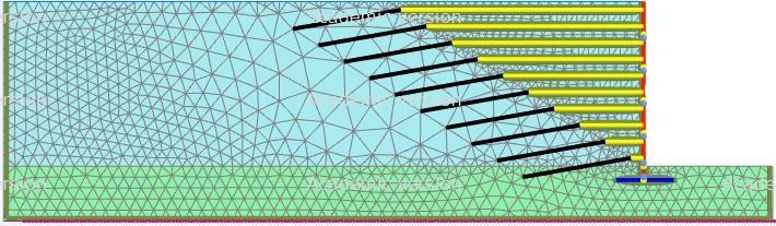
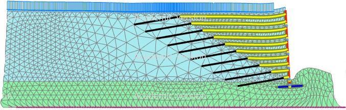
Asallthestressesthatwereobtainedaftermodelingtheexistingembankmentwerelessthanthestressesthatwereobtained from the Mononobe Okabe method, therefore it can be concluded that all the stresses are in the permissible limits. Before finalizingthemodeledretainingwall,thereshouldbeacheckagainstthedisplacementsinthe Fig.06 Typicalviewoflateraldisplacementsbasedondifferentloadingconditions.
8. Conclusions To accommodate the increasing traffic flow, an attempt was made to expand an existing embankment. As a result, the proportions of the embankment and the conventional wall were modeled in Plaxis 2D to meet the traffic requirements. The behavioroftheretainingwallandembankmentundervariousloadingcircumstanceswasinvestigated.Thefollowingfindings weredrawnfromthisresearch: 1. When the retaining wall was strengthened with geogrids and anchors under typical loading conditions, the lateral andverticalearthpressureswereloweredby3and5.5times,respectively.
retainingwall.Fig.(05)andFig.(06) showsthedisplacementsbasedontheloadingconditions.Asthedisplacementswerenot ingreatermagnitude,thereforeitcanbesaidthatthemodeledretainingwallcanbesuggestedtomeettheincreasedflowand requirementsofthetraffic.
Fig.05 Showsthelateraldisplacementsbasedondifferentloadingconditions.
International Research Journal of Engineering and Technology (IRJET) e ISSN: 2395 0056 Volume: 08 Issue: 12 | Dec 2021 www.irjet.net p ISSN: 2395 0072 © 2021, IRJET | Impact Factor value: 7.529 | ISO 9001:2008 Certified Journal | Page820
9. References: 1. Standard,I.(1893).Criteriaforearthquakeresistantdesignofstructures.BureauofIndianStandards,Part,1.
9. Ural, N., & Gergin, A. (2020). Foundation design on problematic soils with high underground water level.Revista de la construcción,19(3),233 245.
12. Suresh Kommu, S. S. (2020). Design of Mechanically Stabilized Earth Wall for Widened Embankment.Solid State Technology,63(5),7911 7918.
4. Karpurapu,R., &Bathurst, R.J.(1995).Behaviour of geosyntheticreinforced soilretaining wallsusing thefinite element method.Computersandgeotechnics,17(3),279 299.
10. Mehta,S.D.,&Shah,S.SeismicAnalysisofReinforcedEarthWallAlongwithSoilStructureInteraction.
7. Standard, A. A. S. H. T. O. (2002). Standard specifications for highway bridges.American Association of Highway and TransportationOfficials,Washington,DC.
13. Saxena,V.P.,&Sikdar,P.K.HIGHWAYCAPACITYSTANDARDININDIA APOLITICALAGENDAPURSUED.
3. Yogendrakumar, M., Bathurst, R. J., & Finn, W. L. (1992). Dynamic response analysis of reinforced soil retaining wall.Journalofgeotechnicalengineering,118(8),1158 1167.
8. Vadavadagi, S. S., Hulagabali, A. M., Solanki, C.H., & Dodagoudar, G. R. SEISMIC ANALYSIS OF MSE WALL USING PSEUDO STATICANDPSEUDODYNAMICAPPROACH.Young,25,25.
2. The earth pressures of the MSE wall were validated and compared with the Mononobe Okabe approach in the instanceofseismicloadingconditions.TheearthpressuresobtainedbytheseismicanalysisinPlaxis 2Dwerelower thanthosedeterminedbyMononobe Okabemethod
14. Joseph, M., & Banerjee, S. (2021, April). Seismic Response of Mechanically Stabilised Earth Retaining Wall. InIOP ConferenceSeries:EarthandEnvironmentalScience(Vol.727,No.1,p.012017).IOPPublishing.
2. Nadim, F., & Whitman, R. V. (1983). Seismically induced movement of retaining walls.Journal of Geotechnical Engineering,109(7),915 931.
3. Sincetheretainingwallandembankmentwerestableattheamountofdisplacements,thedisplacementswereseen tobesmallerunderseismicloadingconditionsaftermodelingtheconventionalretainingwallasMSEwall. There the modeled embankment can be replaced in place of the existing embankment considering all the safety precautions whileplacingthereinforcement,facingpanelsandanchoring.
11. Topolnicki,M.,&Holding,K.(2020).RoadTrafficLoadsforGeotechnicalAnalysesofEmbankments.GroundEngineering, 1 10.
6. Bourgeois, E., Soyez, L., & Le Kouby, A. (2011). Experimental and numerical study of the behavior of a reinforced earth wallsubjectedtoalocalload.ComputersandGeotechnics,38(4),515 525.
5. Hatami, K., & Bathurst, R. J. (2000). Effect of structural design on fundamental frequency of reinforced soil retaining walls.SoilDynamicsandEarthquakeEngineering,19(3),137 157.