
Abstract: A rotavator is used to plough the land by using a series of blades that cuts and pulverizes the soil in a single pass. This work is to present the design and analysis of a rotavator by using CAD software and ANSYS. The CAD software which is used in this study is Solidworks, a 3D modeling design program i.e., mostly used by the operators for its ease of use. During the part of the project, the dimensions of a rotavator are calculated by using design procedures. Using the values obtained from the calculations, a three dimensional model of the rotavator is designed by using Solidworks. Then the 3D model is imported into ANSYS software. By providing required input i.e., force acting on each blade, the static structural and fatigue analysis of the rotavator was performed to get optimum results. The type of rotavator blade used in this present study is an L shaped blade. The type of material used for this L shaped blade is taken from reference i.e., High Carbon Steel. In addition to High Carbon steel, other materials like EN24 Steel, EN8 Steel, Boron Steel, and Chromium Steels were used. From the results, the best material suggested for a new design is boron steel. Finally, the present model is modeled and analyzed to a new design with a change in its radius of curvatures. The new radius of curvatures considered in the modified design is R24, R34, R38, and R40. From the results, it is observed that R38 gives lower deformation and considerably has higher fatigue life. In view of this boron steel with R38 is selected as the best design for the blade. With this new design, the failure of the rotavator blade may be decreased.
3.
4.
5.
6.
INTERNATIONAL RESEARCH JOURNAL OF ENGINEERING AND TECHNOLOGY (IRJET) E ISSN: 2395 0056 VOLUME: 08 ISSUE: 12 | DEC 2021 WWW IRJET NET P ISSN: 2395 0072 © 2021, IRJET | Impact Factor value: 7.529 | ISO 9001:2008 Certified Journal | Page730 DESIGN AND ANALYSIS OF A ROTAVATOR
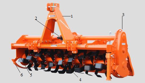
Fig 1. ComponentsofaRotavator
Keywords: Rotavator,Solidworks,ANSYS,Blade,StaticStructuralanalysis,Fatigueanalysis
2.
1.
1. INTRODUCTION Farmmachineryand/orimplementsareanysortofmachineryorimplementsusedintheagriculturalproduction process. This machinery is frequently used for both agricultural and animal production. Farm machinery encompasses a varietyofdevicesrangingincomplexityfromsmallhand heldmachinesusedtocarryoutnumeroustasksrelatedtofields intheproductionofagriculturalproduce.Farmmachineryisfrequentlyutilizedforagriculturalcultivationandharvesting. People utilized tools to produce and harvest food in the past. These farm tools are used to maintain soil loose so that maturecropsmaybeharvested.Thesedevicesaidinthedevelopmentoftinyhandtoolssuchashoes,rakes,trowels,and soon,whicharecommonlyusedingardening.Thenthereisanoutsizedimplementationthatresultedintheenhancement of massive hand tools such as grass shears, gardening toolsets, and so on, and these implements are produced with the goalofgrowingcropsinmind.Arotavatororrotarytillerassemblyconsistsofsubsequentpartswhichareshowninfig.1. Independenttopmast Singleormulti speedgearbox Chain/geardrive Blades Adjustabledepthskids Centralwithoffsetpositions
Bhargavi Alla1* , Dr. B. Madhava Varma2* 1M. Tech. in Mechanical Engineering 2Senior Assistant Professor *MVGR College of Engineering, Vizianagaram, India ***

Singha et al. [8] used the design of experiments to investigate the influence of hard faced Cr alloy on abrasive wear of low carbon rotavator blades. They investigated using hard facing as a surface modification approach and a Cr basedelectrodeinthisresearch.Arotavatorblademadeofhightensilelowcarbon(0.3)steelisemployedfortheir job.An experimentisusedtoinvestigatetheinfluenceofchromiumalloyonthebasematerial.Thesurfacehardnessofbladesis raisedoncechromiumisadded.ThewearresistanceofbladesisdeterminedusingtheASTMG 99standardweartesting method. The hard faced blades have a stronger wear resistance than conventional rotavator blades, according to the resultsofthis Mishrastudy.etal.
Ravindraetal.[4]investigatedhowtoimprovethecurrentdesignoftheL shapedrotavatorblade.Thetwoblade materials discussed in this study are EN 8 steel and EN 24 steel. In order to increase the strength and weed removal efficiency, the blade shape was changed and structural analysis was undertaken on both the present blade and the modifiedblade.Highchromiumsteel,H13steel,andD3steelarealloptionsforbladematerial.Themodificationsmadeto thecurrentdesignyieldedthegreatestresultswiththeleastamountofstressanddistortion.
Tewari et al. [3] explained the design of a tractor PTO operated rotavator. The design of a rotavator for a 30 hp tractoriscalculatedbyusingdesignprocedures.Inthispresentwork,theforceactingoneachbladeiscalculatedbyusing aspecificworkmethod.Theforceexertedoneachbladeisdeterminedtobe1064.1N,andthebladethicknessandcutting widtharedeterminedtobe5mmand30mm,respectively.
A rotavator is a type of agricultural tillage device that is often regarded as the most essential secondary productionandlandproductivitytool.Itisoneofthetypesofequipmentusedbyfarmerstoimproveseedbedpreparation. Furthermore,thisrotavatorhasseventimesthemixingcapacityofaplough[1,2].Therotavatorispoweredbyatractor drivenPower Take off(P.T.O)shaftwith a tractor powerof30hp,and theshapeandmaterial of the bladeare L shaped blades of High Carbon steel [3]. The design of a rotary tiller with an L shaped blade is optimized by decreasing weight, cost,andenhancingfieldperformancetoachievehighweedremoval effectiveness[4].Ingeneral,rotavatorsoperatewell in all acceptable soil conditions but require a lot of energy, but rotary tilling saves more labor than conventional tillage methodsRotavators[5]. are increasingly being employed in agricultural applications because of their simple design and high efficiency. Using this rotavator, primary and secondary tillage operations may be combined in a single stage [6]. Despite theirhighenergyconsumption,rotarytillershavetheabilitytoprovideawiderangeoftillageapplicationsinasinglestep, thustheoverallpowerrequiredforthesemachinesisminimal[7].
[9] investigated the several causes of rotavator failure. The existing rotavator is analyzed by doing modeling and carrying out ANSYS analysis. EN19 was utilized for the rotavator shaft, SAE 1020 for the flange, and AISI 5140 for the bolts. They discovered that the flange material is insufficient to sustain the various sorts of forces that are appliedtoit.Asaresult,theyproposedEN19asnewmaterial(oilQuenched&drawn).
Kajaleetal.[1]studiedtheoptimizationofrotarytillagetoolcomponentdesignandCAEanalysis Theyconducted a structural analysis of a rotavator utilizing CAD software and the finite element technique and simulation method. CAD softwareisusedtomodel thenumerous tillagetoolpartsofa tiller.Thissoftware wasgivenall oftheinputsfora 35hp and 45 hp tractor, as well as the boundary conditions. This research identifies a suitable tolerance for changing the proportions of rotavatorframesectionsand sidegearboxes to minimize excessive weightina solid section whileraising thebladeweightforreliablestrength.Afterdemonstratingitspracticalresultsfromfieldperformance,thecurrentmodel with a tillage blade is subjected to new design constraints with a shape adjustment for optimal weed removal effectiveness.Vegadetal.[2]investigatedthreetypesofrotavatorbladesusingSolidworksandANSYSsoftware(i.e.C,Hatchet, andL shapedblade).Solidworksisbeingusedtooptimizethedesignofthreedifferenttypesofblades.Highcarbonsteelis employed as the blade material. The optimized design of a blade indicates that stress, deformation, and mass was decreased when compared to the initial design, and that the hatchet shaped blade is more likely to break under operationalconditionsthantheC shapedblade.
Selvietal.[10]conductedanexperimenttodevelopa newgeometrical model forbettersoiltillage.Thebladeis made up of three separate materials: stainless steel, mild steel, and structural steel, which are all developed using computersoftware.Usingthesethreematerials,staticanalysiswasperformed,andanewmaterialthatisbetterthanthat materialwascreated,followedbythenextstepintheprocess.Themajorgoalofthisnewdesignistosavetimeandmoney by reducing labor expenses and reducing the amount of material used. Here, a new material with excellent mechanical strengthischosen.
INTERNATIONAL RESEARCH JOURNAL OF ENGINEERING AND TECHNOLOGY (IRJET) E ISSN: 2395 0056 VOLUME: 08 ISSUE: 12 | DEC 2021 WWW IRJET NET P ISSN: 2395 0072 © 2021, IRJET | Impact Factor value: 7.529 | ISO 9001:2008 Certified Journal | Page731
2. LITERATURE REVIEW
Power available at the P.T.O. Shaft: BrakehorsePoweroftractor = 30hp SothepoweravailableatP.T.O.shaft == 26.1hp Assume20%lossofpowerthroughtransmission,poweravailableattherotavatorshaftis Power,P == 20.88hp = 15.57648kw Therefore,poweravailableattheP.T.O.shaft,P = 15.6kw RPM of Rotor: Letusconsiderforwardspeedoftractor,v = 3km/h = 0.834m/s Letustakevelocityratio,λ = =5 (itcanvarybetween2.5to5)
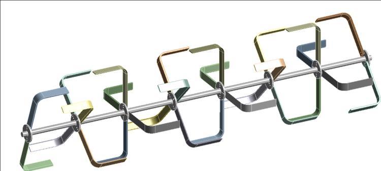
Thedesigning process ofa rotavatorisdoneinoneofthe CADSoftwarethatis Solidworks Afterthe designof a rotavator, the required model is imported into the ANSYS software for the analysis part. Static structural analysis and fatigue analysis are the types of analysis used in this work. In order to do a fatigue analysis, the foremost work is to completethestructuralanalysis,becausethestressvaluesareneededfortheoperationoffatigueanalysis.TheL shaped rotavatorbladeissubjectedtoatangentialforce. Thestaticstructuralanalysisisdonetocheckthereactionofloadslike Von MisesstressandTotal deformation.Thedesignofthe rotavatorisconsideredsafeonlywhenthemaximumstresses inducedinthebladematerialshouldnotexceedtheyieldstrengthoftheactualmaterial Inordertogetaccurateresults,theassemblydesignoftherotavatorbladeandrotavatorshaftisbeendone.
INTERNATIONAL RESEARCH JOURNAL OF ENGINEERING AND TECHNOLOGY (IRJET) E ISSN: 2395 0056 VOLUME: 08 ISSUE: 12 | DEC 2021 WWW IRJET NET P ISSN: 2395 0072 © 2021, IRJET | Impact Factor value: 7.529 | ISO 9001:2008 Certified Journal | Page732
Fig-2. DesignofaRotavator
3. METHODOLOGY
From the study of all the above papers, it is observed that most of the blades of the rotavator bends and breaks whilecultivation.Thisisbecausetheexistingdesignsarenotabletowithstandthefluctuatingloadconditionsinthefields. Due to that, the life of the blades will reduce, and hence it may not be convenient for the farmers to use them. So it is requiredtodesignabladethatwithstandshigherfluctuatingloadconditionswithlongerlife.
4. DESIGN CALCULATIONS OF A ROTAVATOR Inthispresentstudy,wehavedesignedarotavatorfora30hptractor.Thedesignofa rotarytillerbladedepends on the type of blade, no. of blades, and the arrangement of the blade. In order to design the rotavator, specific work becomesthebasisforthedesign[3].Itdefineshowmuchvolumeofthesoil,thebladeswillbehandling.Afterthatonlywe canthinkofthepowersource.
INTERNATIONAL RESEARCH JOURNAL OF ENGINEERING AND TECHNOLOGY (IRJET) E ISSN: 2395 0056 VOLUME: 08 ISSUE: 12 | DEC 2021 WWW IRJET NET P ISSN: 2395 0072 © 2021, IRJET | Impact Factor value: 7.529 | ISO 9001:2008 Certified Journal | Page733 Where,u=Rotorspeed,m/s v=forwardortractorspeed,m/s = 5 = 5 Therefore,rotorspeed, u = 4.17m/s Rotorspeed, u = Where,R=radiusofrotor=25cm 4.17 = N = 159.28 Therefore,RPMofrotor, N = 160RPM Peripheral force acting on a constant arm: Power = force velocity P = Where,k0 =peripheralforce,N 15.6 103 = k0 = 3724.225668N Specific work of a rotavator: A = A0 +AB Where,A0=Staticspecificwork=0.1C0k0,kgm/cu.Decim AB=Dynamicspecificwork=0.001αuu2or0.001αvv2,kgm/cu.Decim C0=Coefficientrelativetothesoiltype=2.5to5,takeC0=3 K0=Specificstrengthofsoil,kg/cu.Decim αv &αu=Dynamicalcoefficients,kgs2/m4 A0 = C0 ki = 3 0.15 = 0.45kg/cm2 AB = α u2 = 500 (4.17)2 = 8694.45kg/m2 = 0.869445kg/cm2 SpecificWork,A= A0+AB
INTERNATIONAL RESEARCH JOURNAL OF ENGINEERING AND TECHNOLOGY (IRJET) E ISSN: 2395 0056 VOLUME: 08 ISSUE: 12 | DEC 2021 WWW IRJET NET P ISSN: 2395 0072 © 2021, IRJET | Impact Factor value: 7.529 | ISO 9001:2008 Certified Journal | Page734 = 0.45+0.869445 = 1.319445kg/cm2 Moment acting: M = Where,a=depthofoperation=10cm A=SpecificWork,kg/cm2 Z=No.ofbladesinoneplane L=Bitelength= bm=Widthofthemachine,cm M === M = 65.97225bm Where,M = k0 R M = 3724.225668 25 = 93105.6417Ncm = 9490.891101kgcm 65.9225bm = 9490.891101 bm = 143.970 = 144cm Number of flanges on rotavator shaft: nf = nf == 7.2 Thereforethenumberofflanges,nf = 8 Number of Blades: nb = (2 2)+(6 4) = 28 Note:Eachflangeconsistsof4bladesbuttheoutermostrotoronbothendsconsistsof2bladesoneach.
INTERNATIONAL RESEARCH JOURNAL OF ENGINEERING AND TECHNOLOGY (IRJET) E ISSN: 2395 0056 VOLUME: 08 ISSUE: 12 | DEC 2021 WWW IRJET NET P ISSN: 2395 0072 © 2021, IRJET | Impact Factor value: 7.529 | ISO 9001:2008 Certified Journal | Page735 Arrangement of the blades on the flanges at an angular interval: A0 == 12.8571420 Force acting on one blade: k0 = 3724.225668N = 379.635644kg Assumingone fourthofthebladewillstrikeonthesoilsurface, Force,k0 = ⁄ = 54.23366343kg Consideringthefactorofsafetyas2,theforceactingononebladeisgivenas k0 = 54.23366343 2 = 108.467kgf = 1064.06N Moment acting on blade: M = k0 R = 1064.06 0.25 = 266.016Nm Bending stress: �� = Where,M=Momentactingonblade=k0 R I=Momentofinertia =bh3/12 Y=h/2 h=widthoftheblade b=thicknessoftheblade �� = ( ⁄ ) ⁄ = ( ⁄ ) ⁄ == Therefore,�� =
INTERNATIONAL RESEARCH JOURNAL OF ENGINEERING AND TECHNOLOGY (IRJET) E ISSN: 2395 0056 VOLUME: 08 ISSUE: 12 | DEC 2021 WWW IRJET NET P ISSN: 2395 0072 © 2021, IRJET | Impact Factor value: 7.529 | ISO 9001:2008 Certified Journal | Page736 Torsional Stress: == ( ) = Maximum Shear Stress: �� = √ �� = √( ) ( ) Hereshearstressofhighcarbonsteelhasbeentakenas1080kg/cm2 1080 = √ h3 = h3 = 20.02118985 h = 2.7153cm h = 3cm Therefore, b = h/6 b = 3/6 b = 0.5cm Rotavator shaft design: �� = ConsideringyieldStressofhighcarbonsteelas525MPa �� === 262.5N/mm2 262.5 = d3 = d3 = 7741.765543 d = 17.2815 Therefore,thediameteroftherotavatorshaft,d = 20mm.
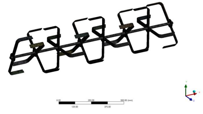
INTERNATIONAL RESEARCH JOURNAL OF ENGINEERING AND TECHNOLOGY (IRJET) E ISSN: 2395 0056 VOLUME: 08 ISSUE: 12 | DEC 2021 WWW IRJET NET P ISSN: 2395 0072 © 2021, IRJET | Impact Factor value: 7.529 | ISO 9001:2008 Certified Journal | Page737 Table 1. Specificationsofanexistingdesignedrotavator S.No Notations Parameters Units Dimensions 1 Workingdepthofarotavator a mm 100 2 Workingwidthofarotavator b mm 1440 3 Rotorrpm N RPM 160 4 Forwardspeedoftractor v m/s 0.834 5 Rotorspeedoftractor u m/s 4.17 6 Poweroftractor P Hp 30 7 Verticallengthofblade Lv mm 170 8 Horizontallengthofblade Lh mm 130 9 Bladecuttingwidth h mm 30 10 Thicknessofblade b mm 5 11 Radiusofcurvature R mm 28 12 Bladeangle �� degree 90 13 Chamferofblade CH mm 5*450 14 Totalno.ofblades nb 28 15 Totalnumberofflanges nf 8 16 No.ofbladesoneachflange z 4 17 Forceactingonconstantarm k0 N 3724.225 18 Specificworkdonebyarotavator A Kg/cm2 1.319445 19 Diameterofrotavatorshaft d mm 20 20 Forceactingoneachblade k0 N 1064.1 Materials Materials used in the production of rotavator blades should have mechanical features such as high wear resistance,compressivestrength,density,andbecheaplyaccessible.Theotherfourmaterials,inadditiontoHighCarbon steel,havebeenchosenforthisexperiment. Table-2. MaterialPropertiesofrotavatorblade MaterialName Yield Stress (MPa) RatioPoisson (kg/mDensity 3) Elastic (N/mmModulus 2) HighCarbonSteel 525 0.29 7480 1.97e5 EN24Steel 850 0.3 7840 2.10e5 EN8Steel 850 0.3 7850 2.05e5 BoronSteel 1350 0.3 7880 2.03e5 ChromiumSteel 700 0.29 7700 2.05e5 5. ANALYSIS OneofthemostcommonlyusedsoftwareforanalysispurposesisANSYSsoftwarebecausetheresultsobtainedby ANSYS are close to accurate values. We can perform a different kind of engineering problems in ANSYS software. The different types of analysis we can perform are Static Structural Analysis, Steady State Thermal Analysis, Transient Structural,TransientThermal,Modal,Harmonic,Buckling,Fatigue,ComputationalFluidDynamics,etc.themodelingofthe rotavator is done using CAD software that is Solidworks. A rotavator is designed by taking the dimensions obtained in designcalculations.AStaticStructural Analysis and fatigue analysis are done with calculated loading conditions. The material propertiesaretobechangedinthemateriallibrarysectioninANSYS.Wecancreateanewmaterialifitisnotavailablein thelibraryorcanedittheexistingmaterial'sproperties.ThenthemodelisimportedintoANSYSworkbenchas.stpformat usinggeometrytabinANSYSstandalonesystem.Wewillgenerateameshafterloadingthemodelintotheprogrameand specifyingthemeshsize.Themodelwillnextbesubjectedtoboundaryconditions.
Fig 3. Meshofarotavator
INTERNATIONAL RESEARCH JOURNAL OF ENGINEERING AND TECHNOLOGY (IRJET) E ISSN: 2395 0056 VOLUME: 08 ISSUE: 12 | DEC 2021 WWW IRJET NET P ISSN: 2395 0072 © 2021, IRJET | Impact Factor value: 7.529 | ISO 9001:2008 Certified Journal | Page738
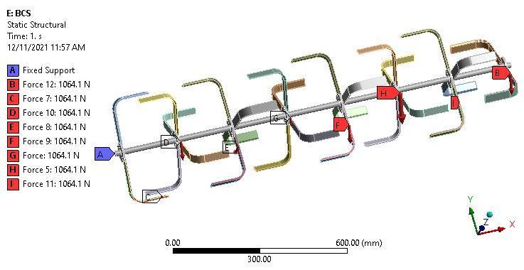
After meshing the boundary conditions have to be given. Those conditions are forces acting on each blade as 1064.1Nfortherespectivedesignandmodelasthevaluesobtainedfromthecalculation. RESULTS & DISCUSSION
6.
Fig 4. Boundaryconditionsofarotavator
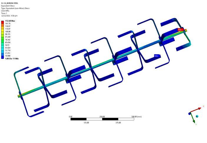
Fig 5. Equivalent(von mises)stress Fig 6. Totaldeformation Fig 7. FatigueLife
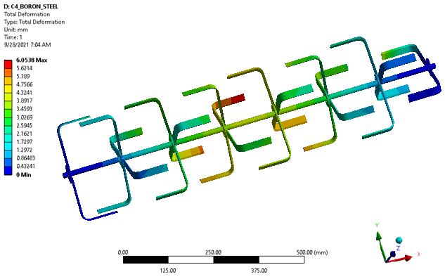
Thebelowfiguresaretheresultsofequivalent(von mises)stress,deformation,andfatiguelifeofarotavatorblademade of Boron Steel. The equivalent (von mises) stress, total deformation, and fatigue life results of rotavator blade made of otherdifferentmaterialssuchasEN24steel,EN8Steel,andChromiumSteelarefoundtobe181.74,170.38,169.65MPa, 6.798,6.3839,6.4494mmand49525,50373,51155cycles.
Withtheseinputs,wecangeneratethesolutionforequivalent(von mises)stress,deformation,andfatiguelife.In the solution tab, we insert the Equivalent (Von Mises) stress, total deformation, fatigue life and we click on Solve. The below figures are the results of equivalent (von mises) stress, deformation, and fatigue life of a rotavator blade made of HighCarbonSteel.
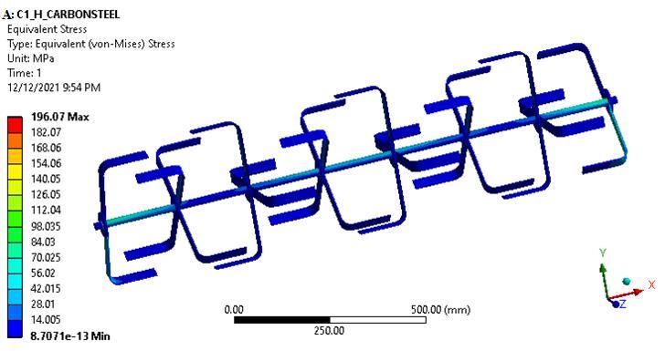
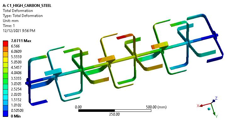
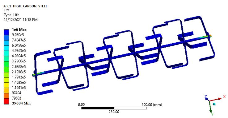
INTERNATIONAL RESEARCH JOURNAL OF ENGINEERING AND TECHNOLOGY (IRJET) E ISSN: 2395 0056 VOLUME: 08 ISSUE: 12 | DEC 2021 WWW IRJET NET P ISSN: 2395 0072 © 2021, IRJET | Impact Factor value: 7.529 | ISO 9001:2008 Certified Journal | Page739 Fig 8 Equivalent(von mises)stress Fig 9 TotalDeformation Fig 10 FatigueLife Fromtheresults,thebestmaterialfromtheexistingdesignisfoundasboronsteel withEquivalent(von mises)stressas 152.68MPa,Totaldeformationas6.0538mm,andfatiguelifeas64994cycles. Table-3. Resultsofexistingdesignofarotavator Material Name Stress(vonEquivalentmises)(MPa) (mm)Deformation Fatigue (cycles)Life HighCarbonSteel 196.07 7.0711 39604 EN24Steel 181.74 6.798 49525 EN8Steel 170.38 6.3839 50373 BoronSteel 152.68 6.0538 64994 ChromiumSteel 169.65 6.4494 51155 It is also studied that the effect of radius of curvature on blade strength. The rotavator blade is modeled and analyzedbyconsideringdifferent radiusofcurvatures suchasR24,R34,R38,andR40. UsingANSYSsoftwarethemodel has analyzed the results like equivalent (von mises) stress, deformation, and fatigue life for the different radius of curvaturesthatareshownbelow.

7. CONCLUSION Thisresearchfocusesonthedesignandanalysisofarotavatorbyconsideringthebladeas anL shapedrotavator blade.Fromtheresearch,weobservedthattherotavator bladeisusuallymanufacturedfromHighCarbonSteelandmild steel, whereas in our study in addition to High Carbon Steel the four different materials such as EN24 Steel, EN8 Steel, BoronSteel,andChromiumSteelareused.Thesematerialshavedifferent propertiesandtheyaresimulatedinANSYSfor
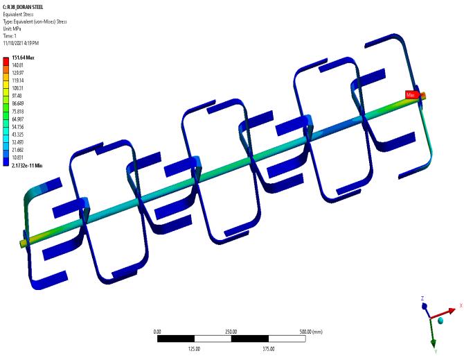
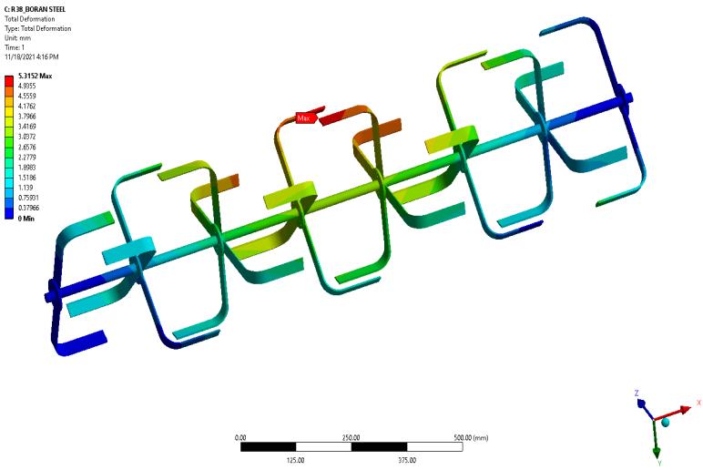
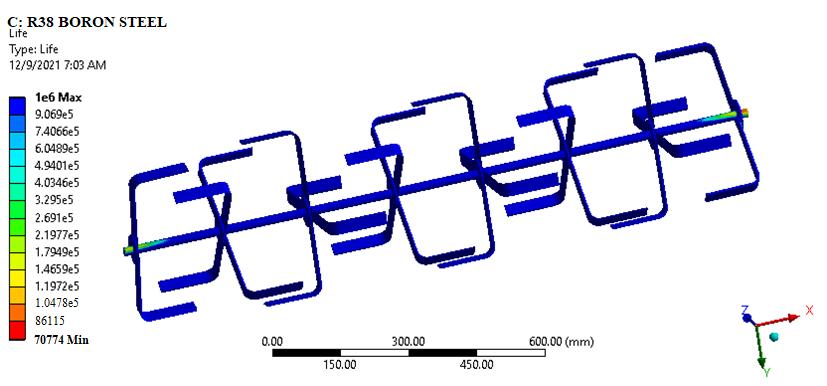
Table 4. Resultsofmodifieddesignofarotavator Radius of Curvature Equivalent (von mises) Stress (MPa) (mm)Deformation Fatigue (cycles)Life R24 15506 6.9682 65212 R28 152.68 6.0538 64994 R34 151.79 6.2906 70513 R38 151.64 5.3152 70774 R40 151.55 6.9733 70914 Bycomparingalltheobtainedresults,thebestdesignofarotavatorbladeisfoundasR38withminimumdeformationof 5.3152mmandconsiderablyhasalongerfatiguelifeof70774cycles.
INTERNATIONAL RESEARCH JOURNAL OF ENGINEERING AND TECHNOLOGY (IRJET) E ISSN: 2395 0056 VOLUME: 08 ISSUE: 12 | DEC 2021 WWW IRJET NET P ISSN: 2395 0072 © 2021, IRJET | Impact Factor value: 7.529 | ISO 9001:2008 Certified Journal | Page740 Fig-11 Equivalent(von mises)stress Fig-12 TotalDeformation Fig 13 FatigueLife
The boron steel blades of varying radii are modeled and analyzed to get the optimum results. From the results, it is observedthatthevaluesofequivalent(von mises)stress,deformation,andfatiguelifeofR24,R34,R38,andR40radiusof curvaturesarefoundtobestressvaluesas15506MPa,151.79MPa,151.64MPa,and151.55MPa,deformationvaluesas 6.9682mm, 6.2908 mm, 5.3152 mm, and 6.9733 mm, fatigue life values as 65212, 70513, 70774, and 70914 cycles. ComparingtheresultsoftheR28radiusofcurvaturewiththeotherfourdifferentradiiofcurvaturesisasshownbelow.
INTERNATIONAL RESEARCH JOURNAL OF ENGINEERING AND TECHNOLOGY (IRJET) E ISSN: 2395 0056 VOLUME: 08 ISSUE: 12 | DEC 2021 WWW IRJET NET P ISSN: 2395 0072 © 2021, IRJET | Impact Factor value: 7.529 | ISO 9001:2008 Certified Journal | Page741 staticstructuralanalysisandfatigueanalysis.Thusthestaticstructuralanalysisandfatigueanalysisgivesadetailedstudy about those five materials such as equivalent (von mises) Stress, deformation, and fatigue life. Out of different blade materials, it is observed that boron steel is best in view of lower deformation with 6.0538 mm and higher fatigue life of 64994cycles.Soboronsteelisselectedasthebestmaterialforthefurtherprocess. Toseetheeffectofcurvatureradius, different radii are taken for boron steel blades such as R24, R34, R38, and R40. By considering the above radius of curvaturestherotavatorismodeledandanalyzedfortheresultslikestress,deformation,andfatiguelife Fromtheresults, it is observed that R38 is the best radius of curvature in view of lower deformation 5.3152 mm and also has a higher fatigue life of 70774 cycles. It is concluded that the best blade design for a rotavator blade is boron steel with an R38 radiusofcurvatureinviewofalowerdeformationandconsiderablyhaslongerfatiguelife.
[16] U.S.Kankal,D.S.KaraleS.H.Thakare&V.P.Khamballkar.PerformanceEvaluationofTractorOperated Rotavatorin DrylandandWetlandFieldConditions:InternationalJournalofAgriculturalScienceandResearch(IJASR)ISSN(P): 2250 0057;ISSN(E):2321 0087Vol.6,Issue1,Feb2016,137 146
[4] Mr. Ravindra B. Kankal and Prof. K. R. Sontakke. “Design and Analysis of L Shape Rotavator Blade”, International JournalofAdvancedResearchinScience,CommunicationandTechnology(IJARSCT)Volume1,Issue1,January2020.
[3] Lecture6:DesignofatractorPTOoperatedrotavator,Prof.V.K.Tewari,IITKharagpur,July2018.
[5] R.G.Jakasania.StructuralAnalysisofHatchetTypeRotavatorBladeinCADSoftware:NationalConferenceonRecent trendsinEngineering,Management,Pharmacy,ArchitectureandScience,‘NCETEMPAS 2016’.
REFERENCES
[7] Culpin,C.(1981),FarmMachinery.10thedn,GranadaTechnicalBooksPress,Spain.
[10] Dr.SelviK.C.Anewbladedesignofrotarytillerandstaticanalysisusingcomputeraidedtool:Researchgate.Vol.53, pp.30 34,jan2017.
[11] M.A.Matin,J.M.Fielke,J.M.A.Desbiolles.Torqueandenergycharacteristicsforstrip tillagecultivationwhencutting furrowsusingthreedesignsofrotaryblade:ScienceDirect,Bio systemsEngineering129(2015)329 340.
[14] MalchiChengaiah,GanapathiAshok.Less CostRotavatorDesignForCultivation: International Journal ofInnovative TechnologyandResearchvolumeNo.4,IssueNo.6,October November2016,5097 5099.2320 5547.
[15] G.SrikanthReddy,J.Narsaiah,G.Shashikala.DynamicAnalysisonTillageEquipmentUsedinAgricultureUsingAnsys Software:©2017IJSRST|Volume3|Issue7|PrintISSN:2395 6011|OnlineISSN:2395 602X
[13] Subrata Kumar Mandal† , Basudeb Bhattacharyya. Design Optimization of Rotary Tiller Blade using Specific Energy Requirement:InternationalJournalofCurrentEngineeringandTechnology,E ISSN2277 4106,P ISSN2347 516, 24July2016,Vol.6,No.4
[9] Mr. S. A. Mishra, Dr . A. R. Sahu. Computer Aided Design and Analysis of Rotor shaft of Rotavator: International EngineeringJournalforResearch&Development,Vol.3Issue2,E ISSNNO: 2349 0721.
[8] Sukhraj Singha, Jonny Garga. Effect of hard faced Cr alloy on abrasive wear of low carbon rotavator blades using design of experiments: Science Direct, International Conference of Materials Processing and Characterization. MaterialsToday:Proceedings5(2018)3390 3395.
[2] Er. G. M. Vegad, R. Yadav. Design Analysis and Optimization of Rotary Tiller Blades Using Computer Software: AgriculturalmechanizationinAsia,AfricaandLatinAmerica2018VOL.49NO.1.
[12] B. vivek, E. Deeparaj, K. Karthick. Fabrication and performance analysis of rotavator blades for its enhancement: IJRET.vol.6,pp.1 5,jan2018.
[1] Shinde, G. U., S. R. Kajale and J. M. Potekar. 2011. Computer aided engineering analysis and design optimization of rotarytillagetoolcomponents.InternationalJournalofAgriculturalandBiologicalEngineering,4(3):1 6.
[6] Topakci, M., Celik, H. K. and Yilmaz, D. (2008), Stress analysis on transmission gears of a rotary tiller using finite elementmethod.AkendizÜnivresitesiZiraatFakultesiDergisi.21(2):155 160.
[18] V.M.Salokhe,M.HanifMiahandMakotoHokit.EffectofBladetypeonpowerrequirementandPuddlingqualityofa rotavatorinwetclaysoil:JournalofTerramechanics,Vol.30,No.5,pp.337 350,1993.
INTERNATIONAL RESEARCH JOURNAL OF ENGINEERING AND TECHNOLOGY (IRJET) E ISSN: 2395 0056 VOLUME: 08 ISSUE: 12 | DEC 2021 WWW IRJET NET P ISSN: 2395 0072 © 2021, IRJET | Impact Factor value: 7.529 | ISO 9001:2008 Certified Journal | Page742 [17] D. Ramesh Kumar and P. Mohanraj. Design and Analysis of Rotavator Blades for its Enhanced Performance in Tractors:AsianJournalofAppliedScienceandTechnology(AJAST)Volume1,Issue1,2017
[19] H. Bernacki, J. Hanan, and Cz. Kanafojski, “Agricultural Machines Theory and Construction,” U.S. Department of Commerce,vol1,SpringField,1972.
[20] Mahal, J. S., Manes, G. S., Apoorv, P., Singh, M. and Dixit, A. (2012), Study on Blade Characteristics of Commercially AvailableRotavatorsinPunjab,AgriculturalEngineeringToday36(3):8 11.