***
2. LITERATURE REVIEW
1PG Scholar, Department of Engineering Design, Government college of Technology, Coimbatore.
International Research Journal of Engineering and Technology (IRJET) e ISSN: 2395 0056 Volume: 08 Issue: 12 | Dec 2021 www.irjet.net p ISSN: 2395 0072 © 2021, IRJET | Impact Factor value: 7.529 | ISO 9001:2008 Certified Journal | Page724
[4] Investigations on the premature failure of suspension helical spring of a passenger car, which failed during the service within few months and identified the reasonsforthefailure.Theresultsstatedthattheinherent material defectinassociationwithdeficient processingled tothefailureofthespring.
Investigation of Helical Spring by Varying Loads and Cross Sections
[1] Investigations with the pioneering works that the boundaryelementmethodusedtoapplytheoryofelasticity and to develop an approximate result to satisfy governing equationsand boundaryconditions along thesurface ofthe helical[2] Design and optimization of helical springs with a circular and a triangular profile was studied and from analysis, the circular profile has a lesser total deformation and a lesser equivalent maximum strain compared to triangularprofile.
Abstract When a spring is stretched or twisted by an external force, strain energy is stored in the spring, which is then released when the external force is withdrawn. The most significant component of a vehicle suspension is the compression spring system, which is designed to halt shock impulses. Suspension systems employ the compression and expansion cycle transformation concept. In motorbikes, suspension systems are used to increase handling, braking performance, safety, and comfort by separating passengers from road noise, bumps, and vibration. The purpose of the shock absorber is to absorb or disperse energy. Because of the greatly reduced amplitude of disturbances, it reduces the effect of driving over rough terrain in a vehicle, resulting in improved ride quality and better comfort. When a spring breaks, an examination is required to assess the material quality utilised in the manufacture of any functioning equipment or a functional model. The best material for the job can be selected based on availability, quality, price, and compatibility with working methods. At the moment, manufacturing industry spring design engineers prefer to employ this approach over a real one. A suspension system is constructed in CATIA V5R19 and studied in ANSYS 17.2 with various material characteristics in this work.
Teddy Jefri1 , NandaKumar2
[3] Deflection induced in chrome silicon spring is very much less than deflection induced in hard drawn carbon spring So, Chrome silicon spring steel is the optimum suitable material with low weight and high stiffness for helical spring application like mono shock suspensions in bikesandmanymore.
[5] Helical springs subjected to axial load under different dynamic conditions. The mechanical system, composedofa helical springandtwoblocks,isconsidered and analyzed. Multi body system dynamics theory is appliedtomodel thesystem,wherethespringismodelled by Euler Bernoulli curved beam elements based on an absolutenodalcoordinateformulation
2Professor, Department of Engineering Design, Government college of Technology, Coimbatore.
1. INTRODUCTION Coilspringsareabasicflexiblemechanicalelement usedin many industrial applications such as balancers, brakes, vehiclesuspensionsandenginevalvestoperformfunctions such as applying force, storing or energy absorption, flexibilityofmechanicalsystems andmaintaining forceor pressure.In addition, for the most popular forms of vibration absorbers, helical springs act as the elastic element. Non circular springs for lateral space limits and circular helical springs with a non prismatic shape for vertical space constraints can be used to prevent this. The most prevalent non circular helical springs seen in light firearms are rectangular helical springs. Spring deflection under axial load and maximum stresses induced are two importantfactorstoconsiderwhendesigningandselecting springsforpracticalapplications. Oneofthekeyfocusesof helicalspringresearchisstressanalysis.HardDrawnWire, Phosphorus Bronze, Spring Brass, Oil Tempered Wire, Chrome Silicon, and Stainless Steel are some of the most prevalentspringmaterials.
[6] Methodology Presented for designing prismatic springs of non circular helical shape and non prismatic springs of circular helical shape using analytical and numerical methods using CAD and FEM. It is found that working on modelling and analysis of different types of helical springs with variable cross sections in research works using different available software from past to present.
Key Words: Helical Spring, Low Carbon Steel, Chromium Vanadium Steel, Square, Elliptical, Circular.

Step 5:Selecttheriboptionfromthesketch basedtool barandribalongtheprofilebyclickingontheExitapp. Draw ends supports with the sketch based tool bar and theprofiletoolbar.
Repeat the above steps and change the cross section as SQUAREandELLIPSE.
Selection of Software Material Selection Varying the Loads Modelling for Various Cross Section Structural Analysis through ANSYS Results and DiscussionDiscussion
Step 4: Draw the circular cross section on a plane perpendiculartothehelixprofile.
:
Table 1 AnalyzedMaterialProperties materials for helical this study. Low carbon structuralsteelandchromiumvanadiumsteel Spring using CATIA V5 FORCIRCULARCROSSSECTION
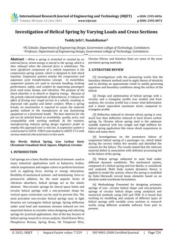
Fig 1:Ellipticalcrosssectionhelicalspring Fig 2:Squarecrosssectionhelicalspring
wereused asthematerials. 4.1 Modelling of
Modeling and analysis of several
Step 1: Select Part Design from the Mechanical Design menu.ClickonthedrawingandselecttheXYplane.
Step 2: From the profile tool bar, select the point and moveittoadistanceof(50,0)fromtherelevantaxis.
Step 3: Select the helix tool from the Exit app and designthehelixprofilewiththeappropriatedimensions.
springs were carried out in
International Research Journal of Engineering and Technology (IRJET) e ISSN: 2395 0056 Volume: 08 Issue: 12 | Dec 2021 www.irjet.net p ISSN: 2395 0072 © 2021, IRJET | Impact Factor value: 7.529 | ISO 9001:2008 Certified Journal | Page725 3. METHODOLOGY 4. MATERIAL PROPERTIES AND SPECIFICATION OF THE SPRING Accordingtothedirectionandtypeoftheforceexertedby the spring when it is deflected, helical springs are classed ashelicalcompressionspringsorhelicalextensionsprings. Thehelicalcompressionspringiscoveredinthissection. For Low Carbon Structural Steel (LCS) Young’sDensity=Poissonmodulus=1.98e5MPa,ratio=0.3,7700kg/m 3 For Chromium Vanadium Steel (CVS) Young’smodulus=2.07e5MPa, Poissonratio=0.3, Density=7860kg/m3
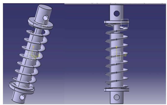
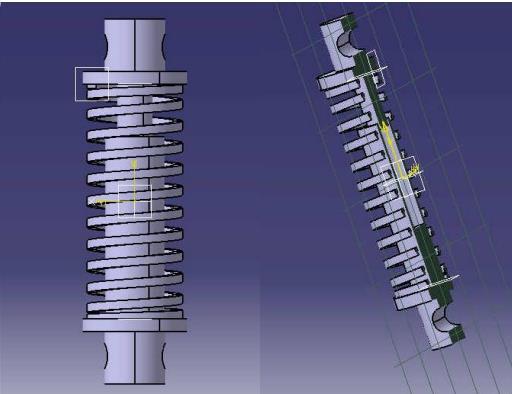


Fig -5.3: LCSspringwithloadof2750N (EquivalentElasticStrain)
Fig 5.4: LCSspringwithloadof2750N (EquivalentVonMisesStress)
ANSYS 17.2 is used for pre and post processing of the staticanalysisofconventionalhelicalcoilsprings.Typesof mesh, mesh size, spring seat types, and spring end connectiontypesareallconsidered. Tobegin,thespringis meshedwithvariousmeshkindsandsizes,andtheresults are compared. Finally, the various forms of spring end connections are investigated, and an analytical model is developed based onall ofthese factors.Total deformation, equivalentelasticstrain,equivalentvonMisesstress,shear strain, and elastic shear stress of the coil spring according to applied force are selected and their convergences trackedduringtheanalyticalprocess.
Fig 5.5: LCSspringwithloadof2750N(ShearStress)
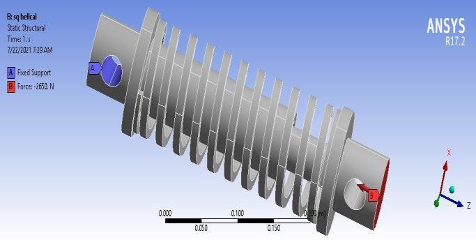
International Research Journal of Engineering and Technology (IRJET) e ISSN: 2395 0056 Volume: 08 Issue: 12 | Dec 2021 www.irjet.net p ISSN: 2395 0072 © 2021, IRJET | Impact Factor value: 7.529 | ISO 9001:2008 Certified Journal | Page726 Fig -3:Squarecrosssectionhelicalspring 5. STATIC STRUCTURAL ANALYSIS OF HELICAL SPRINGS
Fig 5.2: LCSspringwithloadof2750N(TotalDeformation)
Fig -5.1: MeshingofSquareHelicalSpring Duringanalysis,rigidblocksareusedasspringseatsatthe top and bottom of the spring. Until they approach a size limit, smaller elements give superior results until unanticipated effects arise at the spring ends and contact areas of the spring end and spring seat. The unexpected results at the spring ends and contact regions may be interpreted as erroneous results due to the analytical model, but they are unimportant since the findings can be explained by looking at the maximum shear stress value, which should be towards the coil's core. Changing the spring material from the material library provided in ANSYSworkbenchfollowsasimilarmethod.
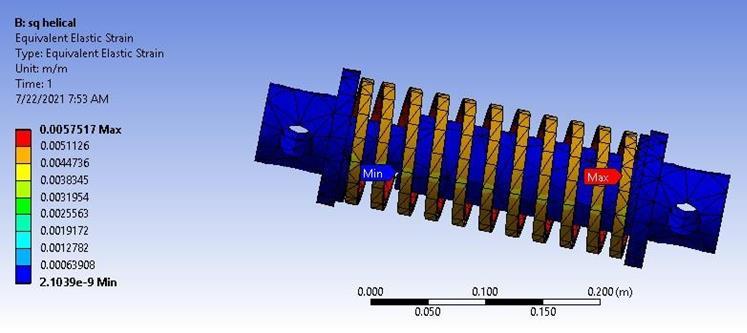
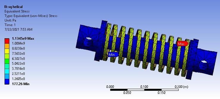
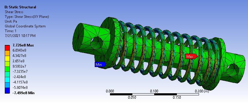
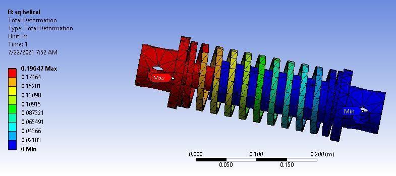
International Research Journal of Engineering and Technology (IRJET) e ISSN: 2395 0056 Volume: 08 Issue: 12 | Dec 2021 www.irjet.net p ISSN: 2395 0072 © 2021, IRJET | Impact Factor value: 7.529 | ISO 9001:2008 Certified Journal | Page727 6. RESULTS AND DISCUSSION Table6.1ResultsforLowCarbonSteelMaterialforLoadOf2750N SPRINGCROSSSECTION CircularHelical EllipticalHelical SquareHelical Maximum Minimum Maximum Minimum Maximum Minimum TotalDeformation 0.29548 0 0.054516 0 0.19647 0 EquivalentElasticStrain 0.008381 3.49E 10 0.002927 2.67E 14 0.0057517 2.10E 09 EquivalentVonmisesStress 1.55E+09 31.496 5.66E+08 0.0020144 1.13E+09 117.26 ShearStress 7.73E+08 7.50E+08 3.03E+08 3.10E+08 5.52E+08 5.52E+08 ShearElasticStrain 0.010692 0.010377 0.00418 0.00043 0.00764 0.00764 Table6.2ResultsforLowCarbonSteelMaterialforLoadof4000N SPRINGCROSSSECTION CircularHelical EllipticalHelical SquareHelical Maximum Minimum Maximum Minimum Maximum Minimum TotalDeformation 0.42979 0 0.079296 0 0.28578 0 EquivalentElasticStrain 0.01219 5.0812e 10 0.004257 3.8871e 14 0.0083661 3.0602e 9 EquivalentVonmisesStress 2.2516e9 45.813 8.2272e8 0.00293 1.6502e9 257.83 ShearStress 1.238e9 1.0908e9 4.4002e8 4.5108e8 8.031e8 8.0304e8 ShearElasticStrain 0.015551 0.015094 0.00608 0.00624 0.01114 0.01113 Table6.3ResultsforChromiumVanadiumSteelMaterialforLoadof2750N SPRINGCROSSSECTION CircularHelical EllipticalHelical SquareHelical Maximum Minimum Maximum Minimum Maximum Minimum TotalDeformation 0.26826 0 0.049556 0 0.16856 0 EquivalentElasticStrain 0.0080453 2.9969e 10 0.002846 4.7802e 15 0.0053357 1.7722e 9 EquivalentVonmisesStress 1.5334e9 23.787 5.7593e8 0.00275 1.002e9 110.83 ShearStress 7.6391e8 4.517e8 3.8787e8 3.1568e8 5.4096e8 5.4092e8 ShearElasticStrain 0.009373 0.0092249 0.00377 0.003873 0.006637 0.006643 Table6.4ResultsforLowCarbonSteelMaterialforLoadof4000N SPRINGCROSSSECTION CircularHelical EllipticalHelical SquareHelical Maximum Minimum Maximum Minimum Maximum Minimum TotalDeformation 0.39019 0 0.072082 0 0.25478 0 EquivalentElasticStrain 0.011702 4.3591e 10 0.00414 6.9531e 15 0.0080539 2.6749e 9 EquivalentVonmisesStress 2.2595e9 34.6 8.3772e8 0.004 1.6614e9 166.45 ShearStress 1.111e9 1.0935e9 4.4782e8 4.5918e8 8.1655e8 8.0654e8 ShearElasticStrain 0.013634 0.01348 0.00549 0.005635 0.017019 0.011349
International Research Journal of Engineering and Technology (IRJET) e ISSN: 2395 0056 Volume: 08 Issue: 12 | Dec 2021 www.irjet.net p ISSN: 2395 0072 © 2021, IRJET | Impact Factor value: 7.529 | ISO 9001:2008 Certified Journal | Page728
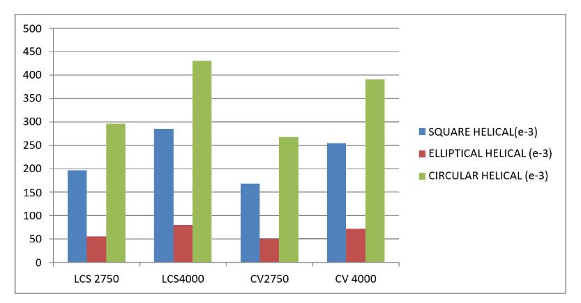
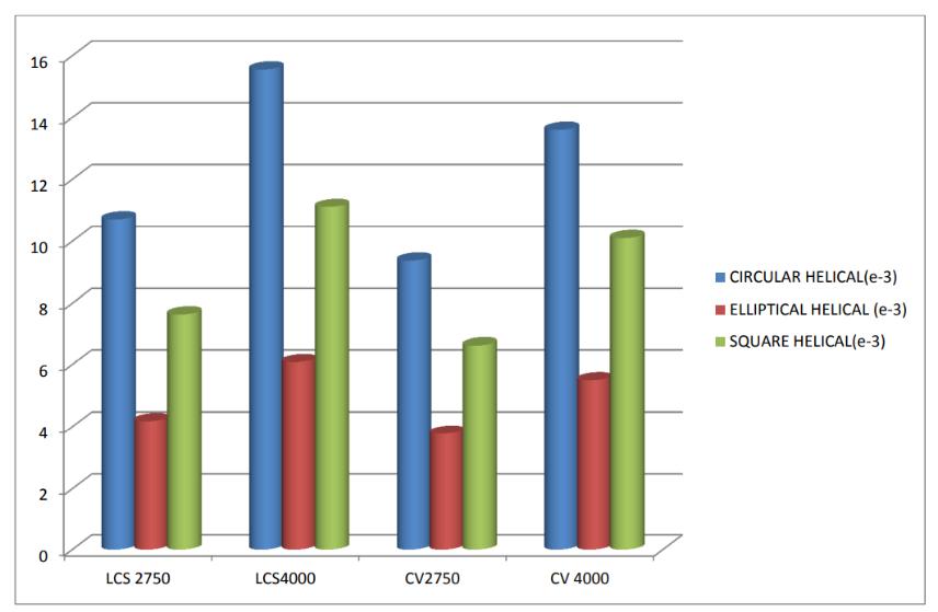
6.1 Comparison of Different Cross section
Fig 6.1: ComparisonofTotalDeformation
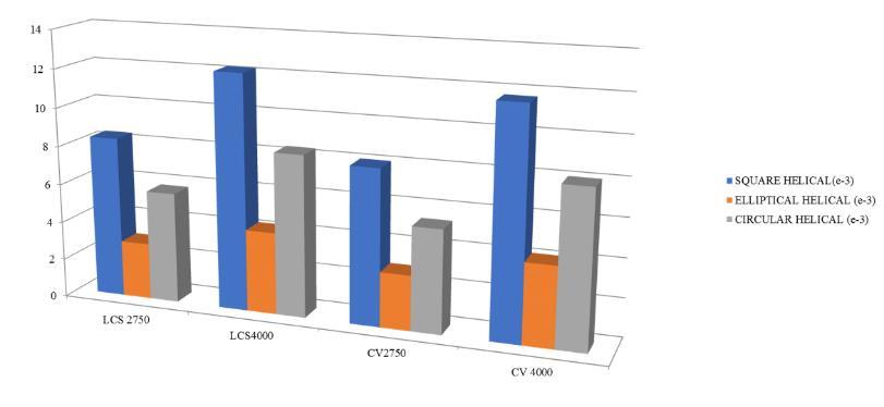
Fig 6.2: ComparisonofEquivalentElasticStrain
Low carbon steel, despite its high cost, has benefits for the suspension system, such as reduced weight and greater strength.
Total deformation, elastic strain, equivalent (von mises) stresses, maximal shear stresses, and shear strain are tabulated,andgraphscontainingthoseresultsarepresented to Deformation,study. strain, stress, and shear stress rose when the loadwasraisedfrom2750Nto4000Nforvariousmaterials, matching respective cross sections were created using ANSYS 17.2 software, and the pictures are displayed in the figures.
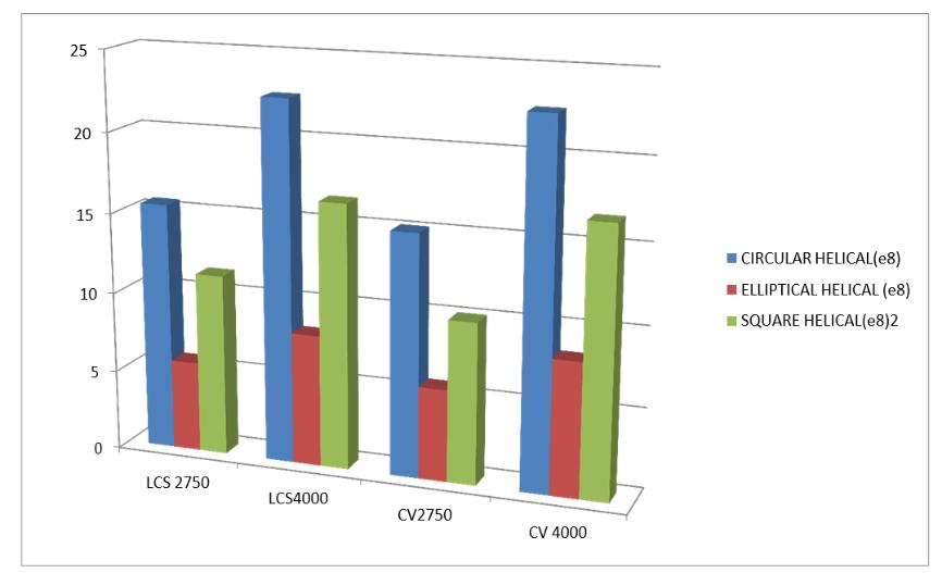
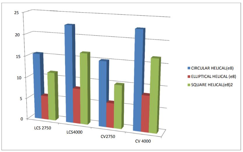
Fig 6.3: ComparisonofEquivalentVonMisesStress
Fig 6.4: ComparisonofEquivalentShearStrain
Fig 6.5: ComparisonofShearStress
Whencomparedtototaldeformationinchromiumvanadium steel, low carbon steel showed a 48 percent reduction in Whendeformation.theload is raised, the total deformation, shear strain, andshearstressallrise. The stress and shear stress of the two materials are almost equivalent under the same load (tested under a load of 2750N,4000N).
International Research Journal of Engineering and Technology (IRJET) e ISSN: 2395 0056 Volume: 08 Issue: 12 | Dec 2021 www.irjet.net p ISSN: 2395 0072 © 2021, IRJET | Impact Factor value: 7.529 | ISO 9001:2008 Certified Journal | Page729
7. CONCLUSIONS
REFERENCES
Duringthepreliminaryinvestigation,itbecameevident thatalotofthoughthadgoneintothedesignofcircular cross section springs, especially when it came to calculatingstiffnessundervariousloadingconditions.
[1] Ancker,Jr. and J.N.Goodier, “Pitch and curvature corrections for helical springs”, Journal of Applied Mechanics, The American Society of Mechanical Engineers. [2] ArkoBanerjee,”Designandanalysisofhelicalspring profiles in an electric vehicle suspension system using finite element method” International Journal of Advance Research, Ideas and Innovations in TechnologyISSN:2454 132X
The validity of the FEA using ANSYS based on the linearity between load and deformation must be recognised before the study's conclusions can be accepted. Strain energy is used to store the work done bythedeformationofthespring'shelix.
Asverifiedbycomparisonoffindings,thestrainenergy in the finite element model properly approximated the strain energy predicted theoretically for a unit volume ofthelinearelasticspring.
[3] Vijayeshwar BV “Design and Static Analysis of Helical Suspension Spring with Different Materials” IARJSET [4] S.K. Das,"Failure analysis of a passenger car coil spring",EngineeringFailureAnalysis.
[5] N. Yaswanth Krishna,"Analysis of Helical Springs UsingCATIA V5R19andANSYS16.0".
[6] D. Datta," Analysis of prismatic springs of non circular coil shape and non prismatic springs of circular coils shape by analytical and finite element methods”, Journal of Computational Design and Engineering.
CATIA V5R19 and ANSYS 16 were used in this work to simulate and analyze a coil or helical spring, which is a key component of current automobile suspension Tosystems.model the spring under varied loads, two alternative materialswereused. For all load levels, the findings showed that the spring built of structural steel had the least amount of overall Lowdeformation.carbonsteels exhibited a 14 percent reduction in deformationwhencomparedtochromevanadiumsteels.