International Research Journal of Engineering and Technology (IRJET)
e-ISSN: 2395-0056
Volume: 08 Issue: 12 | Dec 2021
p-ISSN: 2395-0072
www.irjet.net
Coplanar Waveguide-Fed Micro-strip Patched Antenna at 2.4 GHz Nisha1, Hari Ram Tanwar1 1Electronics
and Communication Engineering Department, Suresh Gyan Vihar University, Jaipur, Rajasthan, India ---------------------------------------------------------------------***----------------------------------------------------------------------
Abstract - In the past few years, microstrip antennas have
much more attention due to their attractive features. The increase in demands of high data transfers through a wireless link, tiny size antennas utilized for various purposes. This paper present the fabricate and simulation of a coplanar waveguide fed (CPW) microstrip patch antenna at resonant frequency 2.4 GHz used for WLAN applications. The patch elements have been placed on the FR-4 epoxy substrate with a relative dielectric constant of 4.4 at the height of 1.6mm. Simulated results are obtained using Ansoft HFSS 11 software, a full-wave electromagnetic field simulator for arbitrary 3D volumetric passive device modeling that takes advantage of the familiar Microsoft Windows graphical user interface. The maximum gain that the proposed patch antenna has achieved is 9.9 dB at a GHz band.
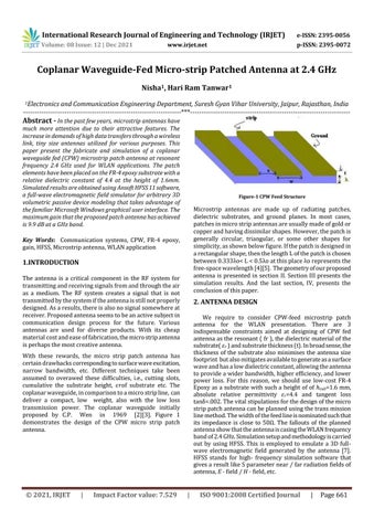
Figure-1 CPW Feed Structure
Microstrip antennas are made up of radiating patches, dielectric substrates, and ground planes. In most cases, patches in micro strip antennas are usually made of gold or copper and having dissimilar shapes. However, the patch is generally circular, triangular, or some other shapes for simplicity, as shown below figure. If the patch is designed in a rectangular shape, then the length L of the patch is chosen between 0.333λo< L < 0.5λo at this place λo represents the free-space wavelength [4][5]. The geometry of our proposed antenna is presented in section II. Section III presents the simulation results. And the last section, IV, presents the conclusion of this paper.
Key Words: Communication systems, CPW, FR-4 epoxy, gain, HFSS, Microstrip antenna, WLAN application
1.INTRODUCTION The antenna is a critical component in the RF system for transmitting and receiving signals from and through the air as a medium. The RF system creates a signal that is not transmitted by the system if the antenna is still not properly designed. As a results, there is also no signal somewhere at receiver. Proposed antenna seems to be an active subject in communication design process for the future. Various antennas are used for diverse products. With its cheap material cost and ease of fabrication, the micro strip antenna is perhaps the most creative antenna.
2. ANTENNA DESIGN We require to consider CPW-feed microstrip patch antenna for the WLAN presentation. There are 3 indispensable constraints aimed at designing of CPW fed antenna as the resonant ( fr ), the dielectric material of the substrate( 𝜀𝑟 ) and substrate thickness (t). In broad sense, the thickness of the substrate also minimises the antenna size footprint but also mitigates available to generate as a surface wave and has a low dielectric constant, allowing the antenna to provide a wider bandwidth, higher efficiency, and lower power loss. For this reason, we should use low-cost FR-4 Epoxy as a substrate with such a height of of 𝑠𝑢𝑏=1.6 mm, absolute relative permittivity 𝜀𝑟=4.4 and tangent loss tanδ=.002. The vital stipulations for the design of the micro strip patch antenna can be planned using the trans mission line method. The width of the feed line is nominated such that its impedance is close to 50Ω. The fallouts of the planned antenna show that the antenna is casing the WLAN frequency band of 2.4 GHz. Simulation setup and methodology is carried out by using HFSS. This is employed to emulate a 3D fullwave electromagnetic field generated by the antenna [7]. HFSS stands for high- frequency simulation software that gives a result like S parameter near / far radiation fields of antenna, E - field / H - field, etc.
With these rewards, the micro strip patch antenna has certain drawbacks corresponding to surface wave excitation, narrow bandwidth, etc. Different techniques take been assumed to overawed these difficulties, i.e., cutting slots, cumulative the substrate height, 𝜖𝑟of substrate etc. The coplanar waveguide, in comparison to a micro strip line, can deliver a compact, low weight, also with the low loss transmission power. The coplanar waveguide initially proposed by C.P. Wen in 1969 [2][3]. Figure 1 demonstrates the design of the CPW micro strip patch antenna.
© 2021, IRJET
|
Impact Factor value: 7.529
|
ISO 9001:2008 Certified Journal
|
Page 661