International Research Journal of Engineering and Technology (IRJET) e ISSN: 2395 0056 Volume: 08 Issue: 12 | Dec 2021 www.irjet.net p-ISSN: 2395-0072 © 2021, IRJET | Impact Factor value: 7.529 | ISO 9001:2008 Certified Journal | Page588 DESIGN AND FINITE ELEMENTS ANALYSIS OF ATV ROLLCAGE MODELING Ayush Vishwakarma
The Society of Automotive Engineers (SAE) sponsors design contests to familiarise students with the fundamentals of mobility engineering. The SAEINDIA BAJA incident, conducted each time in Pithampur, is one such scholar to design activity. The SAE BAJA vehicle development handbook establishes limitations on the vehicle's weight, shape, and size, as well as its measurements. The SAE BAJA competition's aim is to mimic real world engineering design projects and the problemsassociatedwiththem.Additionally,itproducesthehighestperformancevehiclepossiblewitharobustandcost effectivevehiclestructurethatmeetsallSAEBAJAdesignstandards.Anyvehicleissubjectedtoloadsduringnormalroad operationthatgeneratestrains,vibrations,andnoiseinthevariouscomponentsofitsstructure.Thisneedscomponentsto have enough strength, stiffness, and fatigue characteristics in order to withstand these stresses (Raina et al., 2015). AppropriatematerialselectionisseriousinthestrategyandexpansionofATVchassis.Numerouspapersandtheseshave beenproducedonthissubject,howeverthemajorityofthearound190publicationsfocusedontheaccidents andinjuries sustained when extreme off roading on ATVs. Consistent with safety considerations and chassis strength, it should be capableofwithstandingthetremendousstressescreatedduringATVoperation.Materialselectionforrollcageproduction includes AISI 1018, AISI 4130, AISI 1020, E Glass epoxy, and carbon fiber, and numerous other criteria such as cross section, vehicle design ergonomics, and factor of safety (FOS) are also addressed (Dubey et al., 2021). GeoSTAR® was utilizedtodemonstratethesafetyofthechassisdesignduetoitsminimalmemoryneeds.Staticinvestigationwasdoneon afiniteelement(FE)modelgeneratedinANSYSutilizingthe'Pipe16'element.Simulatingtheissuestatementwasthenext stage, which involved selecting appropriate material characteristics, cross sectional parameters, positioning restrictions,
UG student, Department of Mechanical Engineering, Lakshmi Narain College of Technology, Raisen road, Bhopal (M.P)***
Abstract: The American National Standards Institute (ANSI) defines an ATV: all terrain vehicle, also known as a quad bike, quad, three wheeler, or four wheeler, as a vehicle that drives on low pressure tyres, has a seat that the operative straddles, and handlebars for steering control. An ATV's skeleton is called a roll cage. The roll cage serves as both a structural foundation and a three dimensional shell that protects the occupant in the event of a collision or a rollover. Therollcagealsoimprovesavehicle'sappearance.Thepurposeofthisarticleistodiscussthedesignofarollcageforan ATV. Numerous loading tests were carried out, including front impression, side influence, and rear influence. ANSYS softwarewasusedformodellingandstressinvestigation.Weconcentratedoneveryareaoftherollcagetoincreasethe vehicle'sperformancewhileavoidingrollcagefailure.Thevehiclefixedgeometryfindingsforthesuspensionmountings andthesuspensionmountingsonthebaseplane,aswellasthefrontimpact(case1),frontimpact(case2),rearimpact (case 2), side impact (case 2), rollover (case 2), and torsional analysis (case 3). The following frequencies were determined: 6G, 4G, 5G, 3.5G, 3.5G, and 5G. The work energy concept was used to determine the force. The maximum equivalentstress(MPa)mustbe256.3MPabecausetothedifficultterrainandroute.Torsionanalysislimitsthefrontand rearsuspensionofanATV.
Keywords: All terrainvehicle(ATV);rollcage;design;RULEBOOK;impact
Introduction All terrainvehicleswereclassifiedbytheAmericanNationalStandardInstituteasvehicleswiththreeorfourlow pressure tyres with a driver straddling the seat and guiding the vehicle. As the name indicates, the ATV can manage a range of terrains and is more adept at driving on gravel roads than most other vehicles (Soundararajan et al., 2021). During movement,thevehicleissubjectedtodynamicandstaticstresses.Steeringonunevensurfacesgeneratesdynamicloadson the vehicle and static loads on the stationary vehicle; braking, acceleration, cornering, and torsion generate the extreme loadontheobverseaxle,themaximumloadof therearaxleisproducedastaticstressonthevehicle.Thedesignmustbe ergonomic,andsufficientstrengthmustbeachievedwhileminimizingcostsandmaintainingareasonablylowweightfor rough terrain use. Contemporary designs are over configured, i.e., the sturdiness exceeds the necessity, resulting in additionalweightandproductioncosts(Aakashetal.,2020).All terrainvehiclesandsnowmobilesareextensivelyutilized forvocationalandrecreationalreasonsacrosstheworld,andtheirpopularitycontinuestogrow.Inthepast,asvehicleuse grew, fatalities and injuries caused by vehicle design, topography, crashes, and rider conduct increased proportionately. Manufacturers,associations,organizations,governmentagencies,andconsumergroupshaveworkedforyearstoenhance thedesignofthesevehicles'safetyfeaturesandridinghabits(Gilkeyetal.,2021).

Table 1: The comparison of different grades of steel.
CAD Model Preparation
Parameters AISI 1018 AISI 1040 AISI 1020 Densitykg/m3 7700,7845,7700,7700,7700 Ultimatestrength N/mm2 634,518.08,560,580,394.7 YieldStrengthN/mm2 388,353.4,480,430,294.8
International Research Journal of Engineering and Technology (IRJET) e ISSN: 2395 0056 Volume: 08 Issue: 12 | Dec 2021 www.irjet.net p-ISSN: 2395-0072
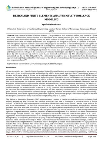
The material specification above is chosen by optimizing the weight and maximum stress generated during simulation usingtheheuristictuningapproach.TherollcagemodelwascreatedusingSOLIDWORKS 2018,takingintoaccountallof thedimensionsspecifiedintheBAJARULEBOOK(Figure1).
Materials and Methods
© 2021, IRJET | Impact Factor value: 7.529 | ISO 9001:2008 Certified Journal | Page589
loading circumstances, and mesh component size. The research illustrates the Von Misses stress distribution and the deformation of the frame components under load. If it was determined that the stress created in the chassis members exceededthematerial'syieldpoint,thecurrentframewaschangedtoprovideasafedesign.Therevised designwasthen submitted to the same analysis, and iterations were performed until the stress and deformation remained within the required range (Khanzode et al., 2016). FEA: Finite element analysis is determined if a product will wear out, fail, or performasintended(Dusaneetal.,2016).Thepurposeofthisprojectwastobuildtherollcageutilizingthesamematerial for the primary and secondary frames. The roll cage was built using the BAJA SAE 2019 RULEBOOK as a guide. After developingarollcage,itwassubjectedtonon destructiveanalysis,namelyfiniteelementanalysis(FEA)simulation.This research offered simulations such as impact tests and torsional tests of roll cages that must be conducted prior to beginningrollcageproduction.
According to the SAE RULEBOOK, the roll cage frame was composed primarily of two types of members (primary and secondarymember).Teamswerechosentobuildthewholerollcageusingthesamematerialgradeandthicknessortouse a material grade and thickness that differs. To maximize the material's cost effectiveness and strength, both the primary andsecondarycomponentsoftherollcagearemadefromthesamematerial,i.e.,4130AISI.
As stated in the "material procurement" section, AISI 4130 is used for the ATV roll cage's fabrication. The following specificationsareusedtochoosethematerial: ID=25.4mm; OD=19.4mm Thickness=3mm
Young’sModulusGap 200,200,200,200,200 HardnessBHN 197,149,156,379,111
Theresearchworkwasinitiatedwithathoroughmarket study.Thematerialselectionprocessisacriticalfirststepinthe design and manufacture of a roll cage. The SAE BAJA RULEBOOK specifies that the chassis material must include at least 0.18percentcarbon. Asa result,themarketoffersa diverserangeofmaterialsthatarepermissibleforusage, and teams haveavarietyofgradeswithineachtypeofmaterialfromwhichtochoosethebestfortheapplication.Numerousaspects influence the material selection process, including cost, market availability, weight, mechanical and chemical characteristics,andmachinability(Table1).
ToconductFEAontheexistingandchangedKnuckle,a3DmodelisbuiltinCATIAv5andsavedinIGSformat.Themodelis then loaded into ANSYS 12.0. Engineering data has been used to give the material characteristics shown in Table 1. The model isa meshconstructedusingthe Solid187 hexahedral 10 nodeelement. Three degrees offreedomareavailableto solidelements,namelytranslationintheX,Y,andZdirections.Thefiniteelementanalysisoftheknucklewasperformed forvariousboundaryconditionsandthestresslevelwasdeterminedaccordingtothematerialpropertyofthematerial.All findingsobtainedusing ANSYS12.0aretabulated. of Impact Force Weight(withdriver) MkgF forceofimpactN velocitybeforeimpactm/s m/s(velocityafterimpact)(FromNewton’sSecondLawOfMotionF=MA) AlsoweknowA=dv/dtF=M(dv/dt) Where,A=acceleration invelocity(Vi Vf)dt=timeofimpact(sec) G1G=M(g) (Whereg=accelerationduetogravitySoletWeight(withdriver) 240kgF forceofimpactN) Vf=013.88m/sm/s(velocityafterimpact) FromNewton’sSecondLawOfMotionF=MAAlsoweknowA=dv/dtF=M(dv/dt) dv=changeA=accelerationinvelocity(Vi Vf)dt=timeofimpact(sec) termsofG, Whichwasapproximatelyequalto4G.
dv=change
International Research Journal of Engineering and Technology (IRJET) e ISSN: 2395 0056 Volume: 08 Issue: 12 | Dec 2021 www.irjet.net p-ISSN: 2395-0072 © 2021, IRJET | Impact Factor value: 7.529 | ISO 9001:2008 Certified Journal | Page590
Vf=0
Figure 1: A: Top view Fig 1: B: Isometric view. Finite Element Analysis (FEA)
Calculation
InTherefore,termsof
Vi=
Where,
Vi=
NowF=9517.71Nforcein

International Research Journal of Engineering and Technology (IRJET) e ISSN: 2395 0056 Volume: 08 Issue: 12 | Dec 2021 www.irjet.net p-ISSN: 2395-0072 © 2021, IRJET | Impact Factor value: 7.529 | ISO 9001:2008 Certified Journal | Page591
Table 2: Thefrontimpactbehaviorofthememberontheinteractionwiththeforce
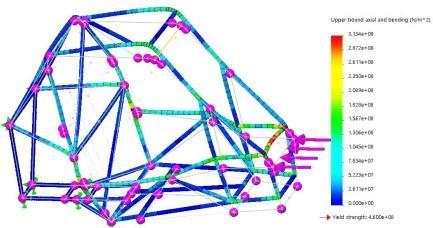
Fixed geometry Rear suspension mountings Force applied(G) 6G Impact time(sec) 0.25 Max equivalent stress (MPa) 313.4 Displacement(mm) 4.955 FOS 1.5
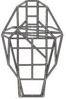
Front Impact In front impact testing, there were two distinct scenarios: the ATV colliding with a wall (a nondeformable object) or colliding with another ATV,tree, etc (which is a deformable object). As a result, the timing of effect was different in both situations.Theimpacttimewaslongerinthe deformableobjectscenario(say0.25seconds)thaninthenon deformable objectcase(say0.35seconds).Therearsuspensionmountingsoftherollcagewerefixed(DOF=0)duringthefront impact test,andaforceof6G(fornon deformable)or4G(fornon deformable)wasappliedtotherollcage'sfront mostmember (frontlateralcross memberFLC).Themember'sactivityinresponsetotheforceisdepictedinFigure2,3andTable2,3.
Figure 3: Thefrontimpactbehaviorofthememberontheinteractionwiththeforce.
Fixed geometry Rear suspension mountings Force applied(G) 4G Impact time(sec) 0.35 Max equivalent stress (MPa) 223.8 Displacement(mm) 3.539 FOS 2.1
Figure 2: Thefrontimpactbehaviorofthememberontheinteractionwiththeforce.
Table 3: Thefrontimpactbehaviorofthememberontheinteractionwiththeforce

Side Impact Bothitems,liketherearimpact,aremalleable.Thus,whenaforceisdeliveredfromthe left sideoftheATV,therightside suspensionmountingsoftherollcagearefixed(DOF=0),and a3Gforceisappliedtotherollcage'sleftmostmember(side impactmemberSIM).Thediagramdepictsthemember'sbehaviourinresponsetotheappliedforce(Figure5andTable5).
Table 4: Therearimpactbehaviorofthememberontheinteractionwiththeforce.
International Research Journal of Engineering and Technology (IRJET) e ISSN: 2395 0056 Volume: 08 Issue: 12 | Dec 2021 www.irjet.net p-ISSN: 2395-0072 © 2021, IRJET | Impact Factor value: 7.529 | ISO 9001:2008 Certified Journal | Page592
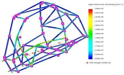
Rear Impact DuetothelackofareversegearonmostSAEBAJAATVs,itisassumedthattheATVwasstruckbyanotherATV,resulting ina deformableobject.Asa result, the risk ofcolliding witha wall isaverted. Asa result,inthe rearimpacttest,the roll cage'sfrontsuspensionmountingsarefixed(DOF=0),anda5Gforceisdeliveredtotherollcage'srearmostmember(rear lateral cross member RLC). The figure illustrates the member's behaviour in relation to the applied force (Figure 4 and Table4).
Figure 4: Therearimpactbehaviorofthememberontheinteractionwiththeforce. Fixed geometry Rear suspension mountings Force applied(G) 5G Max equivalent stress (MPa) 158.9mpa Displacement(mm) 2.55mm FOS 2.89

Rollover
Table 5: Thesideimpactbehaviorofthememberontheinteractionwiththeforce Intheeventofarollover,theATVisthrownoverboardduringdownhillacceleration.Therollcageisdesignedtosafeguard theoccupantintheeventofanaccidentorrollover.In therollovertest,therollcage'ssuspensionmountings,i.e.thebase planer, are fixed (DOF=0), and a force of 4G is applied to the roll cage's upper lateral cross member (CLC). The graphic depictsthemember'sactivityinresponsetotheappliedforce((Figure6andTable6).
Figure 6: The rollover behavior of the member on the interaction with the force.
International Research Journal of Engineering and Technology (IRJET) e ISSN: 2395 0056 Volume: 08 Issue: 12 | Dec 2021 www.irjet.net p-ISSN: 2395-0072 © 2021, IRJET | Impact Factor value: 7.529 | ISO 9001:2008 Certified Journal | Page593 Figure 5: The side impact behavior of the member on the interaction with the force. Fixed geometry Rear suspension mountings Force applied(G) 3.5G Max equivalent stress (MPa) 309.5mpa Displacement(mm) 8.94mm FOS 1.5

International Research Journal of Engineering and Technology (IRJET) e ISSN: 2395 0056 Volume: 08 Issue: 12 | Dec 2021 www.irjet.net p-ISSN: 2395-0072
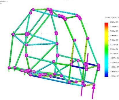
Figure 7: Thetorsionalanalysisofthememberontheinteractionwiththeforce.
Torsional Analysis
Modal analysis was the study of monitoring and evaluating the dynamic response of structures and or fluids during stimulation. The study was conducted by the Department ofTransportation. Normal Modes Analysis, sometimes termed eigenvalueanalysisoreigenvalueextraction,wastechniqueusedtocomputethevibrationformsandrelatedfrequencies thatastructurewasdisplay. Itwascrucialtoknowthesefrequenciesbecauseifcyclicloadswereappliedatcertainfrequencies,thestructurecanmove into a resonance situation that was led to catastrophic failure. It was also necessary to know the forms in order to make surethatloadsarenotplacedatlocationsthatwascausingtheresonancesituation.
Displacement(mm) 2.44DEGREEINXDIRECTION FOS 1.8
Results and Discussion
Table 7: Thetorsionalanalysisofthememberontheinteractionwiththeforce.
By examining the vehicle fixed geometry of front impact (case1), front impact (case2), rear impact side impact, rollover, Fixed geometry Suspension mountings on the base plane Force applied(G) 3.5G Max equivalent stress (MPa) 321.7 Displacement(mm) 6.49 FOS 1.43
The rearsuspension mountingsoftheroll cagearefixed(DOF=0)inthistorsional study,whereasa coupleforceof4Gis given to the front suspension mountings. The graphic depicts the member's activity in response to the applied force (Figure7andTable7).
© 2021, IRJET | Impact Factor value: 7.529 | ISO 9001:2008 Certified Journal | Page594
Table 6: Therolloverbehaviorofthememberontheinteractionwiththeforce.
Fixed geometry Rear suspension mountings Force applied(G) 5G Max equivalent stress (MPa) 256.3
adhering
Conclusion Itwasconcludedfromthepresentresearchthatthefrontimpact(case1),frontimpact(case2),rearimpact(case2),side impact (case 2), rollover (case 2), and torsional analysis (case 3),the vehicle fixed geometry findings for the suspension mountings and the suspension mountings on the base plane. 6G, 4G, 5G, 3.5G, 3.5G, and 5G were determined. The side impact test was performed to simulate a collision with another ATV, and the findings are used to determine future protectionmeasures.Duringtherearcrash,moreATVsmayhittheautomobilefromtheback.Therearimpactdeformation
International Research Journal of Engineering and Technology (IRJET) e ISSN: 2395 0056 Volume: 08 Issue: 12 | Dec 2021 www.irjet.net p-ISSN: 2395-0072 © 2021, IRJET | Impact Factor value: 7.529 | ISO 9001:2008 Certified Journal | Page595 and torsional analysis findings were displayed as right suspension mountings and suspension mountings on the base plane.Theforcecomputedbyvehiclefixedgeometryoffrontimpact(case1),frontimpact(case2),rearimpactsideimpact, rollover,andtorsionalanalysisfindingswerediscoveredas6G,4G,5G,3.5G,3.5Gand 5G.Duringthesideimpactanalysis, thestudyisdonetoreplicatesuchsituationswhereanother ATVwashitATVonside.Duringtherearcollision,thevehicle maygetstruckonthebackside by other ATVduring the incident. The maximum deformation for rear impact is 2.50mm.Duringtherolloverimpact,thevehiclehashighchanceofrollingoveritshoopmemberwhendrivingonahillor valley region. In these situations, the ATVis regarded tobefallen on its top on the track or ground from a height. In this example,force wascalculatedusingthework energyprinciple,and theuppersectionof the ATVfelthigher force. Due to thestiffnessofthetrackandground,themaximumequivalentstress(MPa)wasdeterminedusingtorsionalanalysistobe 256.3MPaandtheforcedeliveredtothetopportionoftheATVtobe5Gwhilemaintainingthefrontandrearsuspension constraintsconstant.Torsionstudywasperformedtodeterminethetorsionstiffnessofthechassisoverthecrossbumpin the rearand front sections of the ATV.The primary objective of the torsional study was to identify a chassis with a wide range of stiffness capable of withstanding dynamic suspension loads. The applied forces are similar in magnitude but opposing in direction. By utilizing this loading condition, the case of pure torsion was created via the fixed constraint implementedinthebackwheel(Table8). Parameters ImpactFront ImpactFront(case1) Rear(case2)Impact ImpactSide AnalysisRollover AnalysisTorsional Fixed Geometry mountingssuspensionFront mountingsuspensionFront mountingssuspensioRearn mountingssuspensionRight rearplaneonMountingthebase mountingssuspension Applied(G)Force 6G 4G 5G 3.5G 3.5G 5G Equivalent stress (MPa) Max. 313.4 223.8 158.9 309.5 321.7 256.3 inDeformation(mm)Xdirection 2.44 3.314 3.539 2.50 8.94 6.49 FOS 1.5 2.24 2.89 1.5 1.43 1.8 Table 8: Resultanalysisoffrontimpact(case1),frontimpact(case2),rearimpact,sideimpactrolloverandtorsional analysis.
occurred
Driver safety is paramount in any motorsport event, and an analysis of fatalities revealed that the majority of fatalities asaresultofhead oncollisions.SAEBajarequiresstudentteamstoconstructanATVvehiclefromthegroundup, to the rules specified by the governing bodies. The FEA study established that the structural advantage was achieved while retaining a low weight to strength ratio. Customers' demands were prioritized because they are our ultimate aim. While maneuvering over difficult terrain, the vehicle exhibited acceptable dynamic stability (Garg and Raman, 2013). Maximum Stress, Maximum Deformation, and Factor of Safety values obtained are well within the range specified in the Baja SAE rulebook and previously published papers (Dubey et al., 2021). Torque is delivered to one tyre andrespondedtobytheopposingtyre,generatingapairthatattemptstotwisttherollcage(Mishraetal.,2021).
2. Aakash,B.E.S.S., Reddy,D.M.,Ramachandran,B.,&Abhishikt,C.balajiN.S. (2020).Designandanalysisofroll cage chassis.MaterialsToday:Proceedings.doi:10.1016/j.matpr.2020.07.709.
5. K K Dubey,B Pathak, B K Singh, P Rathore, S R S Yadav(2021). Design and Development of All TerrainVehicleRoll Cage. IOP Conf. Series: Materials Science and Engineering 1149 (2021) 012021. doi:10.1088/1757 899X/1149/1/012021
References 1. R.Soundararajan,R.Ajith,C.Maheshkumar,U.Sabarivasan,J.SonuMourya,A novelapproachfordesignandanalysis of an all terrain vehicle roll cage, Materials Today: Proceedings, Volume 45, Part 2, 2021, Pages 2239 2247, https://doi.org/10.1016/j.matpr.2020.10.224.
6. DhruvaKhanzode,NilayAkre,andAkshayDeotale(2016).AnalysisofstressesandmaterialselectionofSAEBAJAATV Areview.IJRME InternationalJournalofResearchinMechanicalEngineering.Volume:03Issue:042016,24 29.
International Research Journal of Engineering and Technology (IRJET) e ISSN: 2395 0056 Volume: 08 Issue: 12 | Dec 2021 www.irjet.net p-ISSN: 2395-0072
3. DavidP.Gilkey,WilliamBrazile,ATV,Snowmobile,andTerrainVehicleSafety,Editor(s):RogerVickerman,International Encyclopedia of Transportation, Elsevier, 2021, Pages 77 84, https://doi.org/10.1016/B978 0 08 102671 7.10109 5
7. S V Dusane et al 2016. Analysis of Steering Knuckle of All TerrainVehicles(ATV)UsingFinite Element Analysis. IOP Conf.Ser.:Mater.Sci.Eng.1490121338.SandeepGargandRaviShankarRaman(2013).DESIGNANALYSISOFTHE ROLLCAGEFORALL TERRAINVEHICLE.IJRET:InternationalJournalofResearchinEngineeringandTechnology. Volume:02Issue:09|Sep 2
4. DeepakRaina,RahulDevGupta,RakeshKumarPhanden(2015).DesignandDevelopmentforRollCageofAll Terrain Vehicle.International Journal For Technological Research In Engineering (IJTRE). Volume2, Issue 7, March 2015, 1092 1099.
© 2021, IRJET | Impact Factor value: 7.529 | ISO 9001:2008 Certified Journal | Page596 shouldbe2.5mm. When goingup ordowna hill,theautomobileislikelyto roll overthehoop member.Aslong asthese criteriaexist,theATVisjudgedtohavefallenfromaheight.Theforcewasfoundusingthework energyprinciple.Because ofthehardterrainandtrack,themaximum equivalent stress(MPa)must be 256.3 MPa. ATV'sfrontandrearsuspension areconstrainedbytorsionalanalysis. The ATV chassiswas tested for torsional rigidity on both the rear and front ends. The torsional investigation sought to establish a robust chassis with adequate shock absorber capacity to withstand dynamic suspension loads. The two forces are of equal magnitude but opposite direction. The back wheel's fixed restrictiongeneratedpuretorsion.