International Research Journal of Engineering and Technology (IRJET)
e-ISSN: 2395-0056
Volume: 08 Issue: 01 | Jan 2021
p-ISSN: 2395-0072
www.irjet.net
Design, Analysis, and Topology Optimization of Front Upright for Electric Solar Vehicle Mani Sanguri1, Saurabh Singh2 1,2Student,
Department of Mechanical Engineering, Motilal Nehru National Institute of Technology, Allahabad, Uttar Pradesh, India ---------------------------------------------------------------------***---------------------------------------------------------------------1.1 Vehicle Specifications Abstract – This Paper consist of calculation of dynamic forces acting on Upright of an Electric Solar vehicle. Proper calculations are done to find out the value of these forces. After getting the value of Forces, Analysis and Optimization are done to Reduce the unsprung mass and thereby increasing the performance of Vehicle. Upright are one of the important unsprung mass. The main aim for Suspension system Design of the vehicle is to keep unsprung mass as low as possible. Hence, various Optimizations are carried out to get the least mass for the components, which can sustain the forces acting on the Vehicle. Upright transfers force from chassis to Ground and also absorbs forces that are caused due to motion of the vehicle.
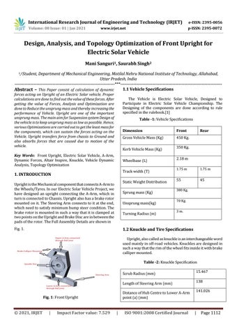
The Vehicle is Electric Solar Vehicle, Designed to Participate in Electric Solar Vehicle Championship. The Designing of the components are done according to rule specified in the rulebook.[1] Table -1: Vehicle Specifications Dimension
Front
Gross Vehicle Mass (Kg)
450 Kg.
Kerb Vehicle Mass (Kg)
Key Words: Front Upright, Electric Solar Vehicle, A-Arm, Dynamic Forces, Altair Inspire, Knuckle, Vehicle Dynamic Analysis, Topology Optimization
Wheelbase (L) Track width (T)
1. INTRODUCTION
Static Weight Distribution
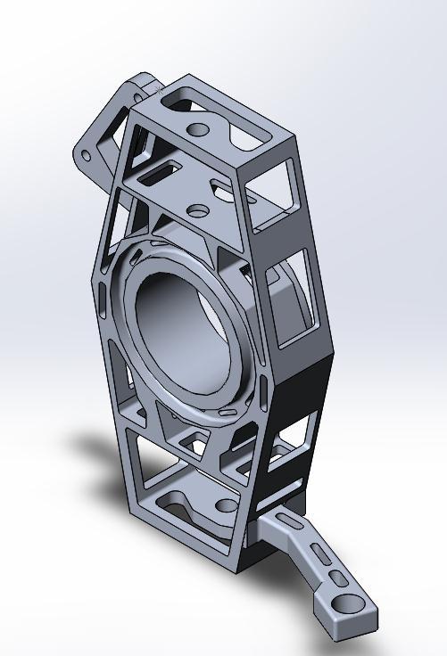
Upright is the Mechanical component that connects A-Arm to the Wheels/Tyres. In our Electric Solar Vehicle Project, we have designed an upright connecting the A-Arm, which in turn is connected to Chassis. Upright also has a brake rotor mounted on it. The Steering Arm connects to it at the end, which need to satisfy minimum bump steer condition. The brake rotor is mounted in such a way that it is clamped at two points on the Upright and Brake Disc are in between the pads of the rotor. The Full Assembly Details are shown in
Sprung mass (Kg) Unsprung mass(kg) Turning Radius (m)
Fig. 1.
Rear
350 Kg. 2.18 m 1.75 m
1.75 m
55
45
380 Kg. 70 Kg. 3 m.
1.2 Knuckle and Tire Specifications Upright, also called as knuckle is an interchangeable word used mainly in off-road vehicles. Knuckles are designed in such a way that the rim of the wheel fits inside it with brake calliper mounted. Table -2: Knuckle Specification Scrub Radius (mm) Length of Steering Arm (mm) Distance of Hub Centre to Lower A-Arm point (a) (mm)
Fig. 1: Front Upright
Š 2021, IRJET
|
Impact Factor value: 7.529
|
ISO 9001:2008 Certified Journal
15.467 138 141.026
|
Page 1112