International Research Journal of Engineering and Technology (IRJET)
e-ISSN: 2395-0056
Volume: 08 Issue: 11 | Nov 2021
p-ISSN: 2395-0072
www.irjet.net
POWER QUALITY IMPROVEMENT IN DISTRIBUTION SYSTEM USING IRPT BASED DSTATCOM Shilpi Sahu1, Shashank Kumar2, Vishnu Kumar Sahu3 1M.TECH
Scholor, Department of EE SSCET, Bhilai India Professor, Department of EEE SSGI SSTC, Bhilai, India. 3Assistant Professor, Department of EE SSGI SSTC, Bhilai, India. ----------------------------------------------------------------------***--------------------------------------------------------------------2Assistant
Abstract - This paper introduces the Modeled
generators. The solution to improving power supply quality is to use custom power supply equipment [3] such as DSTATCOM. The control schemes reported in the literature for DSTATCOM control are a scheme based on synchronous reference frame theory (SRF), current compensation using DC bus regulation, instantaneous reactive power (IRP) theory, neural network techniques [4].
Distribution Static Compensator (DSTATCOM) in the MATLAB SIMULINK Toolkit to reduce power quality problems in distribution systems. DSTATCOM is one of the custom power equipment used in power conditioning distribution system. DSTATCOM was developed to compensate for the reactive power demanded by non-linear and unbalanced loads. The source power factor is also improved and the total harmonic distortion in the source currents is reduced. DSTATCOM can heal brownouts, inflammation and imbalance by injecting reactive current into the system. The instantaneous reactive power principle is used to obtain the reference source current to control the DSTATCOM. Static Distribution Compensator (DSTATCOM) has become a potential option to reduce power quality (PQ) problems in distribution networks with non-linear loads. Basically, DSTATCOM maintains the PCC voltage and inverter intermediate circuit voltage using two PI controllers AC and DC. These gain values are typically calculated by Pi controllers based on a model-based or trialand-error method. This paper presents a comparative study of an optimization-based approach to obtain kp and ki values of a pi controller.
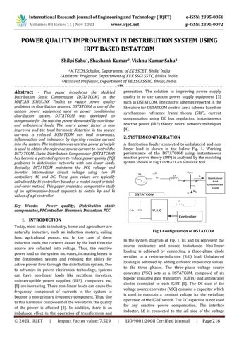
2. SYSTEM CONFIGURATION A distribution feeder connected to unbalanced and non linear load is shown in the below Fig. 1. Working performance of the DSTATCOM using instantaneous reactive power theory (IRP) is analyzed by the modeling system shown in Fig.1 in MATLAB Simulink tool.
Key Words: Power quality, Distribution static compensator, PI Controller, Harmonic Distortion, PCC
1. INTRODUCTION Today, most loads in industry, home and agriculture are naturally inductive, such as induction motors, ceiling fans, agricultural pumps, etc. In the case of these inductive loads, the currents drawn by the load from the source are collected into voltage. Thus, the reactive power load on the system increases, increasing losses in the distribution system and reducing the ability for active power flow through the distribution system. Due to advances in power electronics technology, systems can have non-linear loads like rectifiers, inverters, uninterruptible power supplies (UPS), computers, etc. [1] are increasing. These non-linear loads can cause the frequency component of currents in the system to become a non-primary frequency component. Thus, due to this harmonic component of the waveform, the quality of the power is affected [2]. In addition, there is an imbalance effect in the operation of transformers and
© 2021, IRJET
|
Impact Factor value: 7.529
Fig.1.Configuration of DSTATCOM In the system diagram of Fig. 1, Rs and Ls represent the source resistance and source inductance. Non-linear loading is achieved by connecting a three-phase diode rectifier to a resistive-inductive (R-L) load. Unbalanced loading is achieved by adding different impedance values to the three phases. The three-phase voltage source converter (VSC) acts as a DSTATCOM, composed of six bipolar insulated gate transistors (IGBTs) and antiparallel diodes connected to each IGBT [5]. The DC side of the voltage source converter (VSC) contains a capacitor which is used to maintain a constant voltage for the switching operation of the IGBT switch. The DC capacitor is not used for any reactive power compensation. The interface inductor, Lf, is connected to the AC side of the voltage
|
ISO 9001:2008 Certified Journal
|
Page 216