International Research Journal of Engineering and Technology (IRJET)
e-ISSN: 2395-0056
Volume: 08 Issue: 11 | Nov 2021
p-ISSN: 2395-0072
www.irjet.net
Error Detection and Correction using Decimal Matrix Algorithm P.Pushpalatha1, Kundeti Harshavardhan2 1Assistant
Professor, JNTUK, Andhra Pradesh M.Tech, JNTUK, Andhra Pradesh ---------------------------------------------------------------------***---------------------------------------------------------------------2Student,
Abstract - Decimal matrix code (DMC) is grounded on
dividing the information bits into symbols and is suggested to improve memory reliability with lesser delay overhead. A concern when using memories is that they can be affected by soft errors that corrupt the stored bits. The DMC technique utilizes a decimal algorithm to gain the maximum error detection capability and furthermore, the encoder-reuse technique (ERT) is suggested to reduce the area overhead of extra circuits without intervening in the entire encoding and decoding processes. Key Words: Decimal matrix code, Encoder reuse technique, Soft errors.
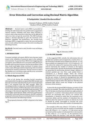
Fig -1: Schematic of DMC
1. INTRODUCTION
2. 32-Bit DMC Encoder
Transient multiple cell upsets (MCUs) have become major issues in the reliability of memories open to the radiation environments. To prevent these MCUs from triggering data corruption, more difficult error correction codes (ECCs) are broadly used to protect memory, but the key problem is that they would need higher delay overhead. In modern times matrix codes (MCs) grounded on hamming codes have been projected for memory protection. The key concern is that it has double error correction codes and the error correction abilities are not increased in all cases.
In the suggested DMC, initially, the information bits are divided into symbols and arranged into a matrix form, i.e., the N-bit data is divided into k symbols of m bits (N = k × m), these symbols are organized in a k1 × k2 2-D matrix (k = k1 × k2, where the values of k1 represent the number of rows and k2 represents the number of columns in the logical matrix respectively). Second, the horizontal redundant bits H are generated by performing decimal integer addition of selected symbols per row. Here, each symbol block is considered as a decimal integer. Third, the vertical redundant bits V are captured by binary operation among the bits per column. It should be distinguished that both dividing into symbols and arranging them in matrix form are implemented in logical rather than physical. Therefore, the proposed DMC doesn't need any change in the physical structure of the memory.
1.1 Block diagram of DMC First of all, during the encoding (write) procedure, information bits D are given as input to the DMC encoder, and then the horizontal redundant bits H and vertical redundant bits V are acquired from the DMC encoder. When the encoding procedure is done, the received DMC codeword is stored in the memory. If MCUs take place in the memory, the errors can be altered in the decoding (read) procedure. The advantage of the decimal algorithm has helped the DMC to attain higher fault-tolerant ability with lower performance overheads. In the fault-tolerant memory, the ERT method is proposed to decrease the area overhead of extra circuits and will be discussed in the following sections.
To describe the proposed DMC technique, we took a 32-bit word as an example. The cells from D0 to D31 are data bits. This 32-bit data word has been divided into eight symbols of 4-bit each. k1 = 2 and k2 = 4 have been chosen concurrently. H0–H19 are horizontal bits; V0-V15 are vertical bits. Nonetheless, it should be noted that the maximum error correction ability and the number of redundant bits are different when the values for k and m are altered. So, k and m should be wisely rearranged to increase the error correction ability and reduce the number of redundant bits.
The proposed schematic of DMC is depicted in the below figure
For example, in this case, when k = 2×2 and m = 8, only a 1-bit error can be corrected and the number of redundant bits is 80. When k = 4 × 4 and m = 2, 3-bit errors can be corrected and the number of redundant bits is decreased to 32. But, when k = 2 × 4 and m = 4, the maximum error correction ability has become 5 bits and the number of
© 2021, IRJET
|
Impact Factor value: 7.529
|
ISO 9001:2008 Certified Journal
|
Page 1076