International Research Journal of Engineering and Technology (IRJET)
e-ISSN: 2395-0056
Volume: 08 Issue: 10 | Oct 2021
p-ISSN: 2395-0072
www.irjet.net
Design and Stability Analysis of a VTOL Airplane Sainath desai1, Taha Ansari2, Adil Shaikh3, Kadir Shaikh4 1Sainath
Desai, Mechanical Engineer, Rizvi College of engineering, Maharashtra, India Ansari, Mechanical Engineer, Rizvi College of engineering, Maharashtra, India 3Adil Shaikh, Mechanical Engineer, Rizvi College of engineering, Maharashtra, India 4Kadir Shaikh, Mechanical Engineer, Rizvi College of engineering, Maharashtra, India ---------------------------------------------------------------------***---------------------------------------------------------------------2Taha
Abstract - The main purpose of the project is to eliminate the relationship between runway and airplane. Due to uneven land condition in hilly terrain building or construction of a runway will be quite challenging and uneconomical. So, it is better to use an airplane which doesn’t require a runway for takeoff and landings in such terrain. This can be achieved by using a VTOL i.e., Vertical takeoff and landing phenomenon. Airplane working on this phenomenon can be used to rescue soldiers from the borders during a war situation, by increasing the number of capacities of onboard load which can carry maximum people at a time without compromising speed. This type of performance is not at all possible to expect from a helicopter/chopper, because of its minimum load carrying capacity and speed. Not only for the above-mentioned application airplane working on this principle can also be used commercially for long or short distance transportation.
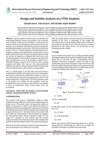
After the vehicle attains a desired velocity in which desired amount of lift force is generated in the wings the rotor/prime mover can be further tilted to Ф=0˚ which will be parallel to the land. Due to this, the amount of thrust generated by the prime mover can be focused on the acceleration of the vehicle. 2. Design Let us consider our airplane to be of 2Kg (assumed) and the thrust generated by the propeller be 4kg (assumed). After the motor tilts we see that, we have 2 components of force obtained, horizontal component which will help in the acceleration and vertical component which will act as a lift force, the angle of the tilt is decided in such a manner that the vertical component lift will be equal to weight of the vehicle so that the stalling of the vehicle is avoided.
This is a hybrid design it can also take off and land like a traditional aircraft by means of ground run. Our research for the project is restricted to unmanned air vehicle i.e., UAVs, so our model will just represent the phenomenon which can be further designed on a large extent. The thrust generates used in the project are nothing but the propellers driven by brushless Direct current motors, which is further controlled by a series of components which receive signal from the transmitter. Key Words: UAVS, VTOL, RC Airplane, Lateral Stability Analysis, Longitudinal Stability Analysis
Fig -1: Propeller Orientation FL= CosФ
1.INTRODUCTION
2x9.81= 4x9.81CosФ
The airplane will consist a streamline similar to other airplane the only difference will be of the positioning of the prime mover. The prime mover will generally consist an ability to rotate due to which it can deliver the thrust in different directions according to the requirement. During the takeoff the prime mover will be perpendicular to the ground to generate thrust in Y- direction which will act like a lift force. After the vehicle attain a desired altitude the angle of the rotor/prime mover will be switched to angle ‘Ф’. The angle ‘Ф’ is decided in such manner that the vertical component of the thrust becomes equal to the weight of the vehicle. So that the vehicle can hover at a particular altitude.
Ф= 60: On the other hand, we also calculate the horizontal thrust force THX, THx= TH SinΦ THx= 4x9.81Sin (60) THx= 34 N Hence, we see that, 34N of horizontal thrust force will be responsible for accelerating the vehicle, let us apply DeAlembert’s principle to calculate the acceleration
And the horizontal component of thrust will be help full to give acceleration to our vehicle in X- direction.
∑Fx=mxa
© 2021, IRJET
|
Impact Factor value: 7.529
|
ISO 9001:2008 Certified Journal
|
Page 1980