International Research Journal of Engineering and Technology (IRJET)
e-ISSN: 2395-0056
Volume: 07 Issue: 09 | Sep 2020
p-ISSN: 2395-0072
www.irjet.net
DEVELOPMENT OF SHELL AND TUBE HEAT EXCHANGER USING HELICAL BAFFLE PLATES ESHWAR BIRADAR M-Tech Scholar, Department of Mechanical Engineering, P.D.A College of Engineering, Kalaburgi, Karnataka. ---------------------------------------------------------------------***----------------------------------------------------------------------
Abstract - The development of Shell and Tube Heat Exchanger is the need of the new upcoming technology. The better performance of this would solve our problem of non-renewable sources of energy a lot. This paper shows all the results obtained in various numerical and CFD calculations. Further it shows the comparison between the segmental Shell and Tube Heat Exchanger with the Helical Shell and Tube Heat Exchanger Baffle plates.. This is done by two methods numerical method and CFD calculation. Baffle is a shell side component of Shell and Tube Heat Exchanger. The Helical Baffle improves the performance of the Heat Exchanger over the segmental it gives the better heat transfer rate reducing foulimng factor, etc. The desirable features of Heat Exchanger obtained a maximum heat transfer Coefficient and a lower pressure drop. From the Numerical Experimentation result the performance of Heat Exchanger is increased in Helical Baffle instead of Segmental Baffle. Key Words: Shell and Tube Heat Exchanger, CFD ANSYS Fluent, Helical Baffle plates. 1. INTRODUCTION
A Heat Exchanger is equipment built for efficient heat transfer from one medium to another. The media can be any solid or liquid bur we need the efficient heat transfer rate. There are numerous applications and are widely used in space heating, refrigeration, air conditioning, power plants, chemical plants, petrochemical plants, petroleum refineries, natural gas processing, and sewage treatment. The performed work is done on two fluids that are flowing one from the tube side and the another from the shell side. Several design parameters and operating conditions influence the optimal performance of a shell-and-tube Heat Exchanger. The Baffle configuration is selected on the basis of size, cost, and ability to lend support to the overhung tube bundles. In the presented work Helical Baffles are considered over segmental Baffles for numerous advantages such as:
Reduced shell side fouling. Reduced bypass effects. Increased heat transfer rate/ pressure drop ratio Prevention of flow induced vibration.
The segmental Baffles make fluid perpendicularly impact the shell wall and the tubes, leading to an increased power load which is overcome by Helical Baffles.
© 2020, IRJET
|
Impact Factor value: 7.529
|
The complexity with experiment will help in getting accurate results and the efficiency of the Heat Exchanger wiil be more increased more. Computational Fluid Dynamics is now an established industrial design tool, offering obvious advantages. In this study, a full 360° CFD model of Shell and Tube Heat Exchanger is considered. By modelling and geometry we get the design of Heat Exchanger that is highlyefficient. 1.1Methodology Purpose of Use of Helical Baffle: A new type of Helical Baffle, called the Helical Baffle. This type of Baffle was first developed by Lutcha and Nemansky, 1990. The helix Baffle angle plates are investigated with different helix angles. These Baffle plates will reduce shell side pressure drop and to improve heat transfer performance. Computational model for Heat Exchanger: The computational model of Heat Exchanger is experimented on different angles and the shell side direction with total number of 7 tubes. The inlet and outlet of the Heat Exchanger are connected with tubes. For the simplification we have to assume some characteristics.
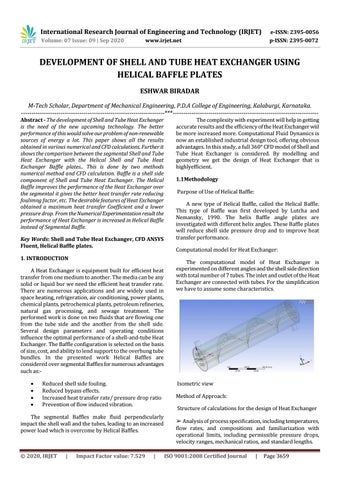
Isometric view Method of Approach: Structure of calculations for the design of Heat Exchanger ➢ Analysis of process specification, including temperatures, flow rates, and compositions and familiarization with operational limits, including permissible pressure drops, velocity ranges, mechanical ratios, and standard lengths. ISO 9001:2008 Certified Journal
|
Page 3659