International Research Journal of Engineering and Technology (IRJET)
e-ISSN: 2395-0056
Volume: 07 Issue: 08 | Aug 2020
p-ISSN: 2395-0072
www.irjet.net
Brake Biasing via Balance Bar Declination 1Tushar
1UG
Yadav
scholars, Medi-Caps University, Indore, M.P, India
---------------------------------------------------------------------***----------------------------------------------------------------------
brake caliper and brake rotor. To vary braking force on wheel one must need to vary cylinder bore, pad material, piston diameter of caliper or diameter of brake rotor but all these changes can’t be done easily. There comes the necessity of using brake bias generally known as balance bar. This balance bar allows us to make rapid adjustment according to track conditions, corners and driver preference [2].
Abstract - Braking System plays an essential role in
controlling the vehicle. Under the condition of braking, turning or accelerating, there is dynamic weight transfer of vehicle around its roll centre. Therefore, there is a need of accurate brake biasing for better handling of the vehicle. The main objective of this research paper is to derive the relation between the angle of declination of brake bias bar and biasing ratio. Brake biasing is an important characteristic that drivers want to adjust according to their needs. The brake biasing is done between two master cylinders to get the required proportion of force to master cylinders from one pedal via a balance bar. The derivation is done through the balancing of force and moment. The brake assembly is also explained in this paper for a proper understanding of how brake biasing is done. The result of this derivation is proved through the CAE analysis of brake assembly. With the use of the derived relation, one could achieve the required biasing ratio with proper assembly if there are least losses in assembly.
The biasing done through balance bar divide the pedal force of driver and the force is transmitted to master cylinder via pushrod. The accurate motion of pushrod is important to transfer the divided force of balance bar to master cylinder for its proper functioning. To transfer the force from balance bar without any loss of force, pushrod should travel in straight line without any buckling and pushrod should travel maximum in master cylinder.
1.1 System Layout
Key Words: Balance bar, Brake power, Push rod, Master Cylinder
1. INTRODUCTION Braking system is one of the most important part of vehicle subsystem. Function of a brake is to retard the speed of vehicle and hence, stop it completely. Brake involves frictional force to stop or control the vehicle. The perfect braking system will give desired deceleration according to drivers input to control the vehicle. The principle behind the brake is energy conversion, transforming kinetic energy into heat energy. This energy transformation occurs between brake disk and pads along with the clamping force applied by the brake caliper pads. Braking system plays an important part in vehicle in terms of safety and handling. The importance of dependable braking mechanism in any vehicle is paramount condition [1].
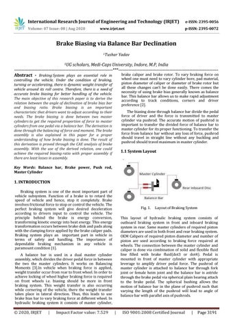
Fig. 1.
This layout of hydraulic braking system consists of outboard braking system in front and inboard braking system in rear. Same master cylinders of required piston diameters are used in both front and rear braking system. OEM Calipers of required piston diameter and number of piston are used according to braking force required at wheels. The connection between the master cylinder and caliper is done via combination of solid and flexible fluid line filled with brake fluid(dot3 or dot4). Pedal is mounted in front of master cylinder with appropriate leverage to amplify driver pedal force. The pushrod of master cylinder is attached to balance bar through fork joint or female heim joint and the balance bar is astride through the brake pedal via spherical plain bearing attach to the brake pedal. The spherical bushing allows the motion of balance bar in the plane of pushrod such that varying the length of the pushrod will lead to angle of balance bar with parallel axis of pushrods.
A balance bar is used in a dual master cylinder assembly, which divides the driver pedal force in between the two the master cylinders. It works on Balancing Moments [3].In vehicle when braking force is applied, weight transfer occur from rear to front wheel. In order to achieve locking of wheel higher braking force is required on front wheels i.e. biasing should be more in front braking system. This weight transfer is also occurring while cornering of the vehicle, there the weight transfer takes place in lateral direction. Thus, this leads to use brake bias bar to vary braking force at different wheel. In hydraulic braking system it consists of master cylinder,
Š 2020, IRJET
|
Impact Factor value: 7.529
Layout of Braking System
|
ISO 9001:2008 Certified Journal
|
Page 3191