International Research Journal of Engineering and Technology (IRJET)
e-ISSN: 2395-0056
Volume: 07 Issue: 03 | Mar 2020
p-ISSN: 2395-0072
www.irjet.net
Improved Energy Harvesting Conditioning Circuit using an Inductor Arjun Krishnappa Electrical and Computer Engineering, University of Dayton, Dayton, OH 45469 ---------------------------------------------------------------------***----------------------------------------------------------------------
Abstract - There are two techniques to increase the energy taken out from the piezoelectric transducer. One is based on the improvement of the piezoelectric transducer itself, and the other is based on an improvement of the circuit connected to the piezoelectric transducer. This paper uses the latter technique to propose a distinct method in order to reduce the ripples in energy conditioning circuit and to improve the efficiency and performance of the harvesting circuit.
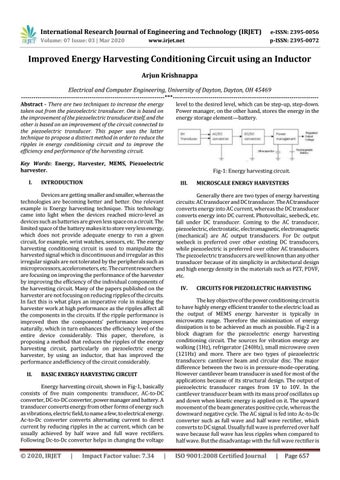
level to the desired level, which can be step-up, step-down. Power manager, on the other hand, stores the energy in the energy storage element—battery.
Key Words: Energy, Harvester, MEMS, Piezoelectric harvester. I.
Fig-1: Energy harvesting circuit.
INTRODUCTION
III.
Devices are getting smaller and smaller, whereas the technologies are becoming better and better. One relevant example is Energy harvesting technique. This technology came into light when the devices reached micro-level as devices such as batteries are given less space on a circuit. The limited space of the battery makes it to store very less energy, which does not provide adequate energy to run a given circuit, for example, wrist watches, sensors, etc. The energy harvesting conditioning circuit is used to manipulate the harvested signal which is discontinuous and irregular as this irregular signals are not tolerated by the peripherals such as microprocessors, accelerometers, etc. The current researchers are focusing on improving the performance of the harvester by improving the efficiency of the individual components of the harvesting circuit. Many of the papers published on the harvester are not focusing on reducing ripples of the circuits. In fact this is what plays an imperative role in making the harvester work at high performance as the ripples affect all the components in the circuits. If the ripple performance is improved then the components’ performance improves naturally, which in turn enhances the efficiency level of the entire device considerably. This paper, therefore, is proposing a method that reduces the ripples of the energy harvesting circuit, particularly on piezoelectric energy harvester, by using an inductor, that has improved the performance and efficiency of the circuit considerably. II.
Generally there are two types of energy harvesting circuits: AC transducer and DC transducer. The AC transducer converts energy into AC current, whereas the DC transducer converts energy into DC current. Photovoltaic, seebeck, etc. fall under DC transducer. Coming to the AC transducer, piezoelectric, electrostatic, electromagnetic, electromagnetic (mechanical) are AC output transducers. For Dc output seebeck is preferred over other existing DC transducers, while piezoelectric is preferred over other AC transducers. The piezoelectric transducers are well known than any other transducer because of its simplicity in architectural design and high energy density in the materials such as PZT, PDVF, etc. IV.
Energy harvesting circuit, shown in Fig-1, basically consists of five main components: transducer, AC-to-DC converter, DC-to-DC converter, power manager and battery. A transducer converts energy from other forms of energy such as vibrations, electric field, to name a few, to electrical energy. Ac-to-Dc converter converts alternating current to direct current by reducing ripples in the ac current, which can be usually achieved by half wave and full wave rectifiers. Following Dc-to-Dc converter helps in changing the voltage
|
Impact Factor value: 7.34
CIRCUITS FOR PIEZOELECTRIC HARVESTING
The key objective of the power conditioning circuit is to have highly energy efficient transfer to the electric load as the output of MEMS energy harvester is typically in microwatts range. Therefore the minimization of energy dissipation is to be achieved as much as possible. Fig-2 is a block diagram for the piezoelectric energy harvesting conditioning circuit. The sources for vibration energy are walking (1Hz), refrigerator (240Hz), small microwave oven (121Hz) and more. There are two types of piezoelectric transducers: cantilever beam and circular disc. The major difference between the two is in pressure-mode-operating. However cantilever beam transducer is used for most of the applications because of its structural design. The output of piezoelectric transducer ranges from 1V to 10V. In the cantilever transducer beam with its mass proof oscillates up and down when kinetic energy is applied on it. The upward movement of the beam generates positive cycle, whereas the downward negative cycle. The AC signal is fed into Ac-to-Dc converter such as full wave and half wave rectifier, which converts to DC signal. Usually full wave is preferred over half wave because full wave has less ripples when compared to half wave. But the disadvantage with the full wave rectifier is
BASIC ENERGY HARVESTING CIRCUIT
© 2020, IRJET
MICROSCALE ENERGY HARVESTERS
|
ISO 9001:2008 Certified Journal
|
Page 657