International Research Journal of Engineering and Technology (IRJET)
e-ISSN: 2395-0056
Volume: 07 Issue: 11 | Nov 2020
p-ISSN: 2395-0072
www.irjet.net
Model based Study on Effects of Valve Lifts and Events on the Performance of an Engine Anant Verma1, Prasad Bhosale2 1Student,
School of Mechanical Engineering, Vellore Institute of Technology, Chennai, India School of Mechanical Engineering, Vellore Institute of Technology, Chennai, India ---------------------------------------------------------------------***---------------------------------------------------------------------2Student,
Abstract - A conventional 4-stroke engine uses intake and
released in the combustion process to produce power. After the piston reaches to the BDC its time to drain the burnt air-fuel mix, and the exhaust valve is opened to pump out the exhaust gases with the piston moving upwards.
exhaust valves to control the flow of air into and out of the combustion chamber, these valves significantly dictate the amount of power that can be produced by a particular engine. Recently developed engines are integrated with modified cams to offer variable valve lifts and timings at different operating speeds in order to achieve optimum performance characteristics at all engine speeds. This paper seeks to provide an overview of obtaining valve profiles for any engine with the help of mathematical modelling, basic parameters used in the specification of valve timing, and its effects on engine performance. The objective of this paper is to study influences of intake and exhaust valves’ lifts, overlap, and timing w.r.t crank angle on the performance of a single-cylinder engine using a one-dimensional (1-D) model of KTM 390 engine which is developed virtually in GTPower and is used to simulate the engine performance over a rpm range with different valve profile inputs. Variables like volumetric efficiency and brake torque produced by the engine are taken into consideration to compare the performance.
The valve opening and closing events are crucial to produce power by burning the fuel. Intake valves can be considered as gates which allow fresh air-fuel mixture to enter into the combustion chamber and the variation in lifts, timing, and duration will affect the performance output of the engine; similarly, exhaust valves are the ones that are responsible for draining the burnt air fuel mixture from the combustion chamber to the ambient environment. Conventionally, these valves open and close with the help of camshafts that rotates at half the speed of the crankshaft and is connected to the crankshaft using belts or chains often known as timing belts. The cams are designed for specific valve lift profiles and define the opening and closing events of the valves. Duration is defined as the angle of the crankshaft rotation between the opening and the closing of the intake or the exhaust valve. At lower rpms (revolutions per minute) valve duration is more, whereas, at higher rpms duration is less. Hence, with the dynamic engine rpm the camshaft rpm and valveopen duration vary accordingly. [1,2]
Key Words: 1-D model simulation; Valve timing; Valve lift; Engine Performance; Single-cylinder Engine
1. INTRODUCTION
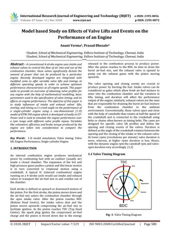
1.1 Valve Timing Diagram
An internal combustion engine produces mechanical power by combusting fuel with an oxidizer (usually air) inside a closed chamber. The expansion of the hot and high-pressure gases pushes a piston and this linear motion is in turn converted to rotational motion using a crankshaft. A typical IC (internal combustion) engine running on a 4-stroke cycle would use intake and exhaust valves to transport the air-fuel mix in and residue out of the chamber. Each stroke is defined as upward or downward motion of the piston. For the first stroke, the piston moves down and the air-fuel mix enters the combustion chamber through the open intake valve. After the piston reaches BDC (Bottom Dead Centre), the intake valves shut and the piston moves upwards compressing the air-fuel mix to facilitate ignition. As the piston reaches TDC (Top Dead Centre), the spark plug ignites the compressed air-fuel charge and the piston is forced down due to the energy
Š 2020, IRJET
|
Impact Factor value: 7.529
Fig -1: Valve Timing Diagram
|
ISO 9001:2008 Certified Journal
|
Page 580