International Research Journal of Engineering and Technology (IRJET)
e-ISSN: 2395-0056
Volume: 07 Issue: 11 | Nov 2020
p-ISSN: 2395-0072
www.irjet.net
Design and Analysis of a Gas Turbine Blade Abdul Qadir Talal1, Dr K Fazlur Rahman 2 1Abdul
Qadir Talal, Student, Dept of Mechanical Engineering, AITM Bhatkal, India K Fazlur Rahman, Head of department, Dept of Mechanical Engineering, AITM Bhatkal, India ---------------------------------------------------------------------***---------------------------------------------------------------------2Dr
Abstract – High pressure temperature (HPT) turbine blade
machinery. To protect blades from these high dynamic stresses, friction dampers are used.
Turbine blades are subjected to very strenuous environments inside a gas turbine. They face high temperatures, high stresses, and a potentially high vibration environment. All these factors can lead to blade failure, resulting in catastrophic failure of turbine.
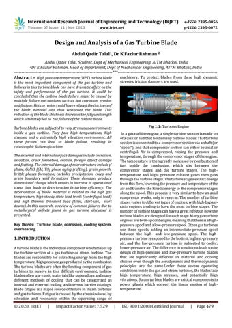
Fig 1.1: Turbojet Engine
is the most important component of the gas turbine and failures in this turbine blade can have dramatic effect on the safety and performance of the gas turbine. It could be concluded that the turbine blade failure might be caused by multiple failure mechanisms such as hot corrosion, erosion and fatigue. Hot corrosion could have reduced the thickness of the blade material and thus weakened the blade. This reduction of the blade thickness decreases the fatigue strength which ultimately led to the failure of the turbine blade.
In a gas turbine engine, a single turbine section is made up of a disk or hub that holds many turbine blades. That turbine section is connected to a compressor section via a shaft (or "spool"), and that compressor section can either be axial or centrifugal. Air is compressed, raising the pressure and temperature, through the compressor stages of the engine. The temperature is then greatly increased by combustion of fuel inside the combustor, which sits between the compressor stages and the turbine stages. The hightemperature and high- pressure exhaust gases then pass through the turbine stages. The turbine stages extract energy from this flow, lowering the pressure and temperature of the air and transfer the kinetic energy to the compressor stages along the spool. This process is very similar to how an axial compressor works, only in reverse. The number of turbine stages varies in different types of engines, with high-bypassratio engines tending to have the most turbine stages. The number of turbine stages can have a great effect on how the turbine blades are designed for each stage. Many gas turbine engines are twin-spool designs, meaning that there is a highpressure spool and a low-pressure spool. Other gas turbines use three spools, adding an intermediate-pressure spool between the high- and low-pressure spool. The highpressure turbine is exposed to the hottest, highest-pressure air, and the low-pressure turbine is subjected to cooler, lower-pressure air. The difference in conditions leads to the design of high-pressure and low-pressure turbine blades that are significantly different in material and cooling choices even though the aerodynamic and thermodynamic principles are the same.Under these severe operating conditions inside the gas and steam turbines, the blades face high temperature, high stresses, and potentially high vibrations. Steam turbine blades are critical components in power plants which convert the linear motion of hightemperature.
The external and internal surface damages include corrosion, oxidation, crack formation, erosion, foreign object damage and fretting. The internal damage of microstructure include γ’ phase, CoNi3 [(Al, Ti)] phase aging (rafting), grain growth, brittle phases formation, carbides precipitation, creep and grain boundary void formation. These damages produce dimensional change which results in increase in operational stress that leads to deterioration in turbine efficiency. The deterioration of blade material is related to the high gas temperature, high steady state load levels (centrifugal load) and high thermal transient load (trips, start-ups, start downs). In this research, a review of common failures due to metallurgical defects found in gas turbine discussed is presented. Key Words: Turbine blade, corrosion, cooling system, overheating
1. INTRODUCTION A turbine blade is the individual component which makes up the turbine section of a gas turbine or steam turbine. The blades are responsible for extracting energy from the high temperature, high pressure gas produced by the combustor. The turbine blades are often the limiting component of gas turbines to survive in this difficult environment, turbine blades often use exotic materials like superalloys and many different methods of cooling that can be categorized as internal and external cooling, and thermal barrier coatings. Blade fatigue is a major source of failure in steam turbines and gas turbines. Fatigue is caused by the stress induced by vibration and resonance within the operating range of
© 2020, IRJET
|
Impact Factor value: 7.529
|
ISO 9001:2008 Certified Journal
|
Page 479