International Research Journal of Engineering and Technology (IRJET)
e-ISSN: 2395-0056
Volume: 07 Issue: 11 | Nov 2020
p-ISSN: 2395-0072
www.irjet.net
Hardware of Nine Level MLI using Cascaded H-Bridge Bambhroliya Yashkumar1, Abhishek Movaliya2 1,2Student
department of Electrical Engineering Uka Tarsadia University Bardoli Gujarat 394601 ---------------------------------------------------------------------***----------------------------------------------------------------------
Abstract - Multilevel inverter technology has emerged recently as a very important alternative in the area of highpower medium-voltage energy control. This project presents the most important topologies like diode-clamped inverter
but increasing the number of levels needs more hardware, also the control will be more complicated. It is a trade-off between price, weight, complexity and a very good output voltage with lower THD.
(neutral-point clamped), capacitor-clamped (flying capacitor), and cascaded multilevel with separate dc sources. This project compares three different topologies of inverters (Diodeclamped inverter, flying capacitor clamped inverter and Cascaded H-bridge inverter). The switching pattern for inverters is explained as well. For each inverter, IGBTs and MOSFETs are used as switching devices to make the comparisons more accurate. The switches that are used for different inverters are the same for all of the inverters. If the THD is important, the 9-level inverters should be used, since it has a lower THD than the 5-level and the 7-level inverter. The 9-level multilevel inverters have the lowest THD when filters are not used. If the cost is important the two-level inverter should be used, since it has the lowest cost between all of the inverter topologies. The most important part is to decide which one is more important. This project is hardware model and simulation of 9-level MLI using Cascaded H-bridge inverter.)
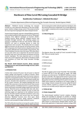
1.1 Block Diagram:
Fig 1.1 Block Diagram The diagram shows the model of 9 level cascaded h bridge MLI. There are mainly 5 parts: 1. DC supply 2. Inverter circuit 3. PWM technique
Key Words: Diode-clamped inverter, flying capacitor clamped inverter and Cascaded H-bridge inverter, IGBTs and MOSFETs
4. Control unit 5. Load
1. INTRODUCTION
The 48v Dc supply is given to the 9 level MLI. This 9-level MLI is convert 48V DC to the 48V peak Ac supply. The PWM technique use in the inverter. The MOSFET switches is control by micro-controller. The output of the inverter is given to the load. Inverters can be classified into single phase inverter and three phase inverters. Switching devices used in inverter uses PWM control signal for producing an AC output voltage. If input voltage remains constant the inverter called VSI and if current remains constant it is known as CSI. Three phase inverters are normally used for high power application.
A device that converts DC power into AC power at desired output voltage and frequency is called an Inverter. Phase controlled converters when operated in the inverter mode are called line commutated inverters. The power in the battery is in DC mode and the motor that drives the wheels usually uses AC power, therefore there should be a conversion from DC to AC by a power converter. The simplest topology that can be used for this conversion is the nine-level inverter that consists of sixteen switches. A multilevel inverter is a power electronic system which gives sinusoidal voltage output from several DC sources. These DC sources can be fuel cells, solar cells, ultracapacitors, etc. Since many switches are put in series the switching angles are important in the multilevel inverters because all of the switches should be switched in such a way that the output voltage and current have low harmonic distortion. Multilevel inverters have three types. Diode clamped multilevel inverters, flying capacitor multilevel inverters and cascaded H-bridge multilevel inverter.
2. TYPES OF MLI 3.1 Diode clamped MLI The diode-clamped multilevel inverter employs clamping diodes and cascaded dc capacitors to produce ac voltage waveforms with multiple levels. The inverter can be generally configured as a three, or five-level or seven level topologies, often known as neutral-point clamped (NPC) inverter, has found wide application in high-power medium-voltage (MV)
The THD will be decreased by increasing the number of levels. It is obvious that an output voltage with low THD is desirable,
Š 2020, IRJET
|
Impact Factor value: 7.529
|
ISO 9001:2008 Certified Journal
|
Page 265