International Research Journal of Engineering and Technology (IRJET)
e-ISSN: 2395-0056
Volume: 07 Issue: 11 | Nov 2020
p-ISSN: 2395-0072
www.irjet.net
Design and Analysis of 3-Way Power Divider for UWB Applications Shruti Patankar1, Md. Suhel2 1M.Tech
Student, Dept. of Elec. & Comm. Engg., SRIST JBP, M.P., India Professor, Dept. of EC, SRIST JBP, M.P., India ---------------------------------------------------------------------***---------------------------------------------------------------------2Assistant
Abstract- The proposed Wilkinson power divider has been designed and printed on low-cost Epoxy laminate substrate FR4 along with the thickness of 1.6mm and relative permittivity of ɛr =4.3 respectively. The transformation of power divider network which are based on bent corners as a replacement of sharp corners or edges used for the decrement in unintended radiation and employing a single radial stub on each branch to encounter the antenna-specifications. Further some adjustments in the dimension of stubs matching in order to increase the reflection of the power divider network. The design presents the model of a power divider and maintains an equal power splitting at different ports with practical insertion loss and conventional return loss below -10dB. The reasonable impedance matching has achieved at every single port with acceptable isolation performance values over the (3to-10 GHz) frequency range. The divider as well as antenna elements design and its optimization are practicable via computer simulation technology (CST) simulation software. The experimental results are revealed to encounter the arrayspecifications under ultra-wideband frequency range.
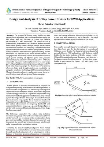
losses and compacted in size. Although, the isolation circuit is associated with output ports and it also offers electrical separation but cannot physical isolation to the circuit. 2. CONVENTIONAL DESIGN Two parallel uncoupled quarter wavelength transmissionlines have been used for the formation of conventional Wilkinson power divider. The characteristic impedance of all uncoupled lines is √2Z0 and matched with the input port of divider. For the better isolation of divider a shunt resistor 2Z0 would be associated among the output ends of the port. The basic structural configuration of 1 to 2 sections power divider is represented in Figure 1(a) and Figure 1(b) correspondingly.
Key Words: UWB, Array, simulation, power, gain 1. INTRODUCTION Power Splitter or Divider is considered as a significant component especially in microwave circuit design as well as interconnected subsystems. It is extensively used in power amplifiers, mixers and phase shifters. At this time the power divider strongly considers as a significant component mainly in an ultra-wide band application and antenna array related system feeding network. The design model of Wilkinson power divider is very popular due to its narrow bandwidth and particularly used in UWB antenna array application. For the further advancement in frequency bandwidth and expansion in channel frequency a general design of power divider with some modification in basic geometrical shape has been developed.
Fig 2(a): Equally-Split 2-way Wilkinson Power Divider
The following parameters like return loss, isolation, insertion loss, group delay and bandwidth achieved from divider network has necessary for the configuration of any power divider and the mentioned parameters generally used to evaluate the specific performance in many satellite and radar communication application system. Currently, the most focused type of power divide named Wilkinson is an optimal selection of several researchers. It is typically used in feeding network of antenna array system because of its simple geometrical structure, low insertion © 2020, IRJET
|
Impact Factor value: 7.529
|
Fig 2(b): Equivalent Circuit of Conventional Power Divider Network
ISO 9001:2008 Certified Journal
|
Page 250