International Research Journal of Engineering and Technology (IRJET)
e-ISSN: 2395-0056
Volume: 07 Issue: 11 | Nov 2020
p-ISSN: 2395-0072
www.irjet.net
Cutting Response of Single Point Cutting Tool using FEA Judhisti 1 and Ram Krishna Rathore2 1M.Tech
scholar, Rungta College of Engineering & Technology, Bhilai, Chhattisgarh, India Professor, Rungta College of Engineering & Technology, Bhilai, Chhattisgarh, India ---------------------------------------------------------------------***---------------------------------------------------------------------2Assistant
Abstract - In machining process, the geometry of cutting
tool is one of the major parameter on impacting the quality of manufacturing process of a component. The tool geometry consists of various cutting angles and faces which have significant role in Machining different surfaces and components. With the advancement in computer technology, FEA gives an opportunity to have a detailed examination of all cutting tool angles and faces on the finish component (workpiece). In this paper a single point cutting tool is modeled in Solid-works software and then the model is imported in ANSYS 18.1, where analysis has been carried put. By subjecting the real boundary condition to cutting tool geometrical parameter on stress and tool deformation has been examined.
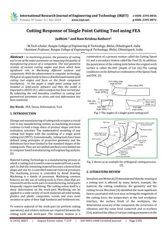
combination of a primary motion called the Cutting Speed (v) and a secondary motion called the Feed (f). In addition, the penetration of the cutting tools below the original work surface is called the DOC (Depth of Cut (d)) The cutting conditions can be defined as combination of the Speed, Feed, and DOC. [2]
Key Words: FEA, Stress, Deformation, Tool. Fig. 1 The angles of a single-point cutting tool.
1. INTRODUCTION (Design and manufacturing of cutting tools occupies a crucial role in any manufacturing system, as machining processes continue to hold a large share of product shape and form realization activities. The mathematical modeling of any cutting tool begins with the modeling of a single point cutting tool (SPCT). Conventionally, cutting tools have been defined using principles of projective geometry and the definitions have been limited to few standard shapes of the cutting tools. They are not unified and find a very limited use in computer based manufacturing and engineering analysis. [1] Material Cutting Technology is a manufacturing process in which a cutting tool is used to remove material from a workpart. So that the remaining material becomes a desired final shape and size by a controlled material-removal processes. The machining process is controlled by detail drawing. Machining is a family of processes. Machining common features are the use of cutting tools to form chips that are removed from the work-part. In manufacturing, metal parts frequently require machining. The cutting action itself is a shear deformation on the work-part. Machining can be applied to a wide variety of work materials all solid metals, plastics and plastic composites, woods and even most ceramics in spite of their high hardness and brittleness etc. To remove material of the work-part (to perform cutting operations) and relative motions are required between the cutting tools and work-part. The relative motion is a Š 2020, IRJET
|
Impact Factor value: 7.529
|
Fig. 2 shows as an example for orthogonal cutting process. [2]
2. LITERATURE REVIEW Sewailem and Mobarak [3] demonstrated that the wearing of a cutting tool is affected by many factors, example, the material, the cutting conditions, the geometry and the cutting forces. Merchant [4] identified the most significant factors associated with tool wear as being the magnitude of the cutting force, the temperature at the tool workpiece interface, the surface finish of the workpiece, the dimensional accuracy of the component, the occurrence of vibration, and the noise level. Luttervelt and co-workers [5,6] analyzed the effect of various cutting parameters on the ISO 9001:2008 Certified Journal
|
Page 1195