International Research Journal of Engineering and Technology (IRJET)
e-ISSN: 2395-0056
Volume: 07 Issue: 11 | Nov 2020
p-ISSN: 2395-0072
www.irjet.net
New Design Formulae for Equilateral Triangular Microstrip Antenna Satish Kumar Bhatnagar Professor, Dept. of Electronics and Communication Engineering, Swami Keshvanand Institute of Technology, Management and Gramothan, Jaipur, Rajasthan, India
-----------------------------------------------------------------------------***---------------------------------------------------------------------------1.2 The Classical Models account the effect of fringing fields on the sidelength of an For microstrip antenna, equilateral triangular patch has equilateral triangular microstrip antenna (ETMSA). The been widely investigated and used. Either moment method model is straight forward, simple and accurate. It is propounded that the extension in physical sidelength of or cavity model has been generally used. These covered a ETMSA is directly proportional to the physical sidelength range of substrate dielectric constants (r) and substrate itself and also to the normalized thickness of the dielectric thicknesses (h). The cavity model assumes electric walls substrate. At present several formulae are in use for this. on the top and bottom, and a magnetic wall around the The new model gives equally good results without any sides. To take into account the effect of fringing fields, iteration. Novel results are that for all ETMSA (1) the ratio either effective side length or effective dielectric constant of extension in physical sidelength to physical sidelength itself is equal to H (2) the ratio of enlarged area to physical or both have been used with convenience for explaining area of the patch is (1+2H) (3) the ratio of extension in the measured results of resonance frequency and other physical sidelength to the height of the substrate is a parameters. Dynamic permittivity has also been constant 2/3 (4) a graphical tool for determining the considered for the same reason. When an effective physical sidelength of ETMSA has been put forward. Here H dielectric constant (eff) is used the user has first to is the normalized substrate thickness. The results compare determine eff then only he can estimate the physical very well with the published measured and calculated data. Large number of ETMSA have been designed and simulated sidelength. Formula for eff is based on rectangular to validate the new thinking. Some typical data and geometry of the patch. This formula uses a value of W simulation results have been incorporated in this paper. The (length of non-radiating side of the rectangular patch) that work reported here is very useful for the antenna designer is discarded later on. If a triangular microstrip antenna (as as the required value of Sp can be quickly and accurately shown in Fig-1)of side length S is constructed over an found. The results are of great significance as these point to insulating substrate whose dielectric constant is r then, the similarities between MSA of various shapes. using cavity model with perfect magnetic walls it can be Key Words: — Bhatnagar’s Postulate, Design, Fringing shown that [1] Fields, Guide Wavelength, Physical Dimensions, Resonant frequency, Triangular Microstrip Antenna, (1)
Abstract - This paper presents a model for taking into
√
1. INTRODUCTION 1.1 User Requirement A microstrip antenna designer wants to know quickly and accurately the physical dimensions of the patch for his desired resonant frequency. The resonant frequency (fr) depends on the electrical dimensions that are slightly larger than the physical dimensions due to fringing field effect. Vastly different models have been proposed and are in use for this. Resonant frequency values obtained from these formulae and also from simulation differ from one another as well as from physically measured values because of several assumptions that may not be true in every case.
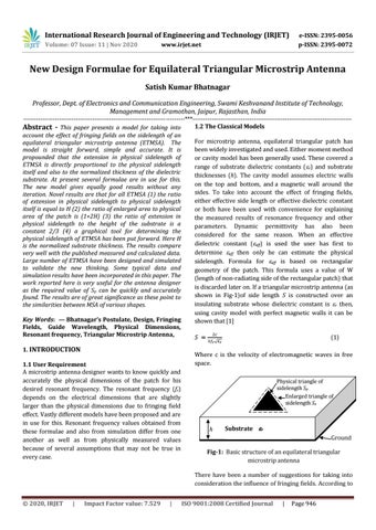
Where c is the velocity of electromagnetic waves in free space. Physical triangle of sidelength Sp Enlarged triangle of sidelength Se
Se Sp
h
Substrate r Ground
Fig-1: Basic structure of an equilateral triangular microstrip antenna There have been a number of suggestions for taking into consideration the influence of fringing fields. According to
© 2020, IRJET
|
Impact Factor value: 7.529
|
ISO 9001:2008 Certified Journal
|
Page 946