International Research Journal of Engineering and Technology (IRJET)
e-ISSN: 2395-0056
Volume: 07 Issue: 10 | Oct 2020
p-ISSN: 2395-0072
www.irjet.net
Review on Building a Cost Efficient Pen Plotter Jayananden M1 1Student,
Dept. of Mechatronics Engineering, Kumaraguru College of Technology, Tamil Nadu, India ---------------------------------------------------------------------***----------------------------------------------------------------------
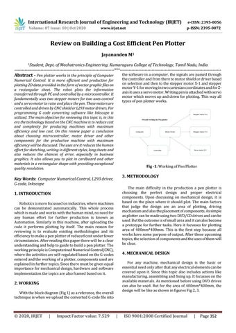
the software in a computer, the signals are passed through the controller and from there to motor shield or driver based on selection and then to the stepper motor X-1 and stepper motor Y-1 for moving in two cartesian coordinates and for Zaxis it uses a servo motor. Writing pen is attached with servo motor which moves up and down for plotting. This way all types of pen plotter works.
Abstract - Pen plotter works in the principle of Computer
Numerical Control. It is more efficient and productive for plotting 2D data provided in the form of vector graphic files on a rectangular sheet. The robot plots the information transferred through PC and controlled by a microcontroller. It fundamentally uses two stepper motors for two axes control and a servo motor to raise and place the pen. These motors are controlled and driven by CNC shield or L293 motor drivers. For programming G code converting software like Inkscape is utilized. The main objective for reviewing this topic is, in this era the technology based on the CNC machine is to reduce cost and complexity for producing machines with maximum efficiency and low cost. On this review paper a conclusion about choosing microcontroller, motor driver and other components for the productive machine with maximum efficiency will be discussed. The uses are it reduces the human effort for sketching, writing in different styles, long sheets and also reduces the chances of error, especially in business graphics. It also allows you to plot in cardboard and other materials in a rectangular shape with providing exceptional quality resolution.
Fig -1: Working of Pen Plotter
3. METHODOLOGY
Key Words: Computer Numerical Control, L293 driver, G code, Inkscape
The main difficulty in the production a pen plotter is choosing the perfect design and proper electrical components. Upon discussing on mechanical design, it is based on the place where it should plot. The main factors that judge the design are an area of plotting, driving mechanism and also the placement of components. As simple as plotter can be made using two DVD/CD drives and can be used. But the outcome is of small area and it can also become a prototype for further tasks. Here it focusses for plotting area of 400mm*400mm. This is the first step because all works have some purpose of output. After these upcoming topics, the selection of components and the uses of them will be clear.
1. INTRODUCTION Robotics is more focussed on industries, where machines can be demonstrated automatically. This whole process which is made and works with the human mind, no need for any human effort for further production is known as Automation. Similarly in this machine, after uploading the code it performs plotting by itself. The main reason for reviewing is to evaluate existing methodologies and its efficiency to make a pen plotter of reduced cost under fewer circumstances. After reading this paper there will be a clear understanding and help to guide to build a pen plotter. The working principle is Computerized Numerical Control(CNC), where the activities are self-regulated based on the G-codes entered and the working of a plotter, components used are explained in further topics. Since there must be given equal importance for mechanical design, hardware and software implementation the topics are also framed based on it.
4. MECHANICAL DESIGN For any machine, mechanical design is the basic or essential need only after that any electrical elements can be covered upon it. Since this topic also includes actions like manufacturing, assembling and fixing up. It focusses on the available materials. As mentioned before using DVD drives can also be used. But for the area of 400mm*400mm, the design will be like as shown in figures Fig 2, 3.
2. WORKING With the block diagram (Fig 1) as a reference, the overall technique is when we upload the converted G-code file into
Š 2020, IRJET
|
Impact Factor value: 7.529
|
ISO 9001:2008 Certified Journal
|
Page 352