International Research Journal of Engineering and Technology (IRJET)
e-ISSN: 2395-0056
Volume: 07 Issue: 10 | Oct 2020
p-ISSN: 2395-0072
www.irjet.net
Speed Control of Asymmetrical Six Phase Induction Motor based Fuzzy Logic Controller Mr. Myasar Salim Alattar 1, Dr. Ahmed Nasser Alsammak2 1Assistance
Professor, Dept. of Mechatronics Engineering, University of Mosul, Mosul-Iraq. 2Assistance Lecturer, Dept. of y, University of Mosul, Mosul-Iraq. ---------------------------------------------------------------------***----------------------------------------------------------------------
Abstract - ac electric drives for both synchronous and
artificial neural network depends on volume of training data. Anfis controller represent a combination both last schemes with their properties.
induction take great interests by researchers and industrialist especially last type due to there is effortlessness for speed regulation, ruggedness, and high power to weight ratio etc…three phase drives was the conventional types that covered wide range of industrial and transmitting application .but with rising power demand and development in power electronics device and control schemes conventional induction motor drives could not be able to overcome all requirements in different fields , that’s leads to think to create an other types of drivers having more than three phase ( five, six ,seven and nine etc. ) .six phase induction motor drive become one of these type used for many application instead of three phase type rising systems dependability, efficiency and flexibility in control process . [1]
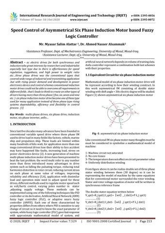
1.1 Equivalent Circuit for six phase induction motor Mathematical model of six phase induction motor drive will be represent according to how their winding construct. In this work asymmetrical IM consisting of double stator winding with shift angle = 30o electric degree will be studied. Figure (1) shown asymmetrical six phase induction motor
Key Words: multi-phase drives, six phase drive, induction motor, six phase inverter, anfis…
1. INTRODUCTION Since last five decades many advances have been founded in conventional variable speed drive where three phase IM used to drive load in many fields like factory, vehicle, marine ship and propulsion ship. These loads are limited within many hundreds of kilo watt, for application more than one mega conventional drives lose their ability to face accident may have happened like faults, increasing load, stress on power electronics device [2]. A new generation of machine multi-phase induction motor drives have been presented to beat the last problem. the word multi refer to any number more than three introduced many advantages in drive system such as falling the pulsating torque, reducing total harmonics distortion in rotor circuit, reducing current stress on each phase at same value of voltages, improving reliability and efficiency [3,4], application with dissimilar load and operation state need to adjust speed for these drives, different methods used to regulate motor speed such as volt/hertz control, varying poles number in stator ,adjusting supply voltage. These methods can be implemented using one of the following techniques like PID controller or its derivative, Artificial Neural Network (ANN) fuzzy logic controller (FLC), or adaptive neuro fuzzy controller (ANFIS). Each one of them characterized by properties differs from others where PID is sensitive to any change of circuit so it need to know the exact parameter of system, while fuzzy logic controller (FLC) gave fast response with approximate mathematical model of system, and
© 2020, IRJET
|
Impact Factor value: 7.529
Fig -1: asymmetrical six phase induction motor Like conventional IM six phase motor many thoughts must be must be considered to symbolize a mathematical model of machine: 1- Machine circuit not saturated 2- No core losses 3- The temperature does not effect on circuit parameter value 4- Uniformly distribution winding From figure above it can be realize double set of three phase stator winding between them (30 degree) so it can be representing the model of machine by the same equations that for conventional motor surrounded the rotor winding. Stator and rotor voltage equation of motor will be written in synchronous reference frame The double stator equation written below V_qst1=R_(qst1) I_qst1+〖wλ〗_ ( dst1)+P λ_( qst1) .…………... (1) V_dst1=R_(dst1) I_dst1-〖wλ〗_( qst1)+P λ_( dst1) ……………. (2) V_dst2=R_(dst2) I_dst2+〖wλ〗_( qst2)+P λ_( dst2) ……………. (3)
|
ISO 9001:2008 Certified Journal
|
Page 213