International Research Journal of Engineering and Technology (IRJET) Volume: 07 Issue: 10 | Oct 2020 www.irjet.net
e-ISSN: 2395-0056 p-ISSN: 2395-0072
DESIGN AND FABRICATION OF SYSTEM FOR SMALL SCALE POWER GENERATION USING SPEED BRAKER Babin Dangal1, Subash Pradhan2, Aashish Giri3, Shiva Shanker Pandey4, Shusam Bhujel5 Aditya Bimal6 1,2,3,4,5Students,
Tribhuvan University, Institute of Engineering(IOE), Purwanchal Campus, Dharan, Nepal Department of Mechanical Engineering, Tribhuvan University, Institute of Engineering(IOE), Purwanchal Campus, Dharan, Nepal ------------------------------------------------------------------------***------------------------------------------------------------------------2. METHOD AND MATERIAL Abstract: With the increasing exhausts of fossils fuels 6Lecturer,
and its adverse environmental effects, clean energy production has become a quintessential demand of the hour. In the other hand, a huge amount of kinetic energy is wasted on our roads which can be used for clean energy production and various other purposes. This paper presents the design of components like spring, rack and pinion and Shaft to make the speed breaker able to handle the load of max 400 kg along with the experimental study which shows that the power to 1.2 to 28.6 watt was produced when the load of 60 to 240kg were applied at a different interval. Hence, we concluded that this method could be a good source of a non-conventional form of producing energy.
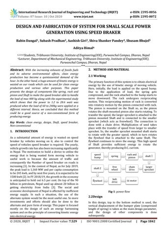
2.1 Working The primary function of this system is to obtain electrical energy by the use of kinetic energy of moving vehicle. Here, initially, the load is applied on the speed hump. Due to the application of load, the spring gets compressed, and the rack attached to the hump starts to move downward. The rack undergoes reciprocating motion. This reciprocating motion of rack is converted into rotatory motion by the pinion connected with rack. The pinion is mounted on the Shaft so, as the pinion rotates the shaft-mounted pinion also starts rotating. To transfer the speed, the larger sprocket is attached to the pinion mounted Shaft and is connected to the smaller sprocket (which acts as freewheel). The connection is done with a chain drive. Multiplication of seed takes place with the transfer of speed from larger to smaller sprocket. So, the smaller sprocket mounted shaft starts to rotate with the greater speed, which in turn rotates the flywheel that is attached to the same Shaft. The flywheel continues to store the energy. This high speed of Shaft provides sufficient energy to rotate the generator, thereby producing D.C. current.
Key Words: clean energy, design, Shaft, speed breaker, Non-conventional
1. INTRODUCTION As a substantial amount of energy is wasted on speed breaker by vehicles moving on it, also to control the speed of vehicles speed breaker is required. The yearly, vehicle growth rate has also been increasing significantly in Nepal. The motivation to build a device to utilize the energy that is being wasted form moving vehicle to useful work is because the amount of traffic and consequently the Number of speed breaker on roads is increasing [1]. In the context of Nepal, as for July 2019, the peak load is 1,160 MW and per capita consumption to be 245 kwh, and by next five years, it is expected to be 1500 kwh [2]. In FY 2018/19, the growth in the economy is anticipated to hold out 6.5 per cent. On top of the 90 billion in petroleum, Nepal used up almost 20 billion in getting electricity from India [3]. The social and economic development of Nepal is affected by inefficient energy supply. In such a situation, the use of the alternate system would be the most useful one. So more investments and efforts should also be done to the alternate and pure form of energy. This paper is focused mostly on the design of such an energy harnessing system and on the principle of converting kinetic energy into electrical energy.
Š 2020, IRJET
|
Impact Factor value: 7.529
speed hump
spring
rack and pinion
shaft 1
shaft 2
free wheel
chain drive
larger sprocket
flywheel
belt drive
dc motor
Fig-1: power flow
2.2Design In this design, top to the bottom method is used, the vertical displacement of the bumper plate (compressed length of spring) is taken as the main design parameter, and the design of other components is done subsequently.
|
ISO 9001:2008 Certified Journal
|
Page 1842