International Research Journal of Engineering and Technology (IRJET)
e-ISSN: 2395-0056
Volume: 06 Issue: 03 | Mar 2019
p-ISSN: 2395-0072
www.irjet.net
Microstrip patch antenna for C band satellite application Akshay kumar1, Logeshwaran2, Arun3 1,2PG
scholar, Anna university regional campus, Madurai, India. Professor, Electronics and communication Engineering, Anna university regional campus, Madurai, India. ----------------------------------------------------------------------***--------------------------------------------------------------------3Assistant
Abstract - This paper is proposes about microstrip patch antenna in satellite application. The frequency bandwidth of this antenna is 0.3GHz and its return loss is -24.33dB. This antenna has uplink frequency of 5.9GHz and downlink frequency of 5.1GHz. The design of the patch antenna is calculate, simulated and optimized by HFSS software. In military application this c band satellite antenna is mainly focused over the voice as well as data communication. The favorable frequency of this antenna is 4-8GHz and it can be illustrated in various dimension and used for satellite.
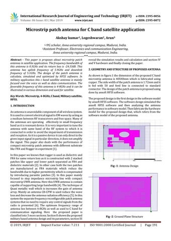
reveal the simulation results and calculation and section IV and V hardware and finally closing the paper. 2. GEOMETRY AND STRUCTURE OF PROPOSED ANTENNA As shown in figure.1 the dimension of the proposed C band microstrip antenna is 40X40mm which is fabricated using copper. The side width of the patch antenna is 1.72mm and it is fed with 50 and feed line is connected to standard connector. The design of the patch antenna is proposed using done by ansoft HFSS software.
Key Words: Microstrip, 4-8GHz, C band, Military satellite, HFSS.
The proposed design is the first design in the software model by ansoft HFSS software. The software design simulated the ansoft HFSS software and then analyzing the antenna performance in software model. Then fabricate the hardware model for the proposed design that, which refers from the software model of the proposed antenna.
1. INTRODUCTION An antenna is unavoidable component of all wireless system. It is used to convert electrical signal to EM waves by acting as a medium between RF transceivers and free space. Many of the antennas are operating effectively in small frequency band as it is resonant device. It is very important to tune the antenna with same band of the RF system to which it is connected in order to avoid the impairment of transmission and reception. As it is a passive device it can only direct to the given input signal in particular direction, it does not amplify the signal. This paper also deals with the performance of compact microstrip patch antenna with different substrate like FR4 and Rogger in experiment [1]. In this paper we knows that rogger is used as dielectric and FR4 for same return loss as it is constructed with 2 stacked patches like upper and lower patch separated as FR4 and dielectric materials [2]. In other case both the two patches are manufactured as FR4 materials which reduce the bandwidth due to higher permittivity which is compensated by introducing parasitic patches [3]. In this paper mainly focused to step impedance microstrip line with compact microstrip UWB antenna. Here this UWB antenna is contain capable of supporting large bandwidth [4]. The technique of Quasi metallic wall which is increases the gain of antenna array. Mainly an antenna CB-CPW is used reduce the wave loss and decrease the antenna radiation efficiency [5]. In this system the separate frequency reconfigurable patch antenna systems that no need to require any control signals from the radio is presented [6]. The optimum frequency range of antenna lies between 4-8GHz as well as used to C band for communication signaling. Here the proposed paper is classified into 3 more sections. Section II shown the proposed military based antenna design and its parameters, section III
Š 2019, IRJET
|
Impact Factor value: 7.211
Fig -1: Antenna Design
Fig -2: Ground Plane Structure
|
ISO 9001:2008 Certified Journal
|
Page 191