International Research Journal of Engineering and Technology (IRJET)
e-ISSN: 2395-0056
Volume: 06 Issue: 03 | Mar 2019
p-ISSN: 2395-0072
www.irjet.net
dsPIC Based Implementation of Sinusoidal Pulse Width Modulation Techninques for Multilevel Inverters M. A. Waghmare1; K. A. Onkar2; A. V. Jadhav3 1Department
of Electrical Engineering; VNIT; Nagpur 440013; India of Electrical Engineering; St. Vincent Palloti College of Engineering and Technology; Nagpur 441108; India 3Department of Electrical Engineering; KDK College of Engineering; Nagpur 440009; India ---------------------------------------------------------------------***--------------------------------------------------------------------Abstract— The simplicity of multi-carrier pulse width 2Department
modulation makes it a powerful gating scheme to switch the multilevel inverters (MLI’s) and also it helps in realization of various MLI topologies. In this paper the generation of switching pulses by various SPWM techniques for MLI has been presented by using single carrier generated in microcontroller. The schemes is implemented on five-level cascaded H-bridge (CHB) and THD has been computed. The simulation and practical results are presented to show the reliability of the implementation.
Vdc Vdc
Vdc
(a)
Vo/p Vdc
Vo/p
+ -
(b)
(c)
To control the output voltage of MLI various modulation techniques are used such as multicarrier PWM (MCPWM), Space vector PWM, Selective harmonic PWM [4-6]. Among the mentioned PWM techniques MCPWM is most commonly used method for switching of MLI because of its ease of applicability and implementation in various topologies. On the basis of carrier MCPWM can be classified as (i) phase shifted PWM (PS-PWM) and (ii) level shifted PWM (LS-PWM). The LS-PWM can be classified further into phase disposition (PD-PWM), phase disposition (PD-PWM), phase opposition and disposition PWM (POD-PWM), alternate phase opposition and disposition PWM (APOD-PWM), and inverted phase disposition (IPDPWM)
MLI consists of a particular number of power semiconductor switches according to number of levels and number of voltage sources or may have number of capacitor voltage sources which forms power circuit of the MLI and generates stepped voltage waveforms. The gating pulses switch ON the switches and conducts the inverter which gives higher voltage level at output, and switches will have less voltage stress across them.
All the above mentioned schemes can be implemented by using analog circuit using op-amp and RC-network, but this will makes the gating circuit cumbersome and complex for higher level of inverters. Then for digital implementation of PWM schemes microcontroller is used. But microcontrollers are specially designed to control the two-level inverters because of limited PWM modules, input-output pins present within it and along with that microcontrollers have to perform functions like signal detection and control algorithm. For switching the multilevel
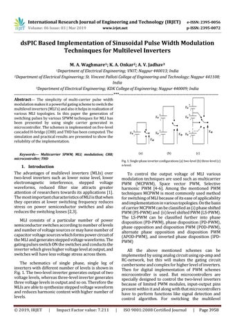
The schematics of single phase, single leg of inverters with different number of levels is shown in Fig. 1. The two-level inverter generates output of two voltage levels, whereas three-level inverter generates three voltage levels in output and so on. Therefore the MLIs are able to synthesize stepped voltage waveform and reduces harmonic content with higher number of levels. Impact Factor value: 7.211
+ -
-
Fig. 1. Single-phase inverter configurations (a) two-level (b) three-level (c) n-level.
1. Introduction The advantages of multilevel inverters (MLIs) over two-level inverters such as lower noise level, lower electromagnetic interference, stepped voltage waveforms, reduced filter size attracts greater attention of researchers towards its applications [1]. The most important characteristics of MLI is that when they operates at lower switching frequency reduces stress on power semiconductor switches and also reduces the switching losses [2,3].
|
Vdc
Vdc
-
+
Vo/p
Keywords— Multicarrier SPWM; MLI; modulation; CHB; microcontroller; THD
© 2019, IRJET
+ -
+
+
|
ISO 9001:2008 Certified Journal
|
Page 3958