International Research Journal of Engineering and Technology (IRJET)
e-ISSN: 2395-0056
Volume: 05 Issue: 06 | June-2018
p-ISSN: 2395-0072
www.irjet.net
DESIGN AND IMPLEMENTATION OF THREE PHASE GRID SIMULATOR Dr.Mathew K1, Chaithra K S2 1HOD
ECE Department, Mar Athanasius College of Engineering, Kothamangalam, Kerala, India ECE Dept., Mar Athanasius College of Engineering, Kothamangalam, Kerala, India ---------------------------------------------------------------------***--------------------------------------------------------------------2M-Tech
Abstract - When Grid-connected systems are used they
of the inverter rather than the issues related to the grid simulator. In [3], there is a mention of a 250kVA grid simulator that is used to generate sag, swell and harmonic issues to test distributed generation systems. However, very little technical detail is available. In [4], laboratory grid simulator based on three-phase four-leg inverter is implemented. Employing the dual-loop control with capacitor current feedback and output voltage feed forward, the grid simulator output voltage could be precisely regulated at both steady state and dynamic development of FPGA. With the development of FPGA it is possible to use short sampling times for predictive control algorithms, being feasible the use of sampling time in a real system.
should experience scenarios like voltage sag, voltage swell, frequency variations, voltage unbalance etc. So it is necessary to test these systems under laboratory, then these scenarios do not exist and an almost stiff voltage source is obtained. But, in order to qualify the grid-connected systems, it becomes essential to test them under various grid disturbances which are mentioned earlier. The grid simulator is a hardware set up that can be programmed to generate typical conditions experienced by the grid-connected systems. It is basically an inverter that is controlled to act like a voltage source in series with a grid impedance. This paper describes the design and implementation of a three phase grid simulator. Control signal for the inverter module is given using Spartan 6 FPGA board with software implemented on Xilinx using Verilog code. Visual studio is implemented here in order to implement graphical user interface.
Here in this paper mainly focus on the implementation of grid simulator using FPGA.
2. METHODOLOGY
Key Words: Grid simulator, Three phase inverter,
Grid simulator is used to simulate,test and prove the system performance.To emulate the grid faults high dynamic performance is essential to control the output voltage of simulator is necessary. As an example, during voltage faults ,the grid voltage may fall a millisecond range.In order to analse such faults a hardware want to be implemented.
Spartan 6 FPGA board, Visual studio
1. INTRODUCTION With the increasing penetration of distributed generation (DG) and large-scale renewable energy systems like wind turbines or solar cells, more stringent grid codes have been issued to prescribe how those grid-connected systems to support the network during grid disturbances. For further development of grid-connected systems according to new grid codes and correlative standards, a hardware set up is necessary. Such a hardware set up is termed as grid simulator. Grid simulator is essential to design, test, analyze and verify the performance and characteristics of various grid-connected devices under different grid conditions in a laboratory [1].
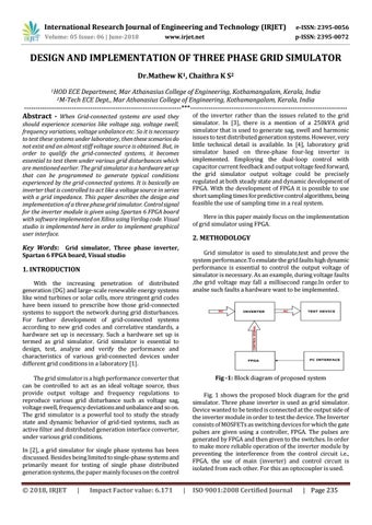
Fig -1: Block diagram of proposed system
The grid simulator is a high performance converter that can be controlled to act as an ideal voltage source, thus provide output voltage and frequency regulations to reproduce various grid disturbance such as voltage sag, voltage swell, frequency deviations and unbalance and so on. The grid simulator is a powerful tool to study the steady state and dynamic behavior of grid-tied systems, such as active filter and distributed generation interface converter, under various grid conditions.
Fig. 1 shows the proposed block diagram for the grid simulator. Three phase inverter is used as grid simulator. Device wanted to be tested is connected at the output side of the inverter module in order to test the device. The Inverter consists of MOSFETs as switching devices for which the gate pulses are given using a controller, FPGA. The pulses are generated by FPGA and then given to the switches. In order to make more reliable operation of the inverter module by preventing the interference from the control circuit i.e., FPGA, the use of main (inverter) and control circuit is isolated from each other. For this an optocoupler is used.
In [2], a grid simulator for single phase systems has been discussed. Besides being limited to single-phase systems and primarily meant for testing of single phase distributed generation systems, the paper mainly focuses on the control
Š 2018, IRJET
|
Impact Factor value: 6.171
|
ISO 9001:2008 Certified Journal
| Page 235