International Research Journal of Engineering and Technology (IRJET)
e-ISSN: 2395-0056
Volume: 05 Issue: 03 | Mar-2018
p-ISSN: 2395-0072
www.irjet.net
Warp Beam Carrier for Power Looms V. Praveen1, K. Rajkumar2, Mr. R. Rajiev3 1,2UG student of Bannari Amman Institute of Technology, Sathyamangalam Professor(Sr.G), Dept. of Mechanical Engineering, Bannari Amman institute of technology, Sathyamangalam, Tamilnadu, India ---------------------------------------------------------------------***--------------------------------------------------------------------3Assistant
Abstract - For the past years textile industry has a better
development. But it has less material handling equipments. Till now the large weighted beams are lifted and transmitted only by human hands. To overcome the problem, we have decided to fabricate a carrier for warp beam which is large beam that has to be changed often . Our main objective is to reduce manual work, increase easy material handling .Our project consists of hydraulic pump, hydraulic jack, steel frames. A Warp Beam carrier is a device used for lifting or lowering a warp beam by means of a hydraulic cylinder with the chain. It may be manually operated, electrically or pneumatically driven. The warp beam is attached to the lifting hook. The range of lifting machines can be applied across all industry sectors.
1. INTRODUCTION The Warp Beam is a iron rod in which the thread required for power loom to make cloth. The rod when empty weighs up to 30 kg. If it is loaded weighs up to 300 kg. In small scale power loom industries there is no equipment to the handle the warp beam. The principal parts of load-lifting machines are the frame, the lifting mechanism, and the carrying (grasping) system. Self-propelled machines are equipped with a mechanism for movement; rotating types are equipped with a rotation mechanism. The load-grasping mechanism, like the design of the machine itself, depends on the size, weight, and nature of the load to be moved, as well as on the technical aspects of manufacturing process involved.
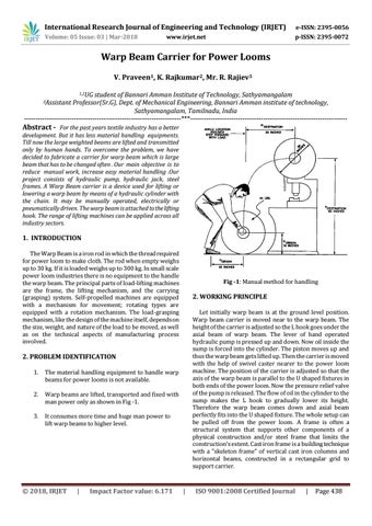
Fig -1: Manual method for handling
2. WORKING PRINCIPLE Let initially warp beam is at the ground level position. Warp beam carrier is moved near to the warp beam. The height of the carrier is adjusted so the L hook goes under the axial beam of warp beam. The lever of hand operated hydraulic pump is pressed up and down. Now oil inside the sump is forced into the cylinder. The piston moves up and thus the warp beam gets lifted up. Then the carrier is moved with the help of swivel caster nearer to the power loom machine. The position of the carrier is adjusted so that the axis of the warp beam is parallel to the U shaped fixtures in both ends of the power loom. Now the pressure relief valve of the pump is released. The flow of oil in the cylinder to the sump makes the L hook to gradually lower its height. Therefore the warp beam comes down and axial beam perfectly fits into the U shaped fixture. The whole setup can be pulled off from the power loom. A frame is often a structural system that supports other components of a physical construction and/or steel frame that limits the construction's extent. Cast iron frame is a building technique with a "skeleton frame" of vertical cast iron columns and horizontal beams, constructed in a rectangular grid to support carrier.
2. PROBLEM IDENTIFICATION 1.
The material handling equipment to handle warp beams for power looms is not available.
2.
Warp beams are lifted, transported and fixed with man power only as shown in Fig -1.
3.
It consumes more time and huge man power to lift warp beams to higher level.
Š 2018, IRJET
|
Impact Factor value: 6.171
|
ISO 9001:2008 Certified Journal
|
Page 438